
Modern Rodding Tech
1957 Ford Ranchero Build Illustration
1. In the initial illustration by Jimmy Smith Concepts, we see the callout for scratch-built bumpers and filler pans at both the front and rear, along with the immediate stance enhancement.
1957 Ford Ranchero
Part 2: How To Rework Bumpers & Filler Panels Using Flat Sheet Metal
BY BRIAN BRENNAN PHOTOGRAPHY BY NOTSTOCK PHOTOGRAPHY & TIN MAN’S GARAGE ARTWORK JIMMY SMITH CONCEPTS
W

e kicked off our build series on the 1957 Ford Ranchero coming out of Tin Man’s Garage (Brian Limberg) in Part 1. Limberg enlisted Jimmy Smith of Jimmy Smith Concepts to illustrate what this highly modified 1957 Ford Ranchero would look like. Since owner Mike Long was on board with these upgrades, “Cool Ranch” started its journey to a rod run near you. From here, we can now see the 1957 Ranchero in metal finish through the lens of John Jackson of NotStock Photography. In Part 2, we will look at a popular modification to all sorts of hot rods—bumper tuck.

To recap in Part 1, we examined the interior and discussed several modifications that, through Jimmy’s artistic eye, provided a starting point for the talented team at Tin Man’s Garage, resulting in something spectacular. Now, in Part 2, we spoke with Limberg and he filled us in on what was happening.

In talking with Limberg, he has long believed that one of Ford’s most noticeable design flaws on the 1957 Ford passenger cars are the front bumpers. Limberg pointed out, “Specifically, the height they were mounted in relation to the ground when compared to the rockers. The amount of framehorn and lower radiator support visible is kind of peculiar; even after radically lowering these cars, it is still an eyesore.”

Beginning at the front—where else? The team at TMG Vision aimed to enhance, but not significantly change, the Ford Ranchero’s appeal. According to Limberg, TMG started by “wedge-sectioning the body” and simultaneously replaced any rusted sheet metal along the rocker panel area. By doing so, TMG was also able to lower the grille and the rest of the front end sheet metal by 1-1/2 inches relative to the ground.

From this point, TMG designed a bumper filler panel that allowed the bumper to lower by an additional inch. Moving to the rear, TMG then replicated the rear bumper profile, which was an inch taller than the original front bumper. From there, the rear bumper was flipped, revealing a new bumper profile that’s “upside down.”

In the end, the side profile of the 1957 Ford Ranchero looked entirely different. Now, the bottom of the front bumper is 3-1/2 inches closer to the ground after these three modifications were completed.

Let’s follow the efforts of Chris Tapp from TMG as he designs the new front bumper and filler pan for Cool Ranch.

1957 Ford Ranchero Build Illustration
2. In Part 2 of our 1957 Ford Ranchero Project (Cool Ranch) at Tin Man’s Garage (TMG), we see just what an improvement to overall appearance and stance the tucked front bumper makes.
Bare metal Ranchero front view at night
3. The craftsmanship from the efforts of TMG is immediately visible. In time, Modern Rodding will carry the final feature.
Bare metal Ranchero rear view at night
4. The rear bumper looks “so right” that you fail to initially realize that we are now looking at a scratch-built rear bumper.
Profile gauge creating a template
5. The profile was taken from the rear bumper and used to create a set of forming dies.
Pullmax machine stamping a clean profile
6. The Pullmax dies were cut from steel and bolted into a universal die holder. The rough shape was initially formed, then passed through the dies to stamp the clean profile.
Brake tool forming recessed panel edges
7. A set of 5/16 radius fingers was used in the brake to form the left and right sides of the recessed panels. The panels were cut and welded along the center peak.
Shrinking radius corners with a torch
8. The recessed pan was flipped over onto the bench with a T-dolly clamped under the edge. An oxy-acetylene torch was used to shrink the corners of the formed radius.
Four stages of sheet metal corner formation
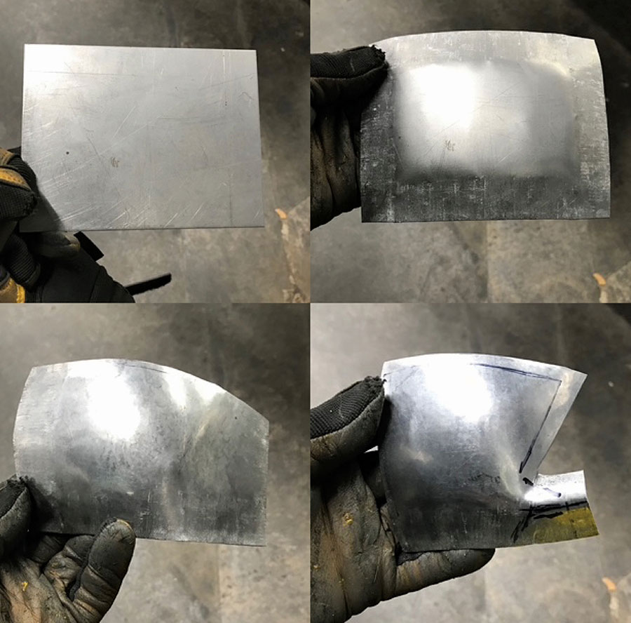
9. A small piece of sheet metal was shrink-formed around the edges. Form was introduced and a planishing hammer was used to stretch the center. It was trimmed, and a T-dolly was utilized to shape the inside corner.
Fabricated metal piece fitted to original bumper
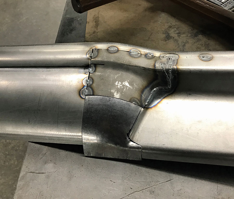
10. The only remaining piece of the original bumper was welded above the piece made in the previous step. The fabricated piece was then final-trimmed and fitted before being welded in place.
Two bumper halves after initial welding
11. Both halves were fully TIG welded, sanded, and given a rough metal finish. Extensions were added to the center of each piece after realizing the design could be improved by aligning those recessed areas more closely with the shape of the grilles.
Joined bumper section showing weld seam
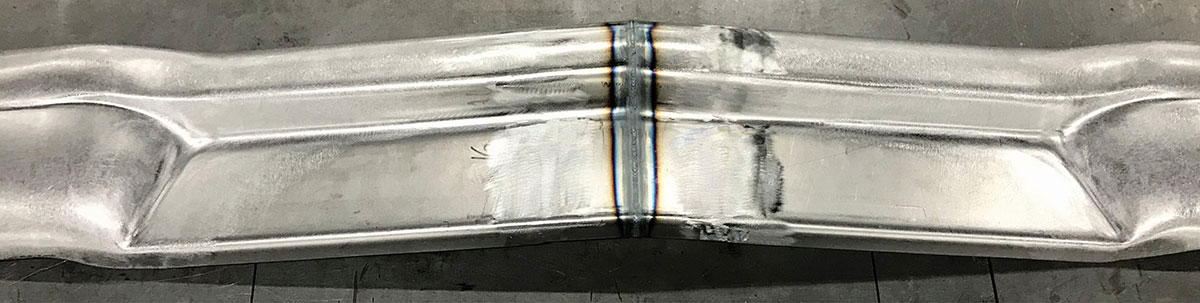
12. The bumper is starting to take shape as both sides are finally welded together, creating one uniform piece.
Forming a flange on the filler panel
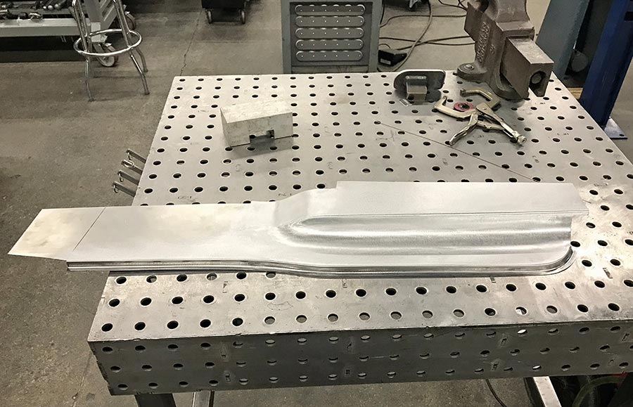
13. The next panel to start working on is the bumper filler panel. A 1-5/16-inch flange was partially formed down to about 30 degrees in the ERCO Former.
Finishing the original panel flange work
14. A die change and table removal were necessary for the ERCO to complete the 3/4-inch flange in the other direction. The panel then flipped back over, and the rest of the original flange was carefully finished with the original set of dies.
Front mockup of bumper and filler panels
15. The trailing edge of the panel was flanged up with a large 1-1/2-inch radius using the ERCO again. A smaller panel was formed and tack welded to the filler panel.
Hand finishing a tapered transition area
16. A closeup shot after the two panels were finally welded in the previous step. The tapered transition area was finished by hand using various hammers, T-dollies, and a planishing hammer.
Sanded weld seam on a metal panel
17. The weld seam was sanded and metal finished on both the left and right sides before welding them together to create one large filler panel.
Fitting panels to flow into wheel opening
18. The focus for these roughly made panels was to ensure the formed edge flows properly into the wheel opening and to create a mounting flange for the fender.
Shrinking a corner with a kick shrinker
19. The corner was shrunk with a kick shrinker while using a T-dolly and a hammer to form the transition radius. The lower edge was trimmed back to remove excess material.
Marking and trimming the side panel flange
20. The side panel was marked along the flanged edge, and the flange material was added and trimmed. The short edge was flanged using pliers and hand tools.
Shaping a metal flange to ninety degrees
21. The edges around the outside were trimmed. The ERCO flanger was used to shape the flange to 90 degrees, and then a T-dolly was employed to continue forming the sheet metal into a slight U-shape.
Side panel installed and welded to body
22. Once the forming and fitting were completed, the panel was installed and finally welded.
Bumper mockup and cardboard pattern work
23. The bumper was mocked up on the bench, and a wire form was made to mimic the corner so a cardboard pattern could be created.
Cardboard patterns transferred to sheet metal blanks
24. The patterns were transferred to sheet metal blanks and cut out on a band saw. The shrinking procedure is marked on the blanks to ensure consistency for both sides during the process.
Rough shaping of the bumper ends
25. A combination of shrinking and T-dolly work was used to shape the bumper ends roughly. Next, they will be smoothed with a planishing hammer and hand tools.
Test fitting the bumper top edge alignment
26. A test-fit on the right side was performed to see how the top edge was shaping up and to identify where additional work is needed to make the end fit properly.
Creating taper detail in a machine
27. The taper detail is made by running the panel the full length and then removing it. Next, slightly increase the die engagement depth and run it again, this time with slightly less length than the previous pass.
Before and after offset step bead detail
28. This previous process is repeated multiple times to achieve the desired taper length. Comparison of bumper ends showing the before and after offset step bead detail.
Forming metal edges to cap bumper ends
29. Some material was cut from the corners, then the edge was formed with a T-dolly to cap the bumper ends.
Heating seams with a torch for shrinking
30. The seams were heated with a torch to help allow the material to shrink as needed in the tight corners. The corners were fully dressed after welding.
Bumper ends welded to the center section
31. Once the bumper ends were fully metal finished, they were fitted and fully welded to the center bumper section.
Final metal finishing using hammers and dollies
32. The bumper ends were metal finished with hammers and dollies, along with picking and light filing. Block sanding with 80-grit is preferred to minimize material removal.
Finished bumper angle below the headlight
33. Notice the smooth angle of the finished bumper that complements the headlight eyebrows and grille angle.
Front view of the completed tucked bumper
34. Completed view of the new bumper being lower to the ground, which now covers up more of the framehorns and radiator crossmember than the factory version.
In The Garage Media
TIN MAN’S GARAGE

Modern Rodding
VOLUME 7 • ISSUE 70 • 2026