Modern Rodding TECH

InTheGarageMedia.com

mechanic torques an ARP fastener on the LS block
LS Bare Block Performance Package typography

Part 1: Prepping, Inspecting, and Assembling the Bottom End of Our Summit Racing LS

By RYAN Manson Photography by Brian Brennan Videography by Ryan Foss
W

hen it comes to building a performance LS engine package, there’s no better source for not only those internal components but also the tools required to properly measure and inspect those components than Summit Racing. Not only does Summit stock all the usual suspects when it comes to engine parts and speed equipment, their private label line offers a laundry list of products with an eye toward quality and affordability. From the pan to the valve covers, we turned to Summit at every corner of our latest LS build, and they had everything we needed.

Speaking of performance LS and LT engine packages, the guys at American Heritage Performance (AHP) have successfully carved out a niche in a market flooded with performance engine builders and aftermarket manufacturers. From their Archangel LS7 cylinder heads that powered the world’s fastest naturally aspirated C6 Z06 Corvette (8.895 seconds at 154 mph in the quarter-mile!) to their 700-rwhp 442ci stroker LS7 crate engine package; to say the AHP crew know how to make power using the latest GM small-block would be to put it lightly. That said, it should come as no surprise that when it came time to assemble a powerplant based on a 5.3L iron block, the AHP crew were confident they could assemble a reliable engine that would make impressive power to boot.

Keeping a tightly wound engine together requires quality hardware and for that end Automotive Racing Products fasteners will be used from the main studs to the head bolts. A successful combination to be sure, AHP’s Kyle Martelli will be bringing in his expertise to carefully inspect and assemble every aspect of the LS build.

To begin our build, an iron block LS engine was located, purchased, and disassembled before being delivered to AHP. Once there, it was carefully measured and inspected before being deemed acceptable and sent off for machining. Decked, bored, honed, and brought within closer specs than GM could ever imagine, the bare block was then rolled into AHP’s clean room where the build process could begin.

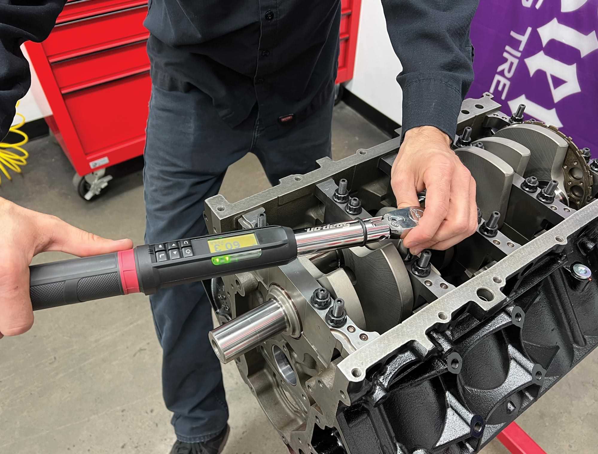
Martelli will be inspecting the block first, checking crankshaft main bearing clearances before installing the cam bearings. From there, the crankshaft will be ready for installation and a few additional procedures will follow before the bottom end of our Summit Racing LS build is complete. We’ll come back next time and cover the rotating assembly, heads, and valvetrain before putting our mighty LS engine on AHP’s dyno where it will be broken in and its abilities demonstrated.

a 5.3L iron-block sits on an engine stand in a garage
1. The foundation for our Summit Racing LS engine build is this 5.3L iron-block sourced locally and prepped by the guys at American Heritage Performance (AHP). Following the machine work, engine builder Kyle Martelli chased all the threaded passages in the block before giving it a thorough cleaning. A couple coats of gloss black engine enamel was the final step in prepping the block for our build.
top view of an organized array of ARP hardware, including head bolts (PN 134-3609) and main stud nuts and washers
2. A clean workspace is paramount to a successful engine build, something Martelli and the AHP crew practice diligently. Here, Martelli has organized an array of ARP hardware, including head bolts (PN 134-3609) and main stud nuts and washers.
close view of the ARP main studs (PN 234-5608), already installed to the block
3. ARP main studs (PN 234-5608) have already been installed in the block in anticipation of the first step of the build. A dab of ARP assembly lube is used before the studs are installed finger tight.
a Summit Racing Pro LS crank (PN SUM-180LS362224x) featuring a 3.622-inch stroke and 4340 forged steel construction sits atop a work surface
4. The crankshaft for our build is a Summit Racing Pro LS crank (PN SUM-180LS362224x) that features a 3.622-inch stroke and 4340 forged steel construction. Before the crankshaft is installed, Martelli will check the clearances between the installed main bearings and the crank’s journals to ensure the tolerances are within spec.
close view of an installed Clevite main bearing
5. The first step in this process is to install the Clevite main bearings from Summit Racing (PN MS-2199H).
mechanic torques a main cap and bearing
6. Next, the main caps and their corresponding bearings are installed and torqued to spec.
mechanic uses a Summit dial bore gauge (PN SUM-900041) to measure the ID of each main cap
7. A dial bore gauge is then used to measure the ID of each main cap. Summit (PN SUM-900041) is a great tool for this procedure.
mechanic measures the crankshaft’s main bearing
8. Next, Martelli measures the crankshaft’s main bearing journals and compares the two results. This is known as the crankshaft main bearing clearance. Our results vary between 0.0026-0.0027 inch, well within Clevite’s specs.
mechanic uses a Summit Pro LS Main Cap Puller (PN SUM-900339) to remove the LS main caps
9. Removing LS main caps when using studs can be challenging, but this Summit Pro LS Main Cap Puller (PN SUM-900339) makes the process painless and prevents damage to the cap or bearing.
parts from a Summit plug kit (PN SUM-G1584) sit on a surface
10. There are a handful of galleries that need to be plugged, for which we’ll be using a Summit plug kit (PN SUM-G1584).
view of the driver side of the LS block showing two oil galleries and a coolant passage
11. On the driver side, there are two oil galleries and a coolant passage that needs to be blocked off.
close view of a coolant drain hole toward the rear of the block
12. Over on the passenger side toward the rear of the block, this plug is in a great location to drain the engine’s coolant when the time arises.
mechanic installs the "barbell" to the block
13. The “barbell” is installed at the back of the block and serves an important job regarding proper filtration of the engine oil.
the “barbell” sits flush with the engine block
14. Properly installed, the “barbell” sits flush with the engine block and will be held in place by the rear main cover.
the freeze plug, installed in the front oil gallery hole
15. A traditional, pressed freeze plug is installed in the front oil gallery hole. Forgetting this plug will result in unfavorable oil pressure. Those orange paint markings are a neat touch that will be seen throughout our engine build. Martelli uses this technique as a method for quick visual inspection to ensure that a fastener has been properly installed and torqued to spec.
two Dura-Bond cam bearing sets (PN DUR-CH-10) sit on a work surface
16. While the block is still bare, Martelli takes advantage of the opportunity to install the camshaft bearings. A Dura-Bond cam bearing set (PN DUR-CH-10) will be used, seen here with a light coat of engine oil applied to ease installation.
starting at the rear of the block the mechanic uses a Summit Cam Bearing Installation Tool (PN SUM-900131) to carefully drive each bearing into place
17. The cam bearings vary in size and need to be installed in a specific order. Starting at the rear of the block, Martelli uses a Summit Cam Bearing Installation Tool (PN SUM-900131) to carefully drive each bearing into place.
close view of a purposefully improperly installed cam bearing
18. Proper bearing placement in the journal is of utmost importance. Here, a cam bearing has been installed improperly on purpose to illustrate the importance of lining up the oil gallery holes in the bearing with the same gallery holes in the journal, as well as its proper spacing, fore and aft, in the journal itself.
mechanic attempts to install a core camshaft to the block
19. A core camshaft is used to ensure that the cam bearings have been properly installed and are aligned. We’ll be installing the actual camshaft later in the build.
mechanic applies a thin layer of engine oil to the crankshaft’s main journals
20. With the cam bearings in place, we can begin the installation of the rotating assembly, starting with the crank. Martelli applies a thin layer of engine oil to both the crankshaft’s main journals …
mechanic applies a thin layer of engine oil to the engine’s main bearings
21. … as well as the engine’s main bearings …
Mechanic carefully sets the crank in place
22. … before carefully setting the crank in place.
additional oil is applied to the lower main bearings before each cap is installed
23. Next, additional oil is applied to the lower main bearings before each cap is installed.
mechanic installs a main bearing cap
24. Our LS engine utilizes five main bearings to support the crank, with the center bearing acting as the thrust bearing, controlling the crankshaft’s longitudinal movement.
an installed main bearing cap with a position number and arrow markings on its top surface
25. The main caps are position and rotational specific. Note the position number and arrow markings on this rear main cap to prevent incorrect installation. The 24x crankshaft reluctor wheel transmits piston and crankshaft position to the ECU via the crankshaft position sensor and is also visible in this image.
ARP assembly lube is applied to the threads of each main stud
close view of a main stud covered with ARP assembly lube
26-27. ARP assembly lube is applied to the threads of each main stud as well as under the nut or washer to prevent galling and to lubricate the fastener to ensure proper torque readings.
mechanic torques the ARP fasteners in a progressive manner toward the final torque rating of 60 lb-ft.
28. Martelli starts at the center and works his way toward the outer main caps, torquing the ARP fasteners in a progressive manner toward the final torque rating of 60 lb-ft. The center cap is left loose until after the thrust is set by driving the crankshaft into the block, aligning the upper and lower thrust bearings. Once aligned, the center cap fasteners are torqued to 60 lb-ft as well.
mechanic torques smaller side bolt to 20 lb-ft
29. All LS engines feature a six-bolt main cap design featuring four 10mm center fasteners and two 8mm cross bolts. These smaller side bolts are torqued to 20 lb-ft with a layer of RTV on the shoulder of each to prevent oil from leaking.
mechanic repeats his “torque-striping” technique
30. With the main cap fasteners torqued to spec, Martelli repeats his “torque-striping” technique.
the LS block goes through its final installation steps with the use of a dial indicator
31. The last procedure of the crankshaft installation is twofold, both of which use the installation of a dial indicator at the back of the block, indicating off the crankshaft reluctor wheel. First, the crankshaft endplay is measured by carefully moving the crankshaft fore and aft and noting the measured movement. Our crankshaft endplay came out at 0.006 inch, well within OE spec. The second procedure is to check the crankshaft reluctor wheel’s runout. GM spec calls for a maximum of 0.040-inch runout, though that’s rather high. Our wheel came in around 0.009 inch, which is much better.
American Heritage Performance
(310) 326-2399
americanheritageperformance.com
Automotive Racing Products (ARP)
(800) 826-3045
arp-bolts.com
Summit Racing
(800) 230-3030
summitracing.com
Modern Rodding

VOLUME 3 • ISSUE 24 • 2022