Modern Rodding Tech
InTheGarageMedia.com
1. Our 348 Chevy is equipped with a PerTronix Flame-Thrower ignition system. Now other vintage engines can take advantage of the same technology. We also added PerTronix 8.0 mm Mag x 2 spark plug wires with those cool ceramic ends to our W-motor. (Editor’s Note: We checked, and Ron was trying to sneak the vintage W-motor through his kitchen door! —B.B.)
Hot Spark for Cool Engines
PerTronix Flame-Thrower Distributors for Vintage V-8s
By Ron Ceridono Photography by The Author
W

hile there is much to be said in favor of contemporary engines with the latest in computer-controlled everything, it’s hard to beat the charm of an early engine. Nostalgia may be the motivation to run such a powerplant; it may be the desire for simplicity or just the urge to tap into the roots of the hobby. But whatever the reason, hot rods with vintage engines are cool, but that doesn’t mean they can’t benefit from technology.

One of the shortcomings of many early engines is the ignition system. Points and condensers were fine in their day, but electronic ignitions would prove to be vastly superior; some of that proof came from an unlikely source. In the early ’70s an engineer at Per-Lux, a company that made lighting products for the trucking industry (such as those round stainless steel lights with the horizontal baffles), developed an electronic ignition module to replace points and condensers. The intended application was forklifts and other industrial engines, but it didn’t take long for the Ignitor to become a popular automotive update as well. It became known that the Ignitor provided a much more accurate trigger signal to the coil, which improved timing accuracy and ignition misfires at high rpm due to the point bounce was eliminated. The Ignitor conversions put an end to dealing with points. Something anyone who had adjusting points with a match book cover on the side of the road in the dark could appreciate.
PerTronix Ignition Modules
In 1991 the Per-Lux ignition division changed hands and PerTronix came to be. Ignition systems were the focus and things got serious. Today PerTronix offers a wide variety of ignition products, including three versions of electronic ignition modules. The original Ignitor is still popular for converting original distributors to electronic operation. Since they are almost undetectable many “restored” award winners have one under the distributor cap for the increased reliability and spark voltage they offer. The Ignitor II includes a few more features than the original Ignitor, such as a micro-controller that adjusts dwell throughout the engine’s rpm range. The result is up to four times more voltage at the plugs. For serious performance applications PerTronix offers the Ignitor III. It can produce up to five times more spark energy than a points system and includes a digital rev limiter with LED feedback and Multi Spark all the way to redline.
PerTronix Coils
Ignition coils are step-up transformers that dramatically increase battery voltage to fire the spark plugs (if you’ve ever been zapped by a plug wire the increase is obvious). Inside the coil are two coils of wires, or windings. The primary winding in the center of the coil has relatively few windings, while the secondary winding that wraps around it has many more. When the points are closed, or the electronic control allows current to flow through the primary windings, a magnetic field is created. When the points open (or the electronic device that controls current flow shuts off), the magnetic field collapses and makes current flow in the secondary windings. While it stands to reason more current in the primary would make more voltage in the secondary, the current flow is limited by the ability of the points, or the electronics in place, to handle it.

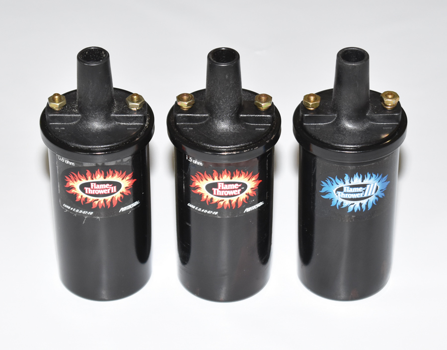
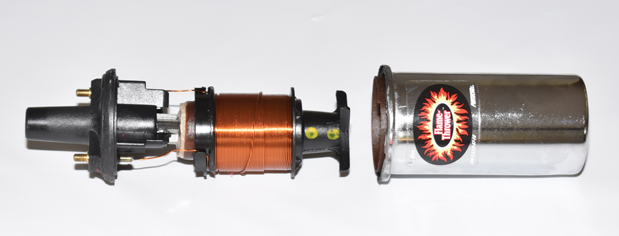
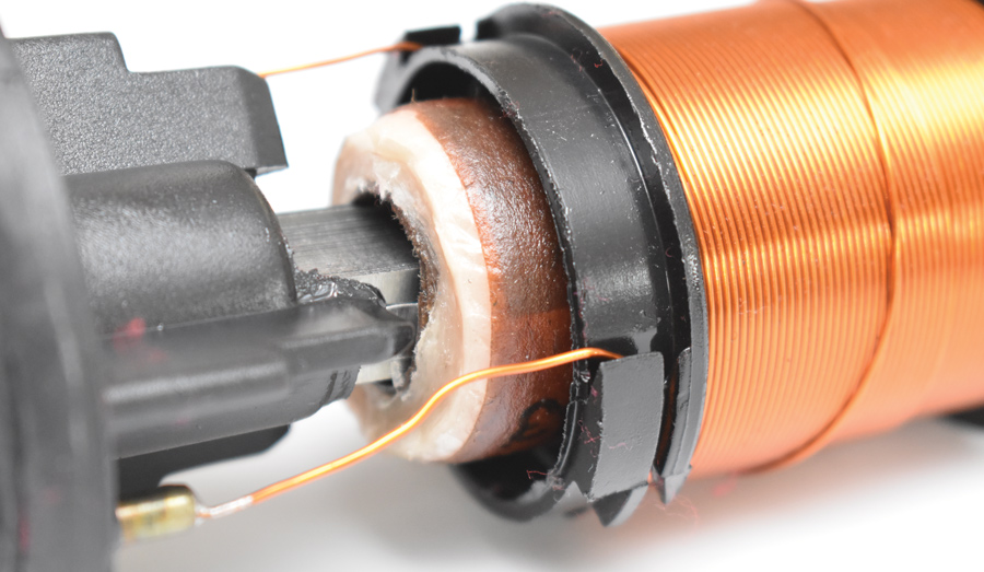
PerTronix offers three distinctly different oil-filled, canister-style coils. While they look virtually the same, Don Lindfors of PerTronix explains that they are identified by the ignition system they are designed for:

“The Flame-Thrower 40,000V coils have internal resistance rated at 1.5 or 3.0 ohms. The 3.0-ohm coil should be used on PerTronix Ignitors installed on four- and six-cylinder engines while 1.5-ohm coils should be used for eight-cylinder applications. These coils can be used on virtually any inductive (non-capacitive discharge) ignition system, including points systems.

“Flame-Thrower II coils have lower resistance, 0.6 ohms for use with Ignitor II ignition systems as well as many other high-energy ignitions. The low resistance helps to produce up to 45,000 V. This higher voltage allows larger spark plug gaps for added power and better fuel economy.

“Flame-Thrower III coils were developed for use with the new Ignitor III electronics. The extremely low resistance of 0.32 ohms results in 45,000 V and a coil that charges to peak current typically 30-70 percent faster than the other coils. It should be noted that these coils are compatible with Ignitor III electronics only.”

Flame-Thrower Distributors
Although the Ignitor was, and remains, an excellent method to convert a point and condenser-equipped distributor to electronic operation, PerTronix Flame-Thrower Billet Distributors offer tuning advantages not often possible with vintage OEM distributors, they are also the perfect replacement for old worn-out OEM distributors. Due to today’s fuels distributor advance curves are much different than they once were. PerTronix distributors come with a variety of advance springs and limiters to customize the advance curve for optimum performance.

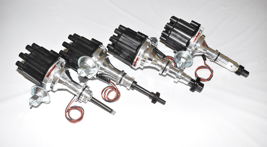
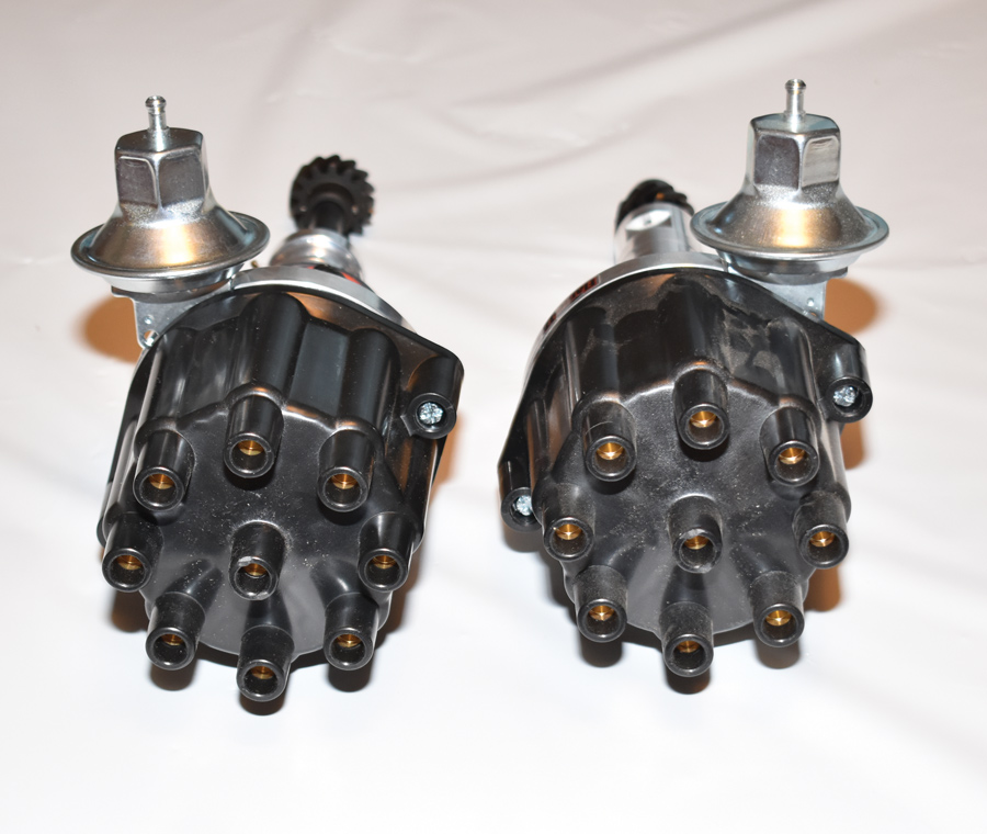
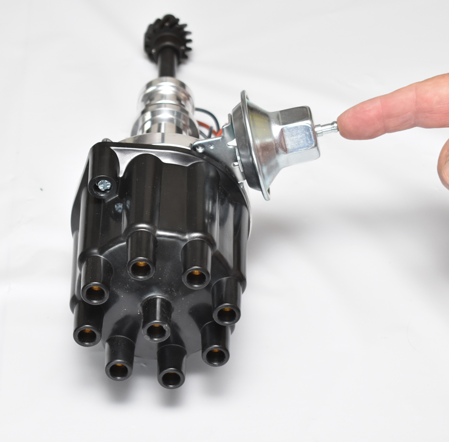
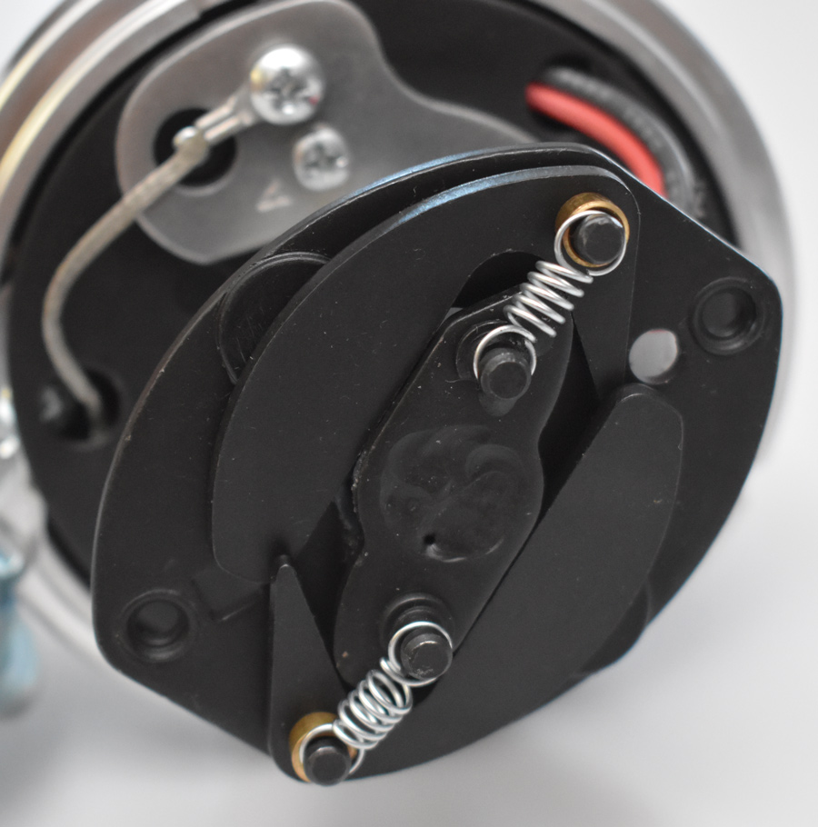
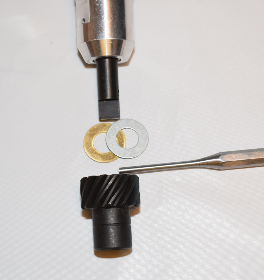
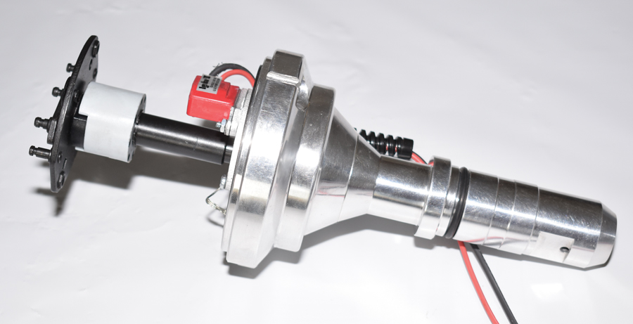
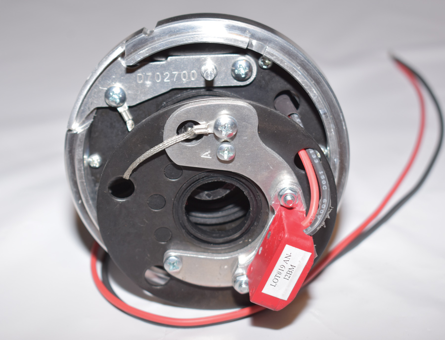
Recently PerTronix expanded their line of vintage engine Flame-Thrower distributors to include Ford Y-blocks, early Chrysler Hemis, Buick Nailheads, early Cadillacs, Studebaker V-8s, and even Corvairs. All these distributors feature PerTronix II electronics, CNC-machined 6061-T6 billet aluminum housings, and precision-machined steel shafts with upper ball bearings and lower bushings. All are equipped with coated drive gears that are compatible with OEM and retrofit roller lifter camshafts.

Installing a Flame-Thrower distributor is plug-and-play—drop the distributor in place, connect the black wire to the negative (-) side of the coil and the red wire to the positive (+) side and that’s it. As the Ignitor and the Flame-Thrower Coil are designed to run with a full 12 V, remove the ballast resistor (or bypass the resistor wire if there is one) from the ignition wiring and you’re ready to be pointless—but pointless in a good way.

Here are four of the new additions to the Flame-Thrower vintage distributor line. Left to right: 331-354 Chrysler; Ford Y-block; Cadillac 331, 365, 368, 390 (’54-’63); and Buick V-8 Nailhead 264,332, 364, 401, and 425.
2. Here are four of the new additions to the Flame-Thrower vintage distributor line. Left to right: 331-354 Chrysler; Ford Y-block; Cadillac 331, 365, 368, 390 (’54-’63); and Buick V-8 Nailhead 264,332, 364, 401, and 425.
The location of the vacuum advance canister will vary depending on the direction the rotor turns. On the left is a distributor that rotates counterclockwise (CCW), the distributor on the right rotates clockwise (CW).
3. The location of the vacuum advance canister will vary depending on the direction the rotor turns. On the left is a distributor that rotates counterclockwise (CCW), the distributor on the right rotates clockwise (CW).
A trick almost as old as Brian Brennan to determine which way the rotor spins is to point at the vacuum advance, which will indicate the direction of rotation —this one rotates CCW.
4. A trick almost as old as Brian Brennan to determine which way the rotor spins is to point at the vacuum advance, which will indicate the direction of rotation —this one rotates CCW.
Below the rotor are the centrifugal advance weights and springs. From the factory, mechanical advance is limited to 24 degrees. The springs determine when the advance starts and the rate of advance. The silver springs start with 3 degrees of advance at 1,500 rpm with 24 degrees at 3,500 rpm.
5. Below the rotor are the centrifugal advance weights and springs. From the factory, mechanical advance is limited to 24 degrees. The springs determine when the advance starts and the rate of advance. The silver springs start with 3 degrees of advance at 1,500 rpm with 24 degrees at 3,500 rpm.
Two additional sets of springs are included with each distributor. The copper-colored springs provide the fastest advance curve with 5 degrees at 1,000 rpm and 24 degrees at 2,000 rpm. The black springs proved the slowest curve with 3 degrees at 2,000 rpm and 24 degrees at 5,000 rpm. It is possible to mix springs to produce custom curves.
6. Two additional sets of springs are included with each distributor. The copper-colored springs provide the fastest advance curve with 5 degrees at 1,000 rpm and 24 degrees at 2,000 rpm. The black springs proved the slowest curve with 3 degrees at 2,000 rpm and 24 degrees at 5,000 rpm. It is possible to mix springs to produce custom curves.
Another tuning option is provided by these limiters. They are used in pairs and are marked 6, 8, and 10. Using a pair of sixes limits total advance to 12 degrees, the 8s limit advance to 16 degrees, and the 10s limit advance to 20 degrees.
7. Another tuning option is provided by these limiters. They are used in pairs and are marked 6, 8, and 10. Using a pair of sixes limits total advance to 12 degrees, the 8s limit advance to 16 degrees, and the 10s limit advance to 20 degrees.
The advance limiters are installed under the advance springs with the ends wrapped around the weights.
8. The advance limiters are installed under the advance springs with the ends wrapped around the weights.
In some performance applications it may be desirable to install either the mechanical or vacuum advance lockouts—both require partially disassembling the distributor. First the drive gear is removed by driving out the roll pin that secures it to the shaft. Note the position of the thrust washers.
9. In some performance applications it may be desirable to install either the mechanical or vacuum advance lockouts—both require partially disassembling the distributor. First the drive gear is removed by driving out the roll pin that secures it to the shaft. Note the position of the thrust washers.
With the gear removed the shaft can be removed from the housing.
10. With the gear removed the shaft can be removed from the housing.
Here the distributor shaft has been pulled up from the advance plate—note the pin (arrow) that fits into the slot advance plate.
11. Here the distributor shaft has been pulled up from the advance plate—note the pin (arrow) that fits into the slot advance plate.
Seen from the bottom, the pin (arrow) attached to the flange on the distributor shaft fits into the slot in the advance plate. It limits the amount of movement, thus the amount of advance that is available.
12. Seen from the bottom, the pin (arrow) attached to the flange on the distributor shaft fits into the slot in the advance plate. It limits the amount of movement, thus the amount of advance that is available.
Here the distributor shaft has been pulled up from the advance plate—note the pin (arrow) that fits into the slot advance plate.
13. With the advance plate removed from the shaft, the slot in the advance plate can be seen.
The plastic mechanical advance lockout that comes with the distributor’s tuning components snaps into the slotted hole in the advance plate.
14. The plastic mechanical advance lockout that comes with the distributor’s tuning components snaps into the slotted hole in the advance plate.
When the advance plate is reinstalled the pin fits into the lockout (arrow) eliminating movement and locking out the advance.
15. When the advance plate is reinstalled the pin fits into the lockout (arrow) eliminating movement and locking out the advance.
In some instances, it may be advantageous to eliminate the vacuum advance. To do that the distributor shaft is removed and the module assembly is removed by taking off the snap rings.
16. In some instances, it may be advantageous to eliminate the vacuum advance. To do that the distributor shaft is removed and the module assembly is removed by taking off the snap rings.
Under the snap ring will be shims. Make sure to reinstall them during reassembly.
17. Under the snap ring will be shims. Make sure to reinstall them during reassembly.
 With the snap rings removed the module assembly can be moved up to gain access to the vacuum advance retaining screws. Don’t disconnect the ground wire from the module mount during this process.
18. With the snap rings removed the module assembly can be moved up to gain access to the vacuum advance retaining screws. Don’t disconnect the ground wire from the module mount during this process.
 In normal operation the vacuum advance moves the module assembly to alter the ignition timing. For hard-core performance and racing applications where fuel economy is not a concern the vacuum advance lockout can be installed.
19. In normal operation the vacuum advance moves the module assembly to alter the ignition timing. For hard-core performance and racing applications where fuel economy is not a concern the vacuum advance lockout can be installed.
The lockout plate is secured to the housing with the original vacuum advance screws. Note the pin (arrow) on the lockout plate.
20. The lockout plate is secured to the housing with the original vacuum advance screws. Note the pin (arrow) on the lockout plate.
When the module is replaced the pin in the lockout plate fits into the hole where the vacuum advance connected. The module assembly will now remain stationary.
21. When the module is replaced the pin in the lockout plate fits into the hole where the vacuum advance connected. The module assembly will now remain stationary.
These oil-filled coils look the same, but their applications are different. On the left is a Flame-Thrower II with 0.6-ohm resistance, center is a Flame-Thrower with 1.5-ohm resistance, and on the right is a Flame-Thrower III with 0.32-ohm resistance. It’s important that each is used in the proper application.
22. These oil-filled coils look the same, but their applications are different. On the left is a Flame-Thrower II with 0.6-ohm resistance, center is a Flame-Thrower with 1.5-ohm resistance, and on the right is a Flame-Thrower III with 0.32-ohm resistance. It’s important that each is used in the proper application.
Here the internals of an ignition coil has been removed from its canister. The canister is normally filled with oil or Epoxy (for high-vibration applications) to act as an insulator and prevent contamination from moisture.
23. Here the internals of an ignition coil has been removed from its canister. The canister is normally filled with oil or Epoxy (for high-vibration applications) to act as an insulator and prevent contamination from moisture.
This closeup shows the coil’s primary windings with a laminated core in the middle to concentrate the magnetic field that is created. On the outside of the primary windings are the many turns of wire that comprise the secondary windings.
24. This closeup shows the coil’s primary windings with a laminated core in the middle to concentrate the magnetic field that is created. On the outside of the primary windings are the many turns of wire that comprise the secondary windings.
PerTronix Performance Brand
(909) 599-5955
pertronixbrands.com
Modern Rodding
VOLUME 2 • ISSUE 13 • 2021