
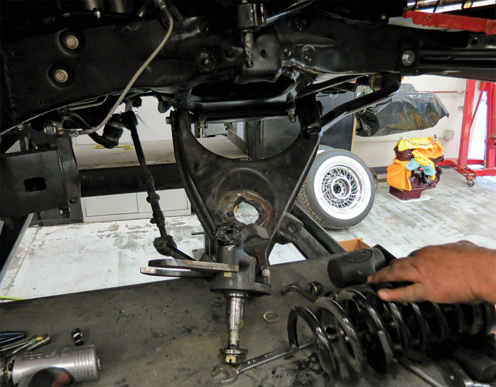
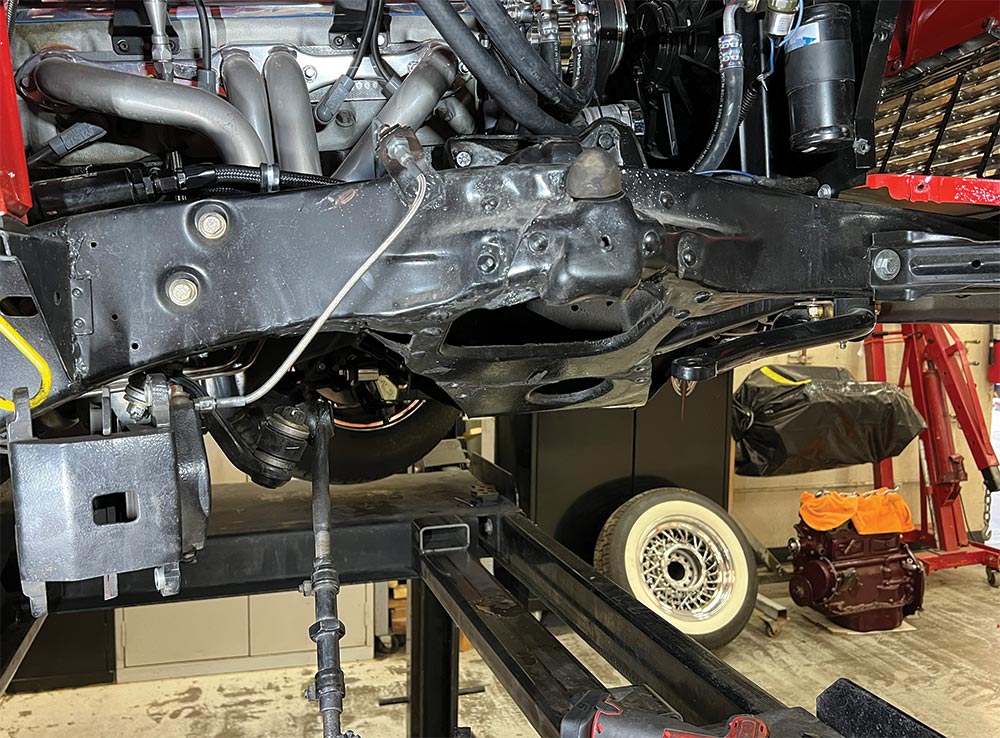
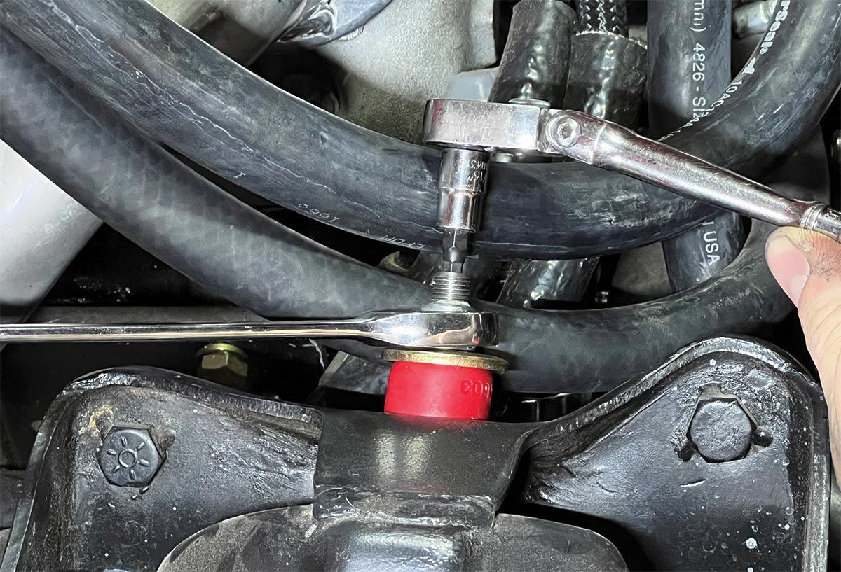
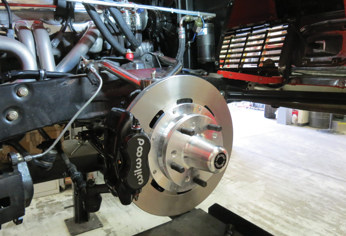
1. Our objective is to remove the factory IFS and replace it with a more modern, better functioning system coupled with the latest in braking capabilities.
 Photography by Brian Brennan
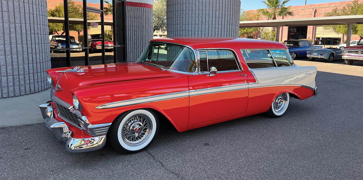
e’re sure you can relate when we say an old car is never truly finished. There is always a way to continue refining and upgrading your project car. Such is the case with this ’56 Chevy Nomad, a mildly modified street cruiser that has plenty of miles under its belt. The car recently rolled into Hot Rods by Dean, and the intention was to upgrade its suspension and braking system. Although plans involve a complete front and rear overhaul, we’re focusing on the front in this installment and will cover the rear suspension upgrades in a future issue.
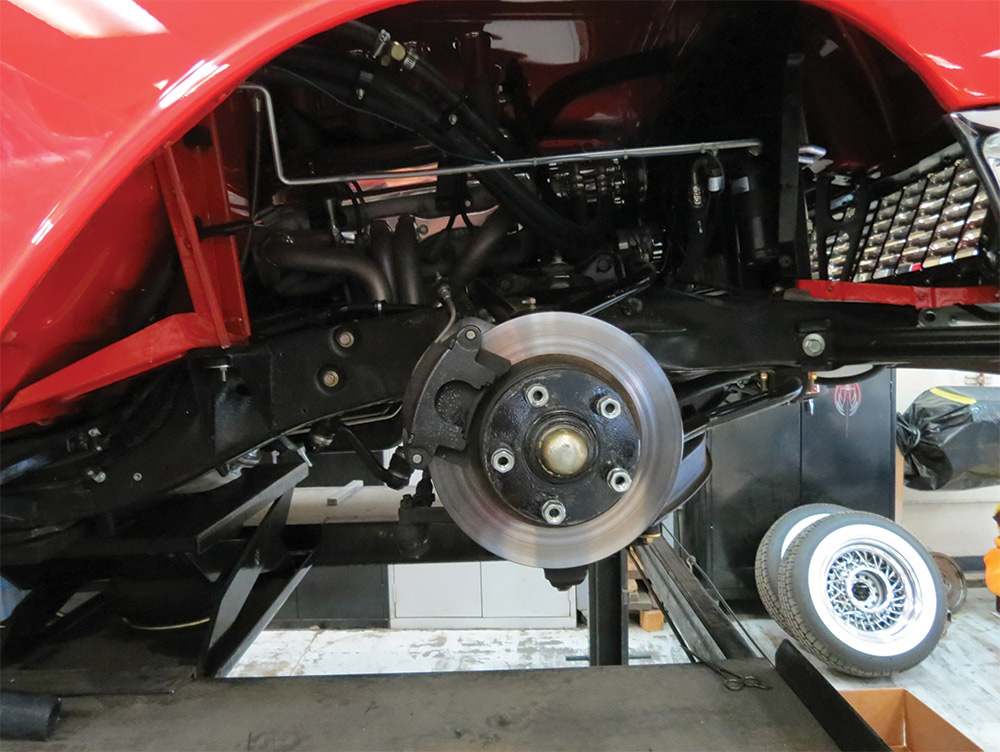
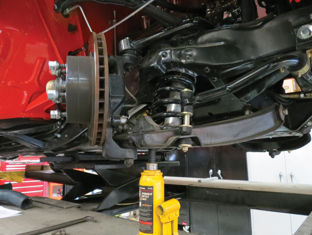
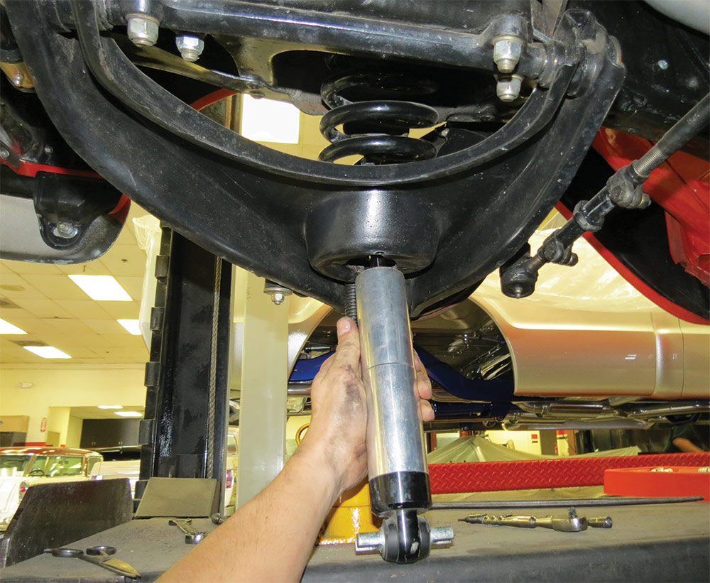
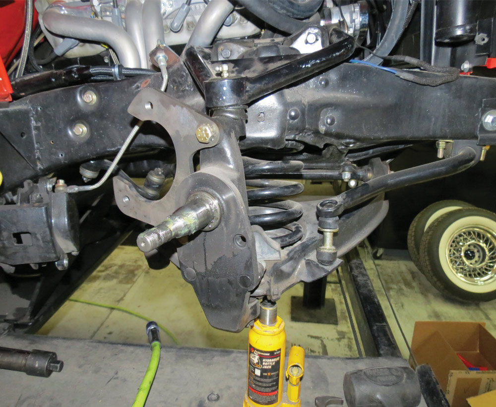
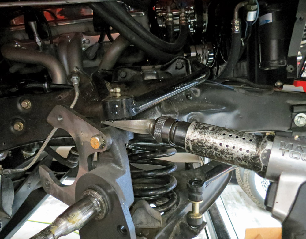
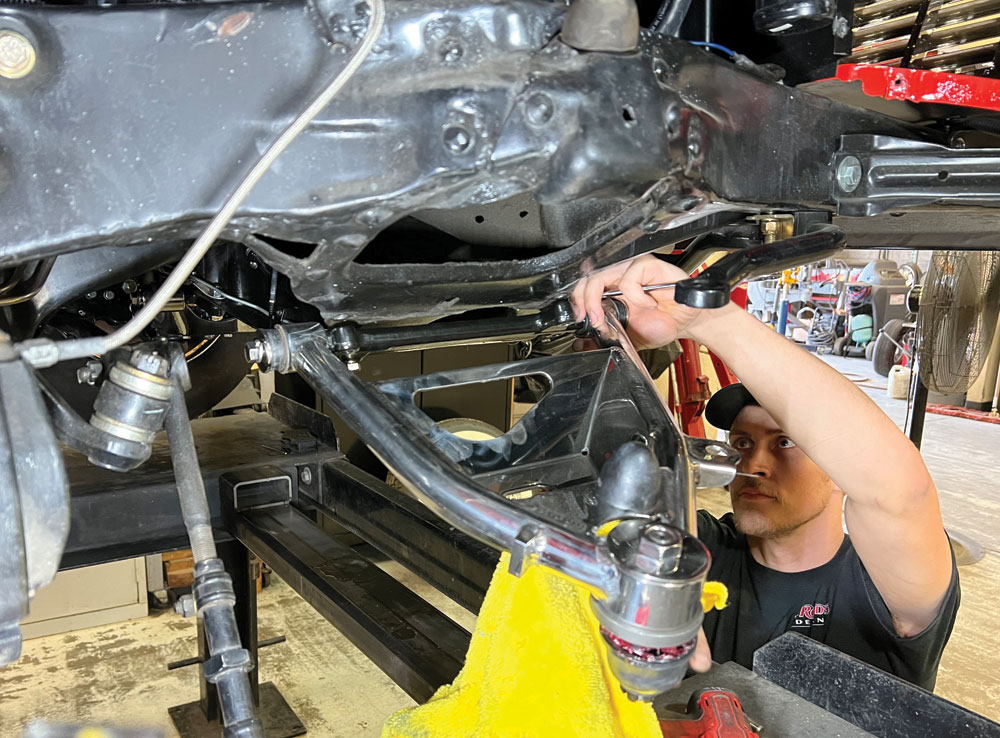
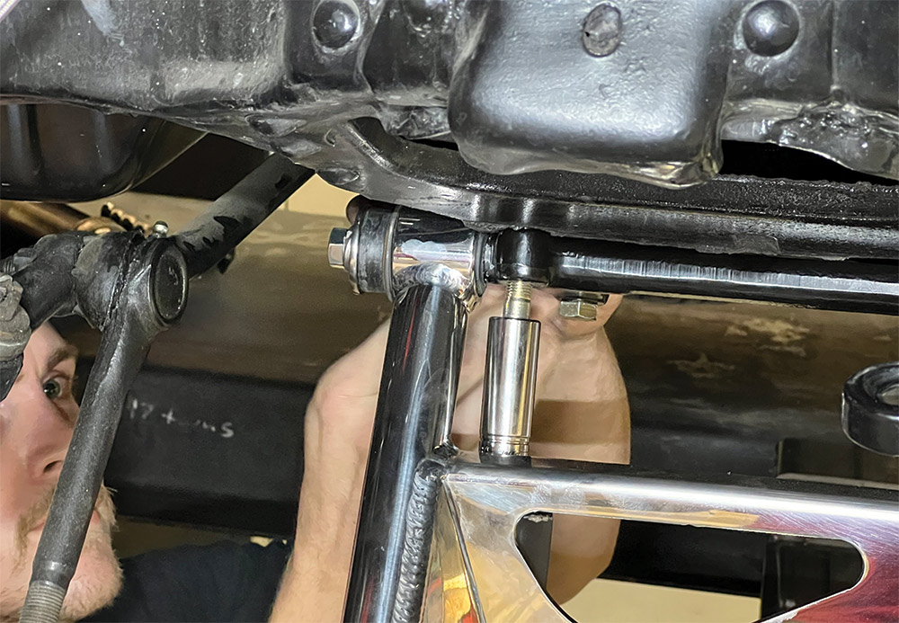
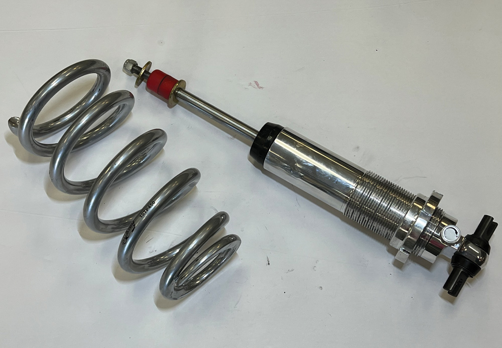
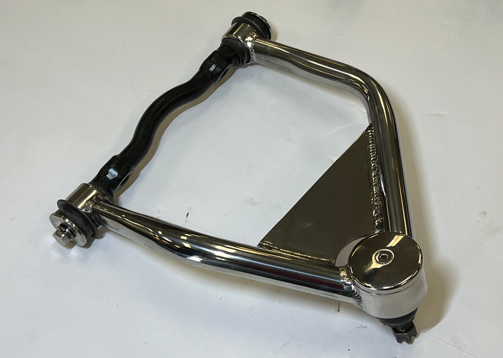
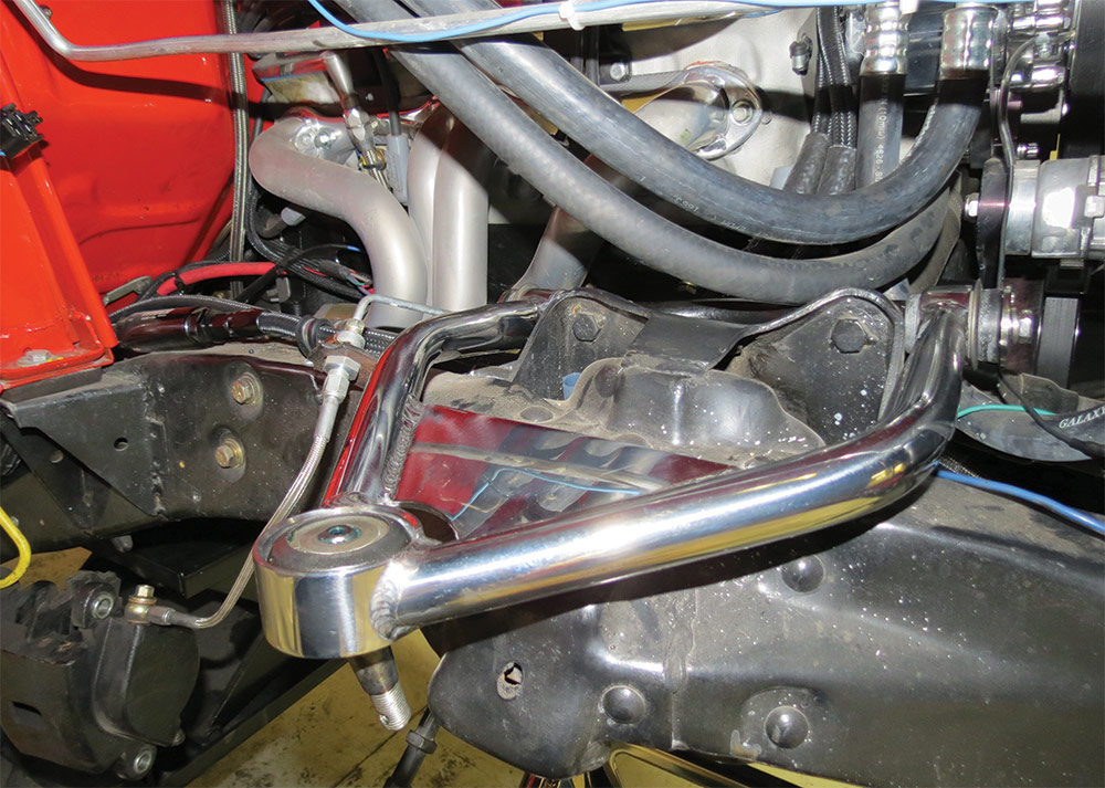
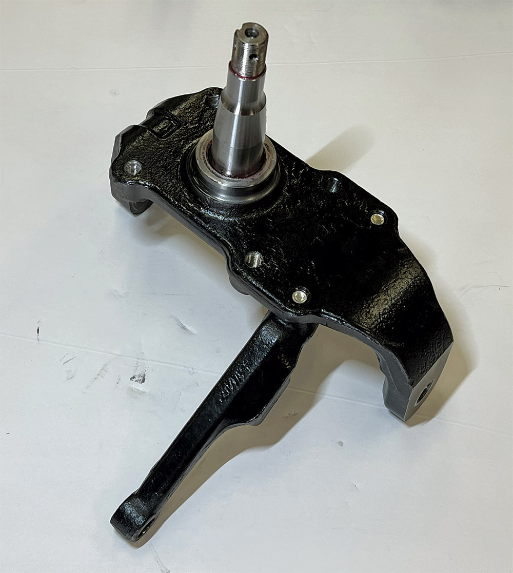
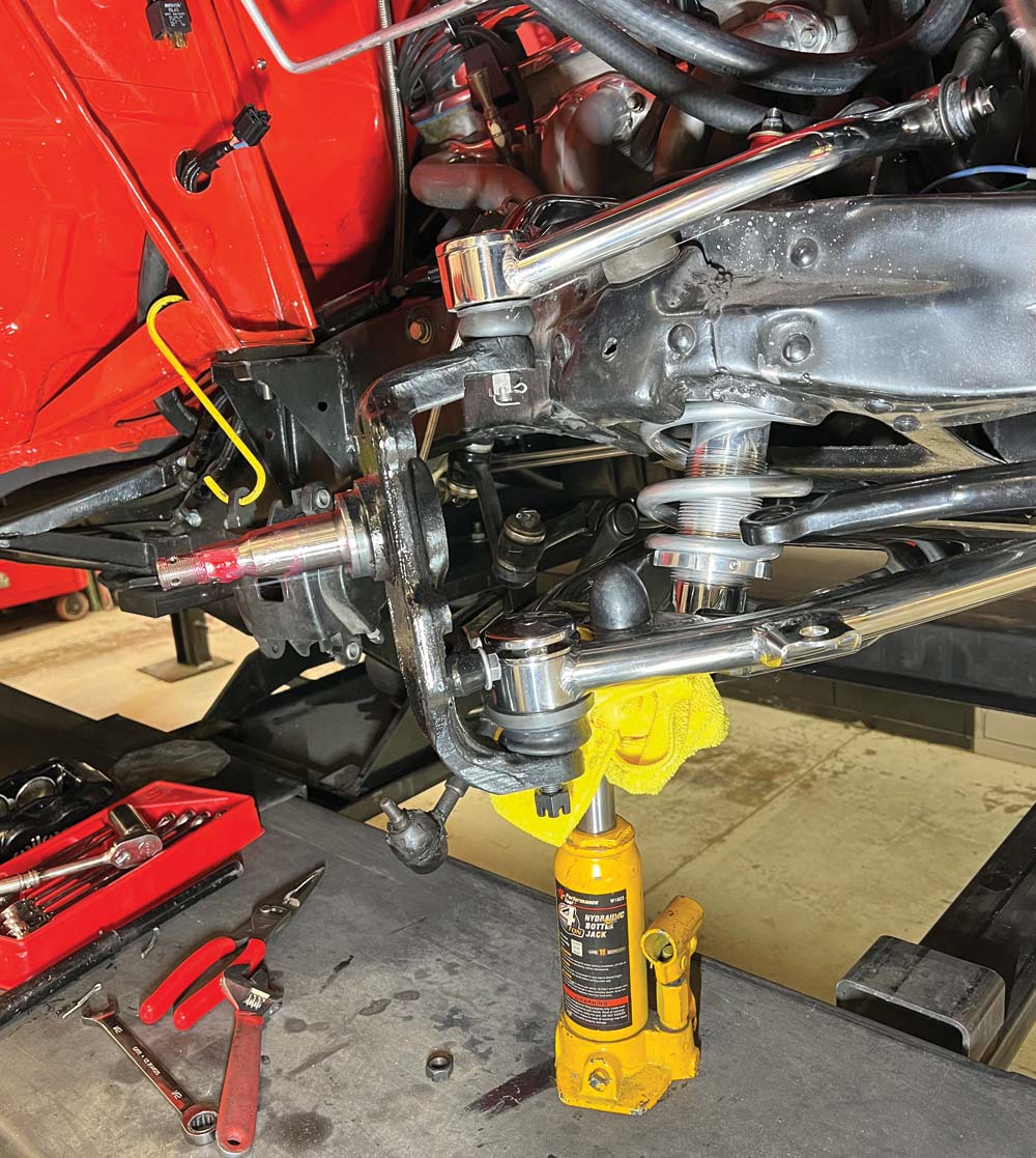
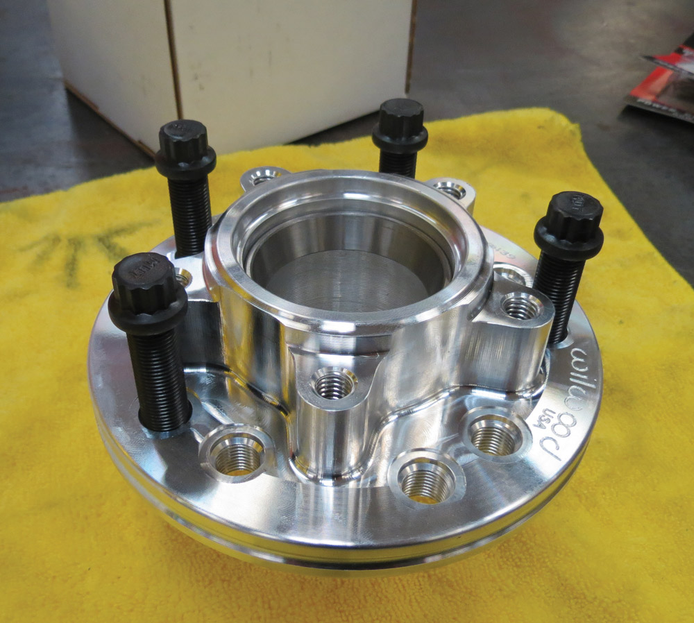
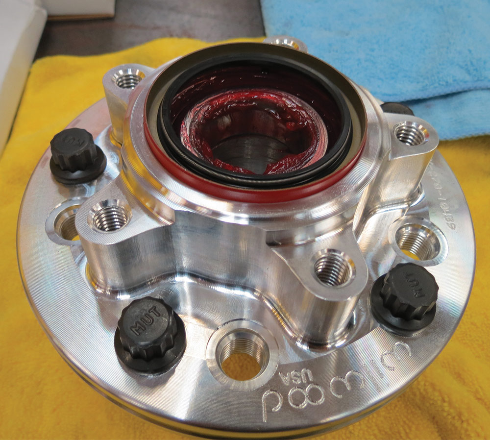
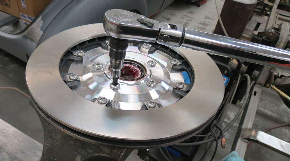
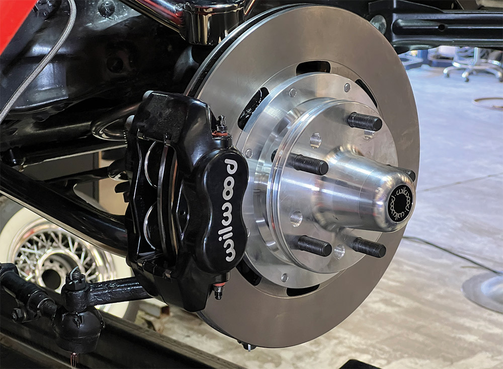
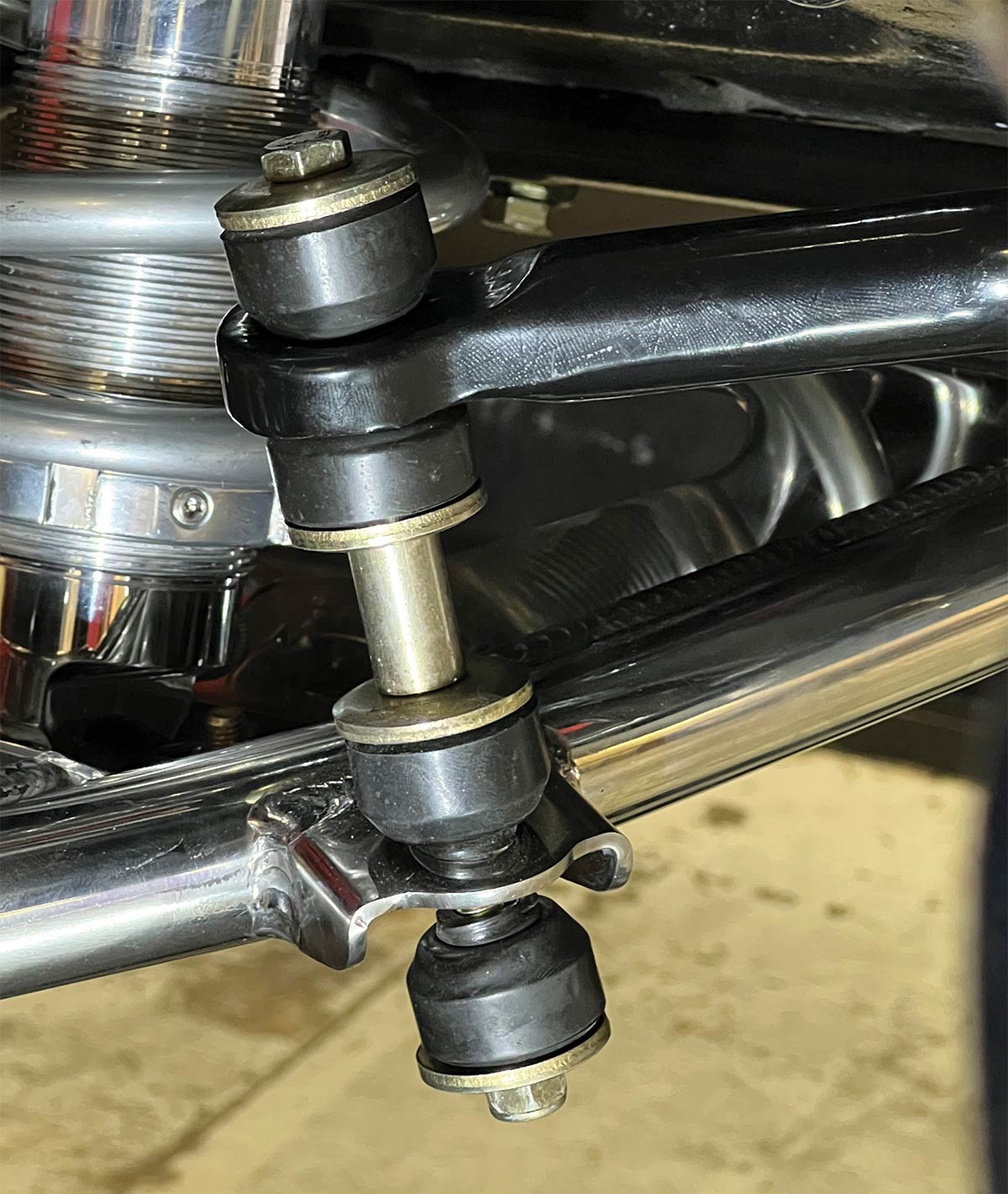
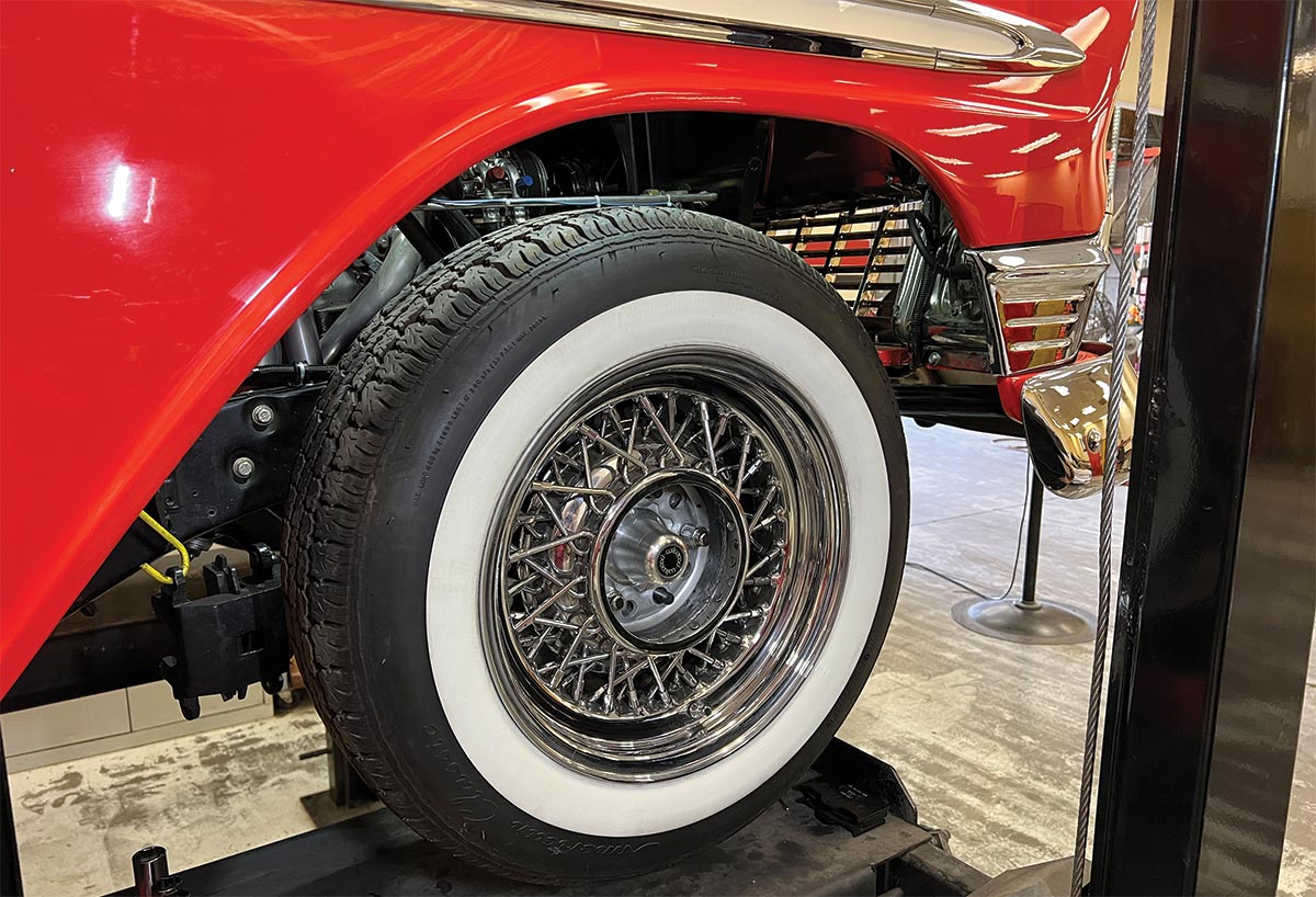
For this series of upgrades, the guys at Hot Rods by Dean called Heidts, as the Illinois-based company is known for its Tri-Five suspension components. With numerous options on the table, the Nomad would receive Heidts (PN CA-203-M) polished stainless steel upper and lower control arms, adjustable coilovers (PN CB-120), drop spindles (PN SP-002-A), and Wilwood Dynalite 12.19-inch disc brakes. This is a large improvement over the car’s existing setup, which consists of stamped steel lower control arms, generic tubular upper control arms, conventional coil springs, and ’80s GM disc brakes. While this setup offered many miles of service, it was time for an upgrade and the combination of Heidts and Wilwood parts were up for the task.
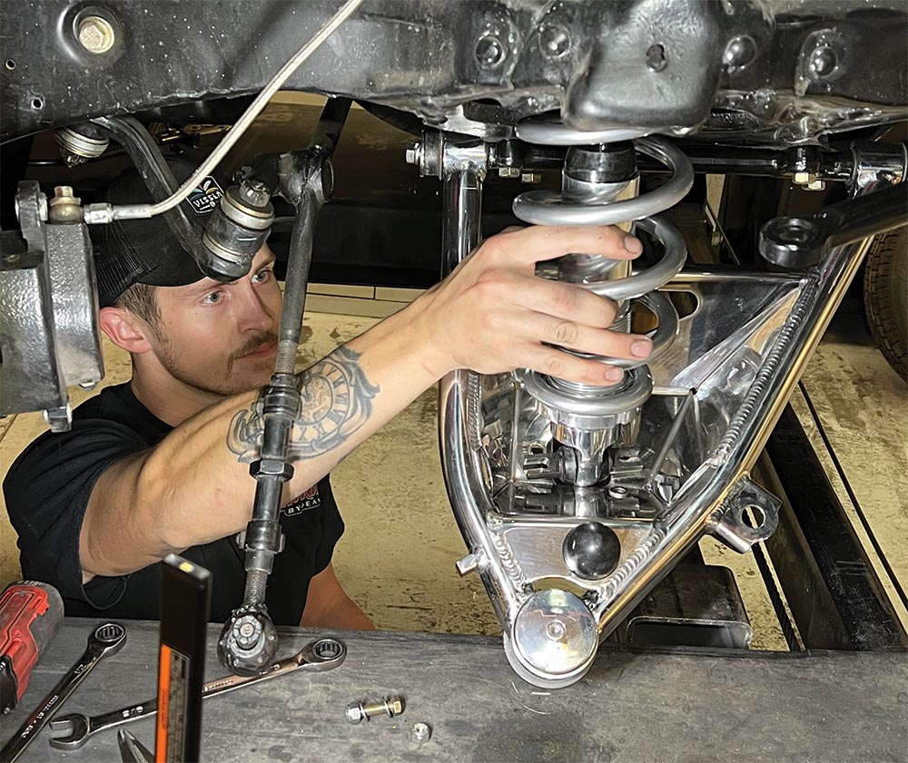
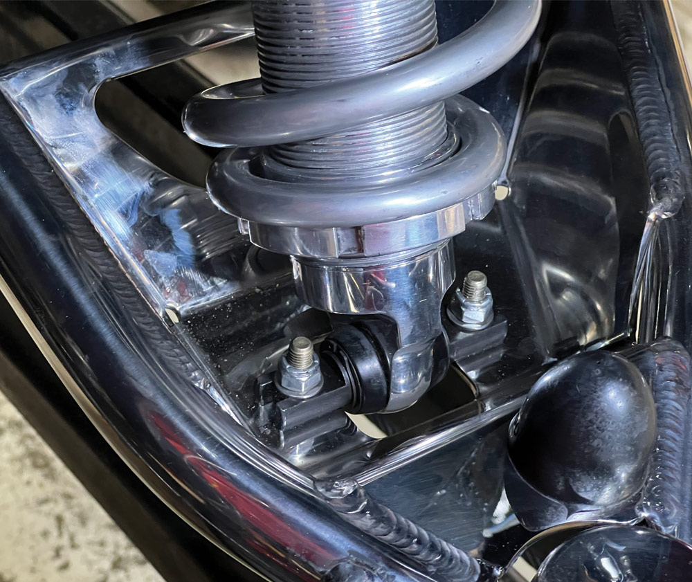
You can expect to install this collection of parts in a few evenings of shop time, as all the parts simply bolt in place of the originals. Obviously, painting and cleaning add to the time line, but you can expect a straightforward install with the components featured in this article. It made a huge difference in the stance and ride quality on this classic Nomad, and we’ll be ready to tackle the four-bar rear suspension soon.

VOLUME 3 • ISSUE 26 • 2022