Modern Rodding TECH

InTheGarageMedia.com

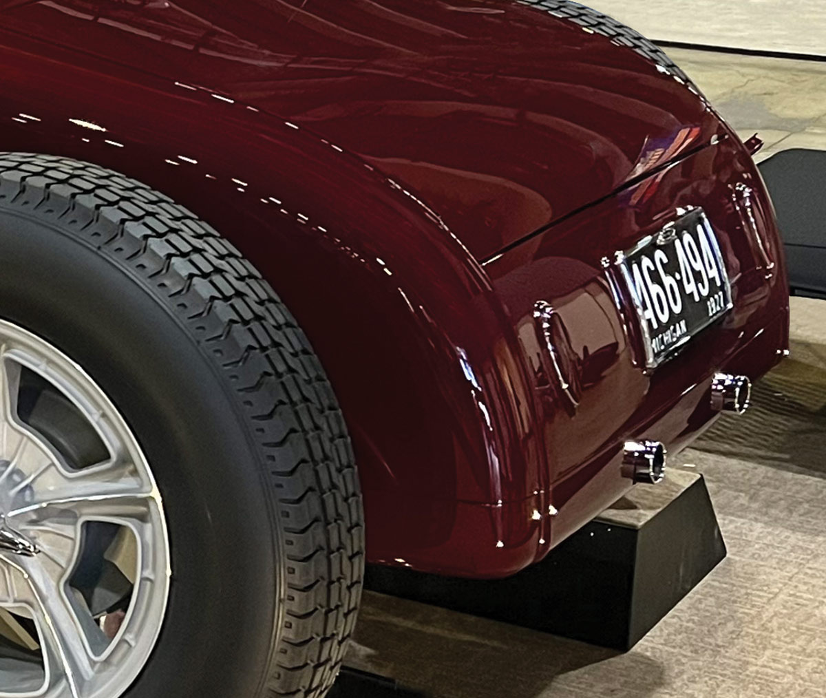
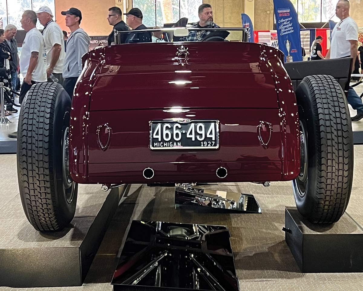
1. This is the tail end of a Shadow Rods XL27 body. This body has special reveals for the license and taillights.
Making a Roll Pan typographic title in black
The Art of Shaping Metal
By Ron Covell Photography by Jon Hall & Dave Autin
J

on Hall is the founder of Shadow Rods, a company that makes the XL27 body. This body has the basic shape of a ’27 Ford roadster but has been subtly enlarged to give more interior space and is tailored to fit perfectly on a ’32 Ford frame.

Hall recently finished a personal roadster project that features some unique modifications. It was a very strong contender for the America’s Most Beautiful Roadster award at the Grand National Roadster Show in Pomona, California. In this article, we’ll take an in-depth look at how the perfectly proportioned roll pan was made for the rear of the body.

The bottom edge of this body is completely flat, which provides a nice mounting surface for the roll pan. The center body pieces are bolted together on the rear of this body, just like the original Ford body was, and there is a crisp parting line next to the bead at the edge of the decklid. Jon wanted to continue this parting line down into the roll pan to give the design continuity; a lot of work went into fabricating the parts in such a way that the edges fit together with precision, mimicking the look of factory parts.

When making sheetmetal parts that bolt together, usually each part has a flange at 90 degrees to the face, and the fasteners go through these flanges. While it is possible to weld flanges directly to the edges of a panel, there are problems with doing it that way. Welding almost always causes distortion, and it’s very difficult to resolve the distortion when the weld is on a corner. If you look carefully at how this roll pan was designed, you’ll see that many of the flanges were created by bending them on a brake. This can only be done on flat panels, so you will see that on some of the critical edges of the roll pan, like the ones on the curved panels below the rear panel of the body, flat pieces of 19-gauge metal had flanges shaped over specially made hammerforms, creating a flange about 1/2-inch wide. These short flanges were then butt-welded to the edges of the panels. This puts the weld in a place where it can be worked with a hammer and dolly and it leaves a nice, uniform edge on the corner where the flange meets the face of the panel.

It can be challenging to make a roll pan with adequate stiffness, since they often attach only on the upper edge. Jon’s crew built a very clever bulkhead that spans the pan near the center, which strengthens the entire structure.

It takes an exceptional team to build a car like this. Jon Hall, Dave Autin, Randy Norton, Ashley Root, and Cliff Samual did the majority of the work at Shadow Rods.

If you examine the photos, you’ll see a lot of details showing excellent design coupled with masterful execution. This is just the combination you’d expect to see on a rod competing for top awards at major car shows.
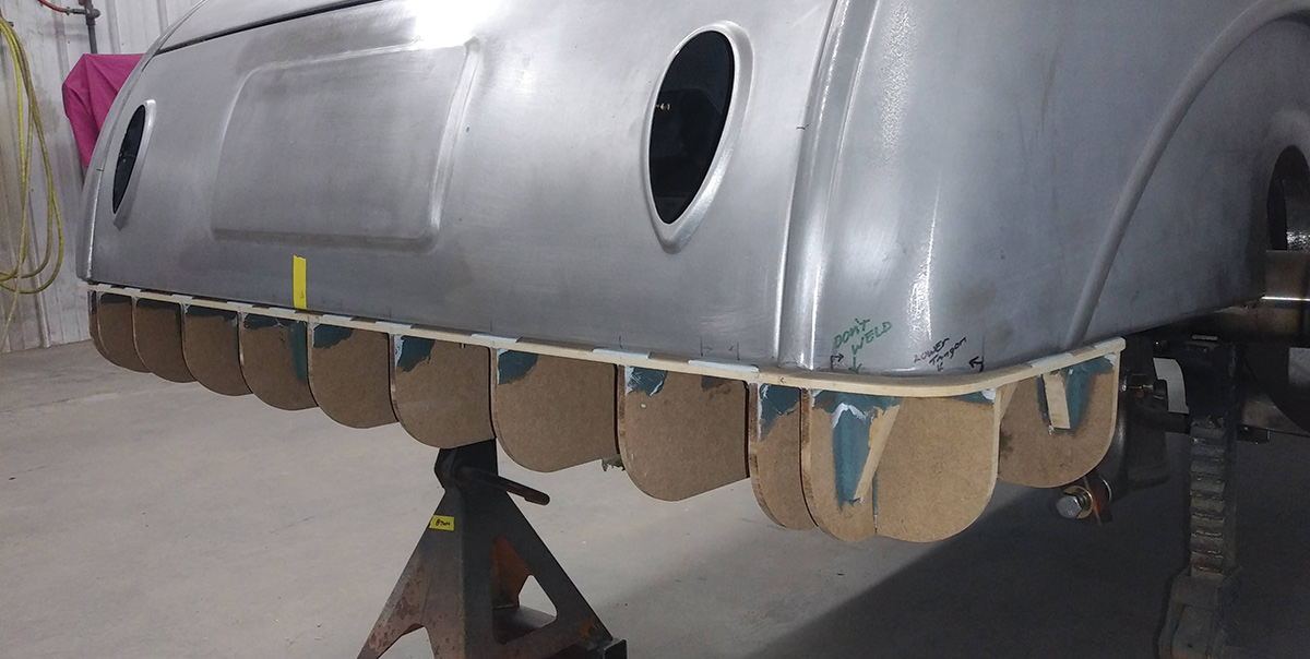
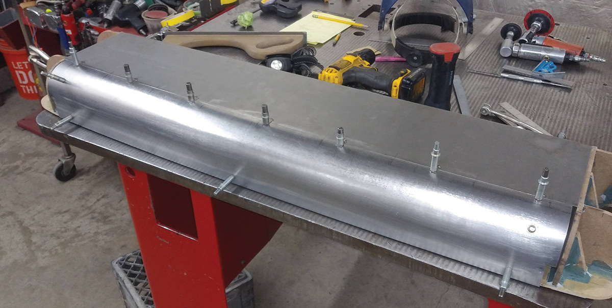
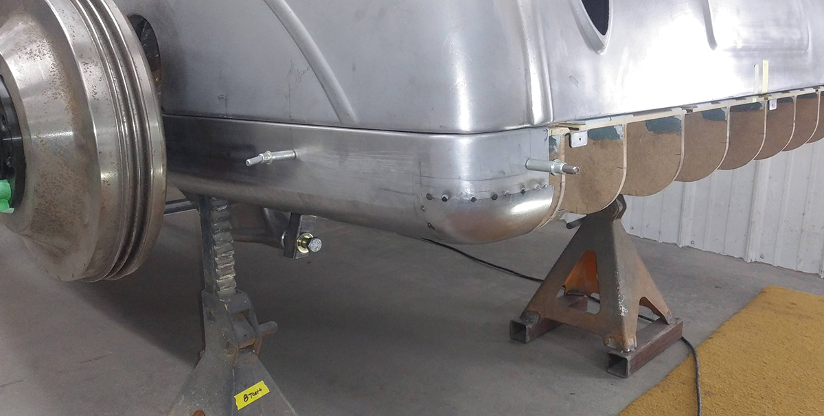
Before any metal can be shaped for the roll pan, a buck must be made to guide the work. This simple buck is made from 1/2-inch MDF.
2. Before any metal can be shaped for the roll pan, a buck must be made to guide the work. This simple buck is made from 1/2-inch MDF.
The center portions of the pan are shaped first. The front section is simply a flat piece of 19-gauge steel, and the curved portion has a slight compound curve, shaped on a power hammer.
3. The center portions of the pan are shaped first. The front section is simply a flat piece of 19-gauge steel, and the curved portion has a slight compound curve, shaped on a power hammer.
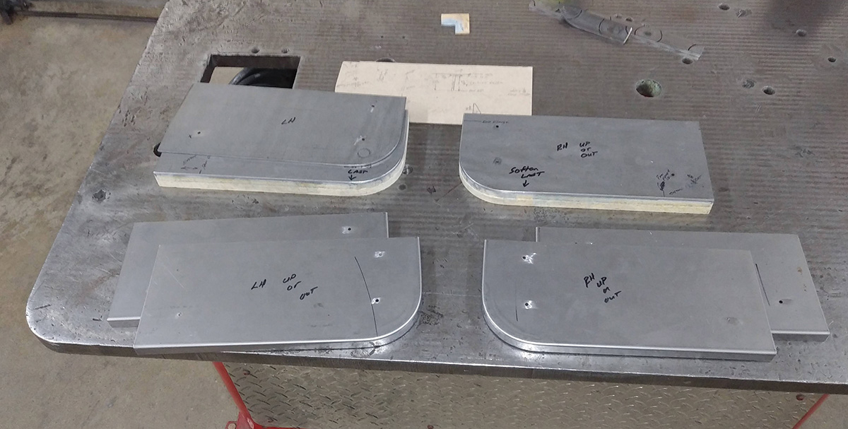
The roll pan will be made in three sections that bolt together. The flanges for joining the panels are created by hammerforming a 1/2-inch edge over custom-made forms.
4. The roll pan will be made in three sections that bolt together. The flanges for joining the panels are created by hammerforming a 1/2-inch edge over custom-made forms.
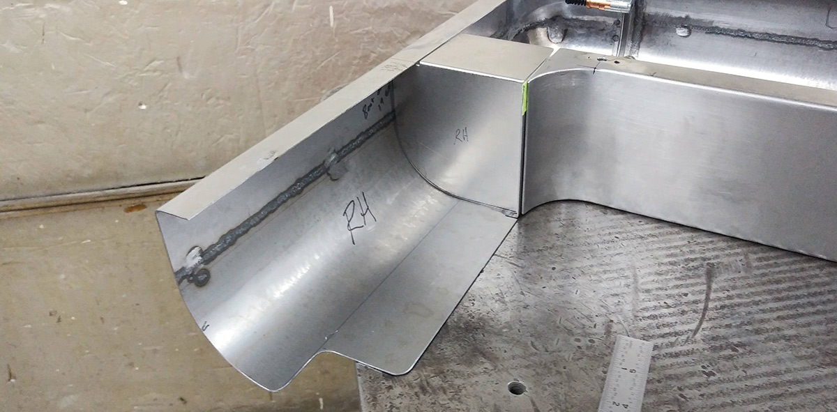
One of the hammerformed parts is shown tack-welded to the outer edge of the centersection. Placing the weld away from the corner keeps the corners crisp and uniform.
5. One of the hammerformed parts is shown tack-welded to the outer edge of the centersection. Placing the weld away from the corner keeps the corners crisp and uniform.
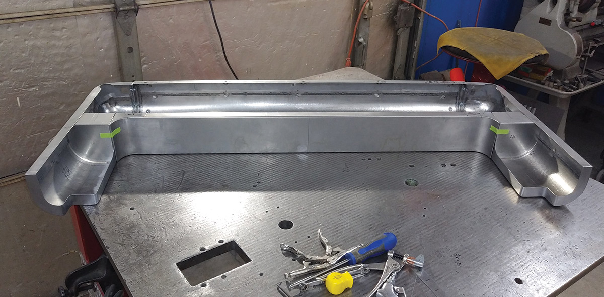
Here is the centersection of the pan fastened into place. After welding, the hammerformed endcaps were trimmed to leave a 1-1/4-inch flange.
6. Here is the centersection of the pan fastened into place. After welding, the hammerformed endcaps were trimmed to leave a 1-1/4-inch flange.
The sides of the roll pan were formed in several sections. The top part was formed as a straight angle, then curled to match the corner of the body.
7. The sides of the roll pan were formed in several sections. The top part was formed as a straight angle, then curled to match the corner of the body.
After the two large sections of the side pan were welded and metal finished, a domed corner piece was shaped and tack-welded into place.
8. After the two large sections of the side pan were welded and metal finished, a domed corner piece was shaped and tack-welded into place.
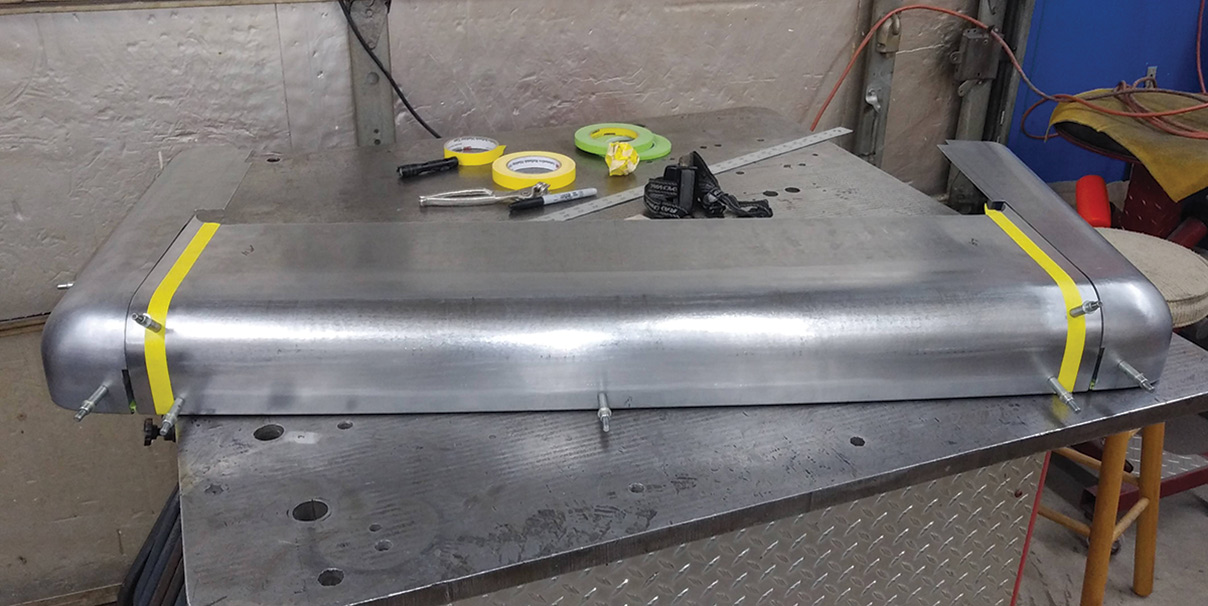
The three sections of the roll pan are trial-fitted together. As you can see, the fit is superb.
9. The three sections of the roll pan are trial-fitted together. As you can see, the fit is superb.
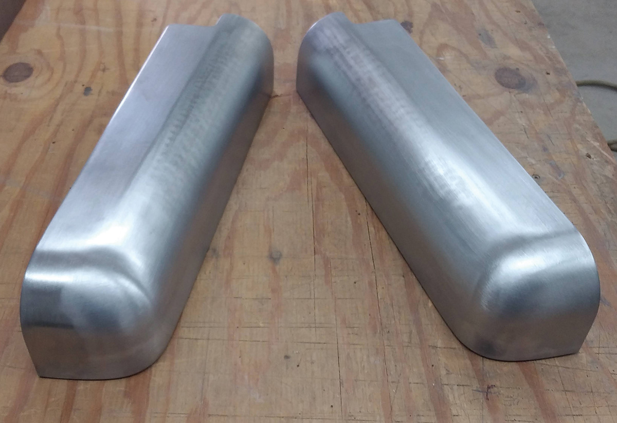
With the fitting verified, both side pans are metal-finished to perfection.
10. With the fitting verified, both side pans are metal-finished to perfection.
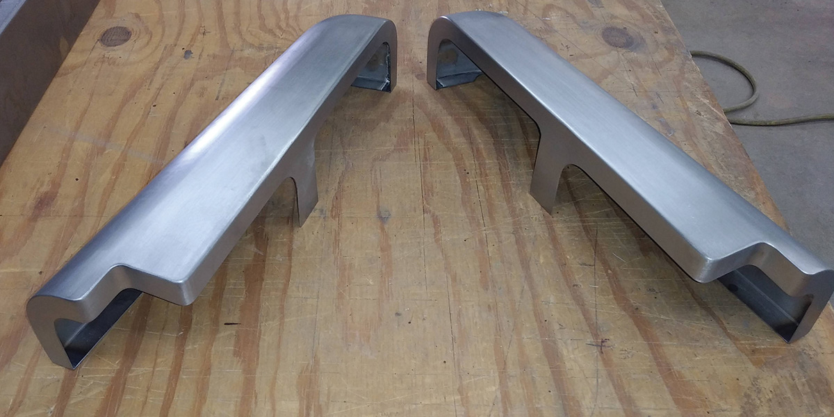
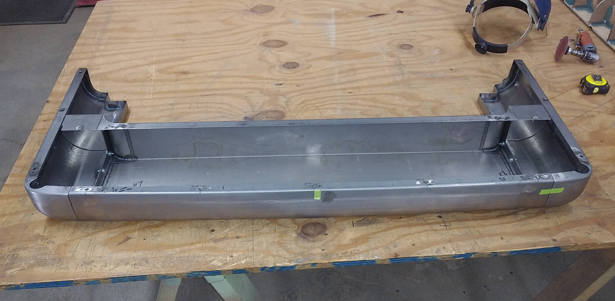
All the inner edges are given a uniform 1-1/4-inch flange, along with a tab for locating a stiffening bulkhead in the center.
11. All the inner edges are given a uniform 1-1/4-inch flange, along with a tab for locating a stiffening bulkhead in the center.
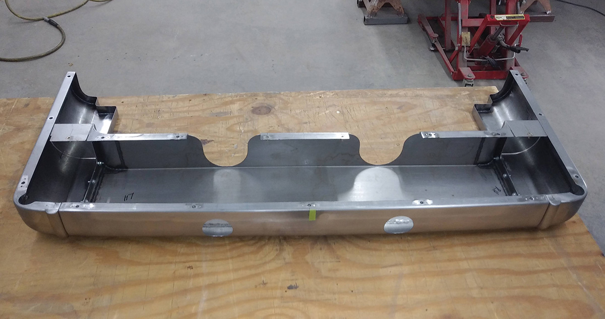
Here’s the top view showing how neatly all the pieces fit together.
12. Here’s the top view showing how neatly all the pieces fit together.
A closeup of the inner structure reveals the details of how the panels are joined.
13. A closeup of the inner structure reveals the details of how the panels are joined.
This view from the rear shows the details of the center bulkhead.
14. This view from the rear shows the details of the center bulkhead.
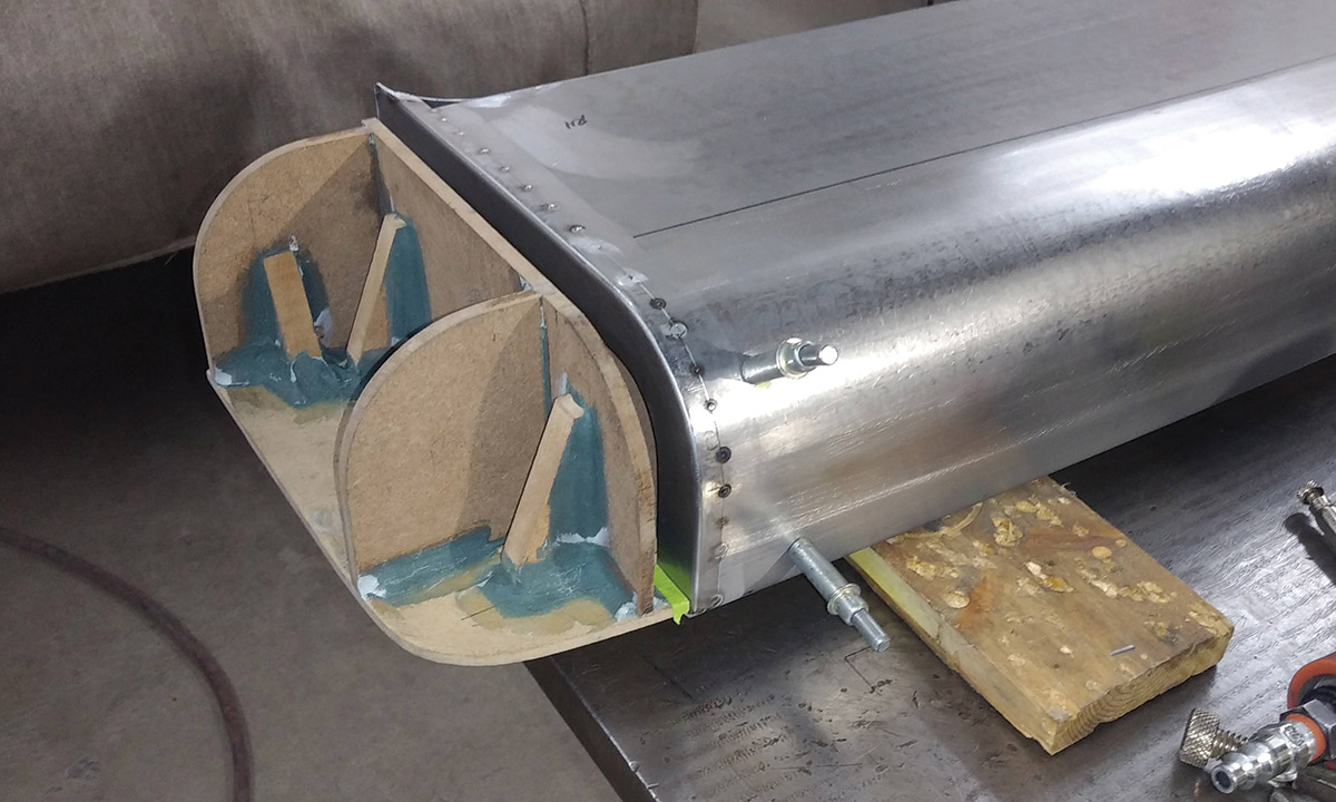
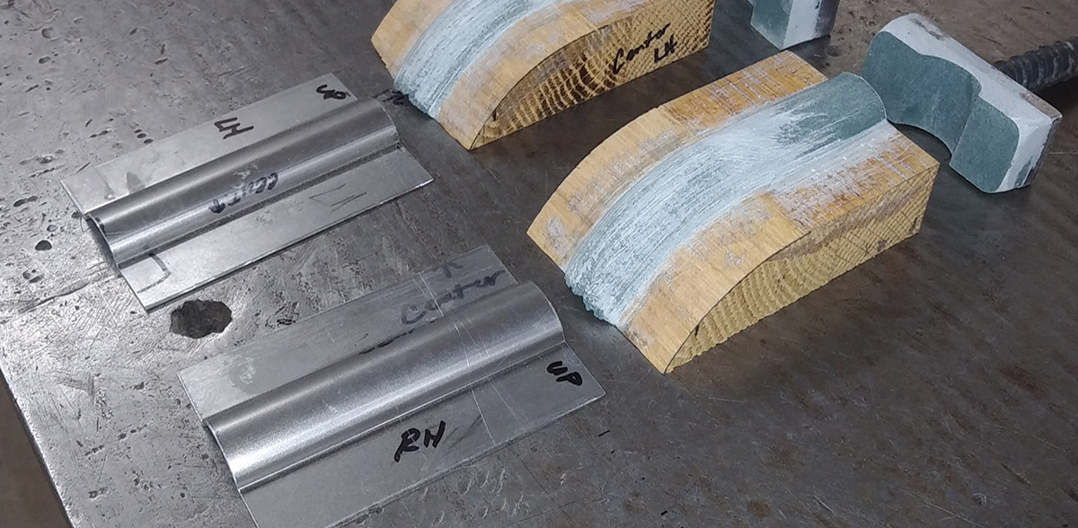
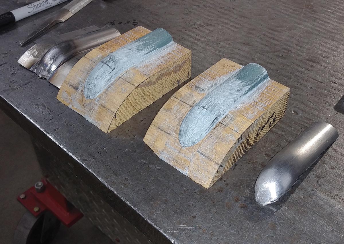
A decision was made to extend the body lines down onto the roll pan. Forms were made from wood and a filled epoxy resin to shape the extension pieces.
15. A decision was made to extend the body lines down onto the roll pan. Forms were made from wood and a filled epoxy resin to shape the extension pieces.
After the forms were hand-filed to perfection, sheetmetal was hammered against them to make the spear-shaped extensions.
16. After the forms were hand-filed to perfection, sheetmetal was hammered against them to make the spear-shaped extensions.
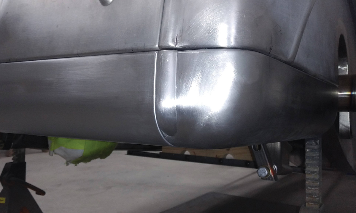
With the spears welded into place and metal finished, they give the roll pan a much more refined look.
17. With the spears welded into place and metal finished, they give the roll pan a much more refined look.
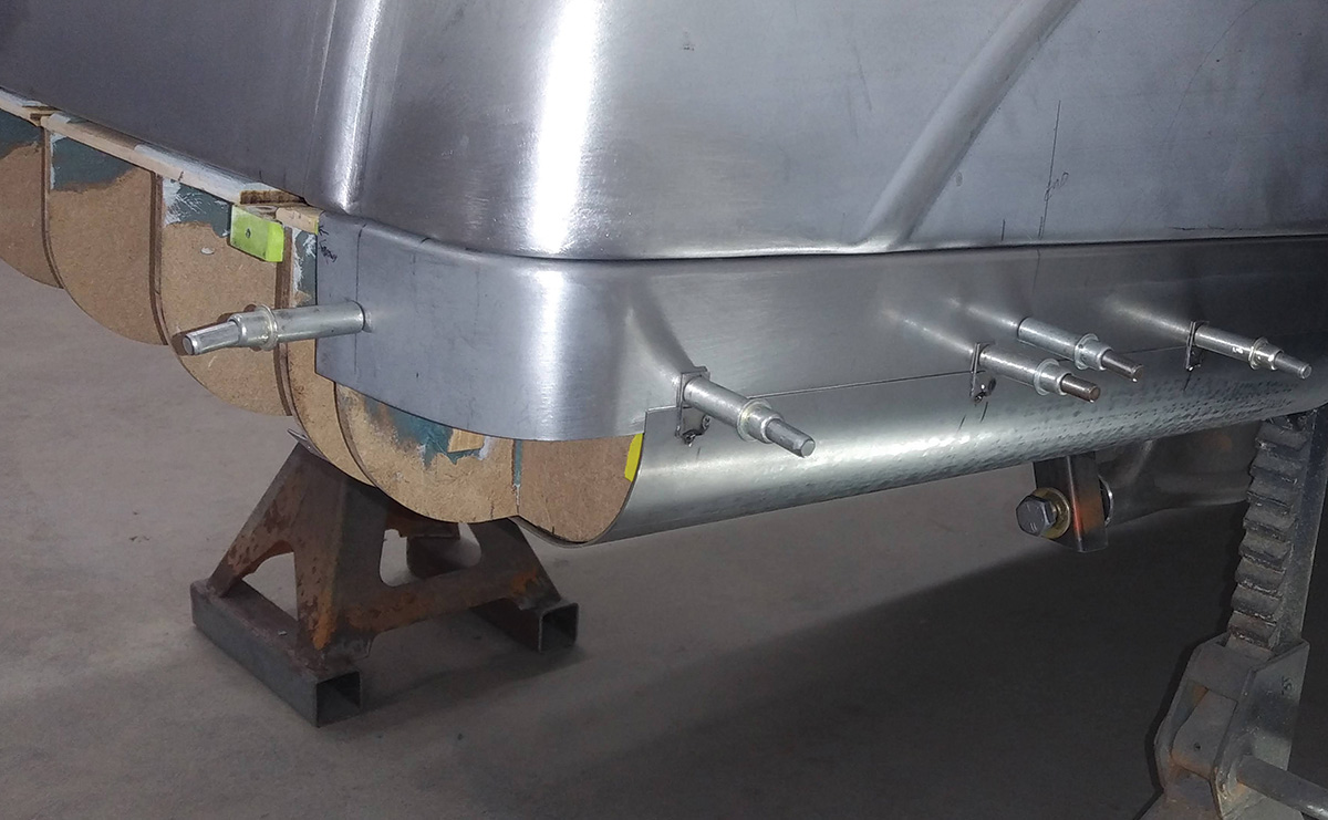
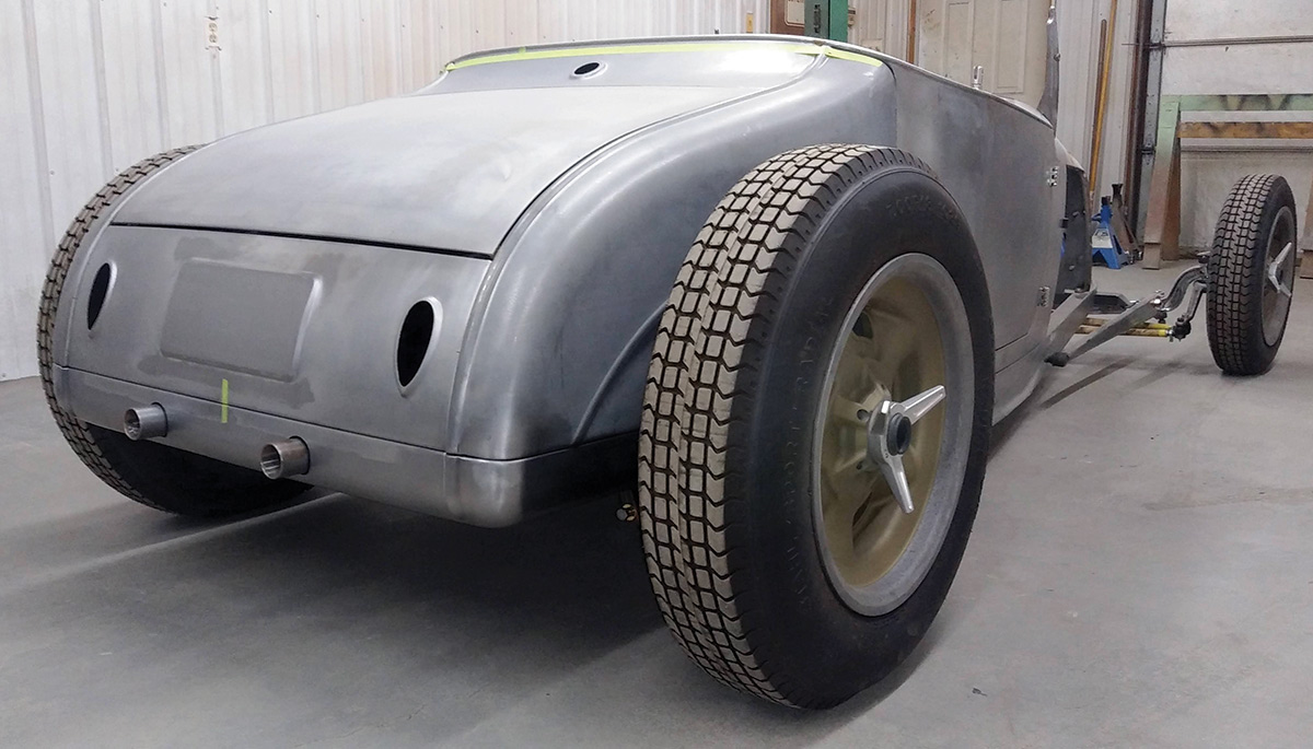
After the exhaust system was completed, the roll pan was relieved to make room for the exhaust pipes.
18. After the exhaust system was completed, the roll pan was relieved to make room for the exhaust pipes.
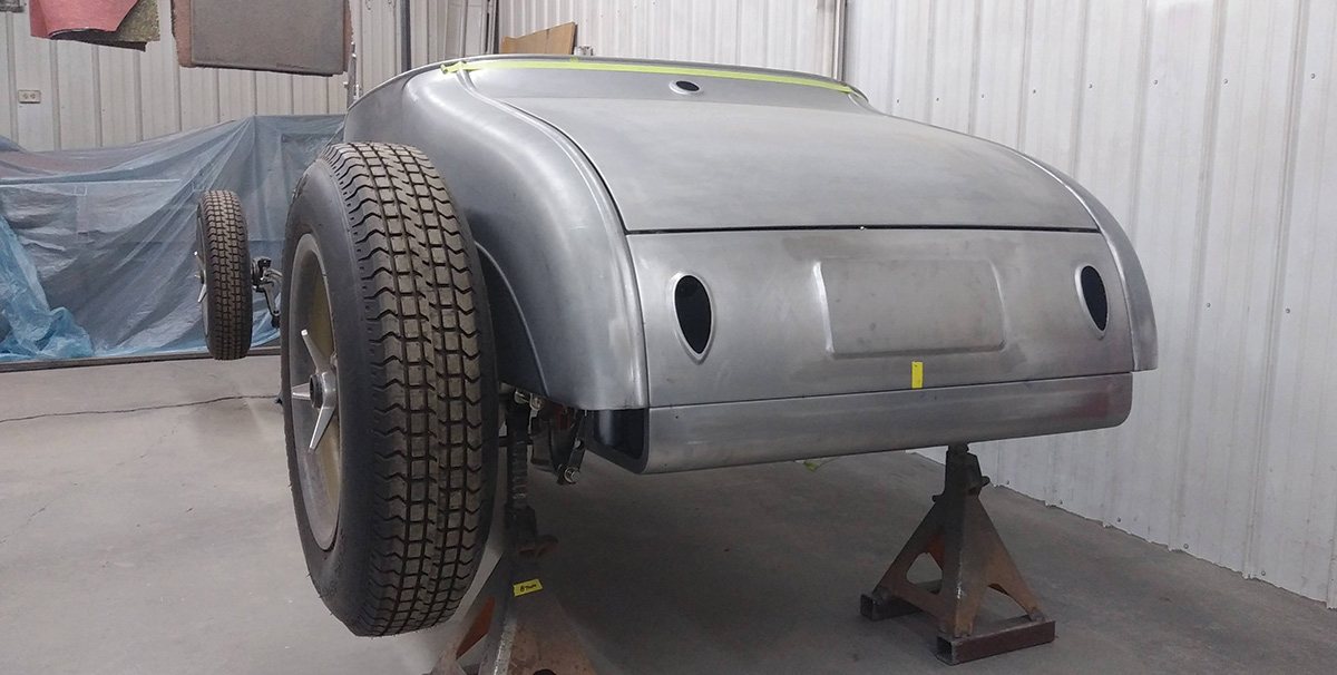
With the roll pan installed, you can get a better feel for the proportions of the car.
19. With the roll pan installed, you can get a better feel for the proportions of the car.
The final assembly and painting were done by Greening Auto Company in Cullman, Alabama. Here can see just how much this roll pan adds to the design of the car.
20-21. The final assembly and painting were done by Greening Auto Company in Cullman, Alabama. Here can see just how much this roll pan adds to the design of the car.
GREENING AUTO COMPANY
(256) 352-8700
greeningautocompany.com
SHADOW RODS
(989) 754-1927
shadowrods.com
Modern Rodding

VOLUME 4 • ISSUE 33 • 2023