Modern Rodding TECH

InTheGarageMedia.com

"Laying the Foundation"
1. Every project starts with a vision. Eric Black’s renderings set the stage for this chopped, lengthened, and subtly pie-wedged beauty.
’35 Chevy Coupe Gets the Upgraded Chassis Complete With 8-Stack Injection
By Ron Covell Photography by Rodger Lee Artwork By E. Black Design
O

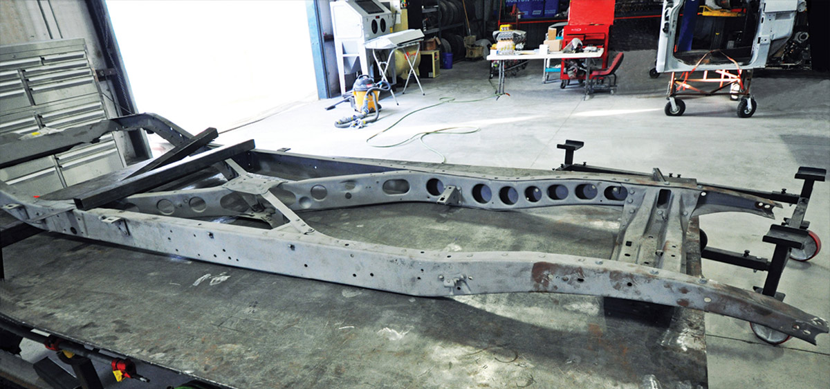
n any automotive project the chassis is the foundation that holds all the components together. Sometimes a stock chassis can be used, but when the suspension and drivetrain are updated, the chassis usually needs to be strengthened and reconfigured.

This is the first in a series of articles about Greg Heinrich’s outstanding ’35 Chevrolet coupe being built by Ironworks Speed & Kustom, in Bakersfield, California. This is a multi-year, no-holds-barred project and we think you’ll enjoy seeing the bleeding-edge design and fabrication lavished on every component.

The body modifications on this project are subtle, and Eric Black, of e. Black Design Co. was called in at an early stage to make renderings, which was key to keeping all the modifications harmonious and on track. The top has a sweet chop, with the A-pillar laid back, the rear of the body is lengthened around 2 inches, the rear wheelwells are raised, and the body has a wedge section–lowering the front of the grille shell a tasty amount. The fenders are re-contoured for the larger wheels and tires, and there are dozens of unique features you’ll see in future articles, making use of the latest technology available.

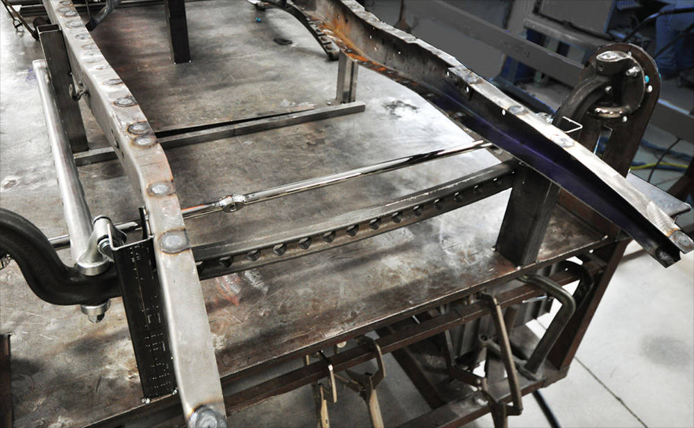
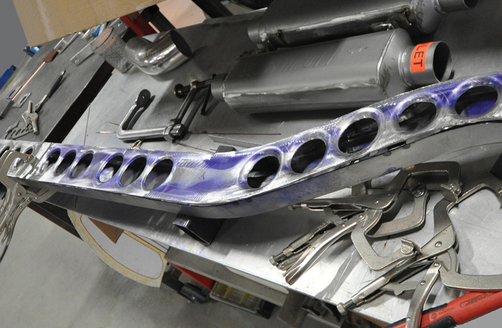
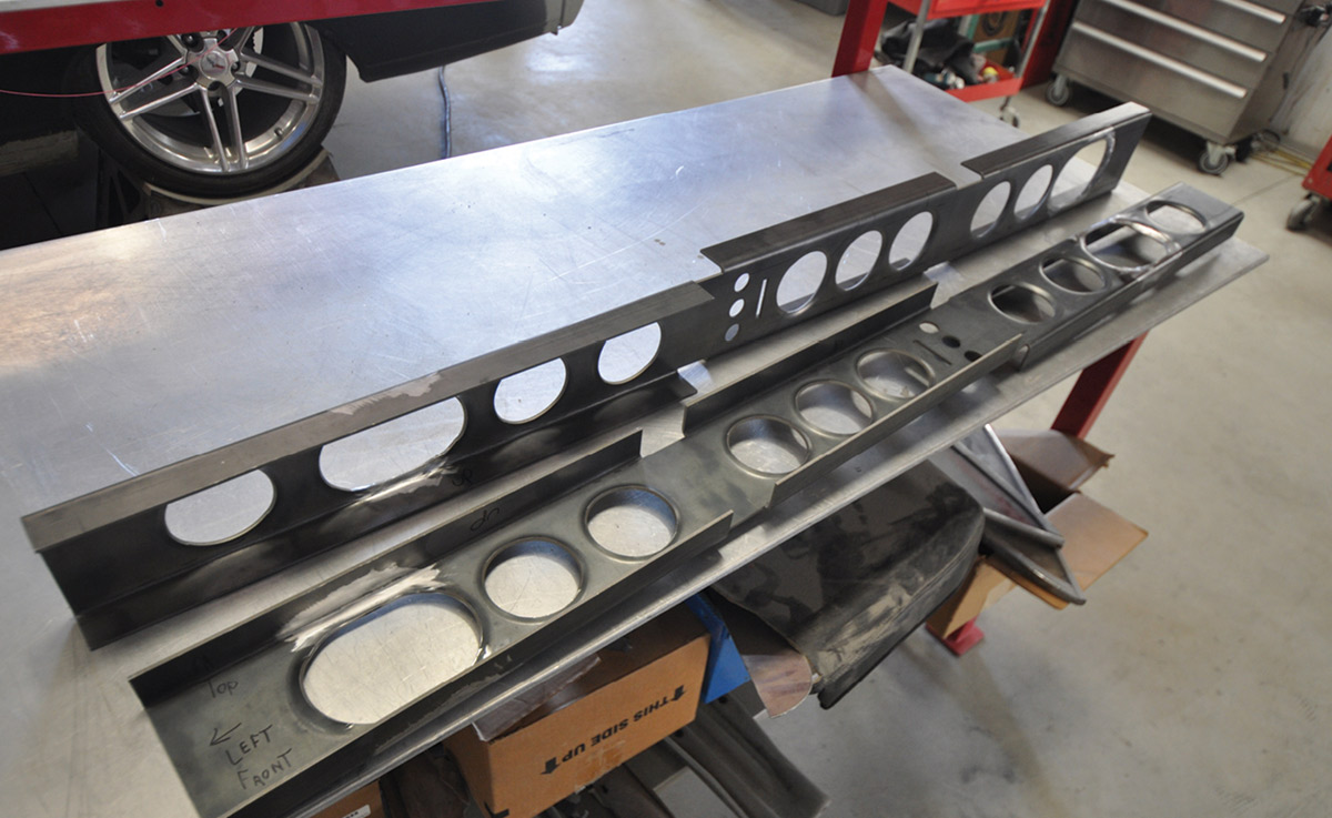
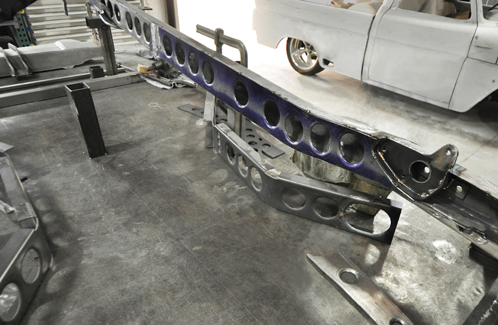
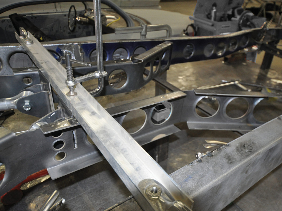
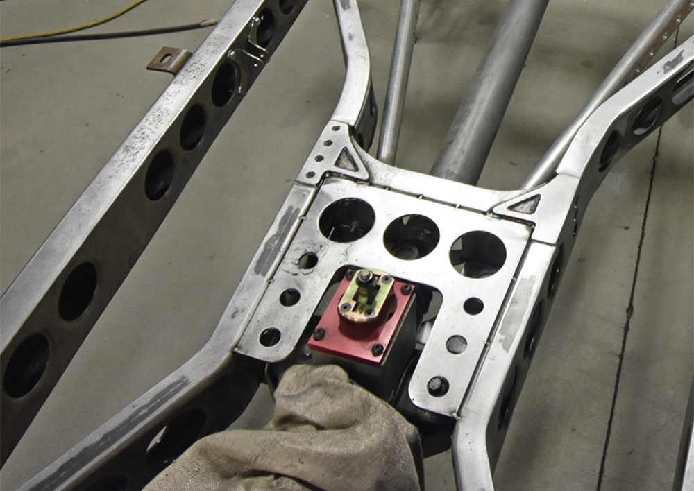
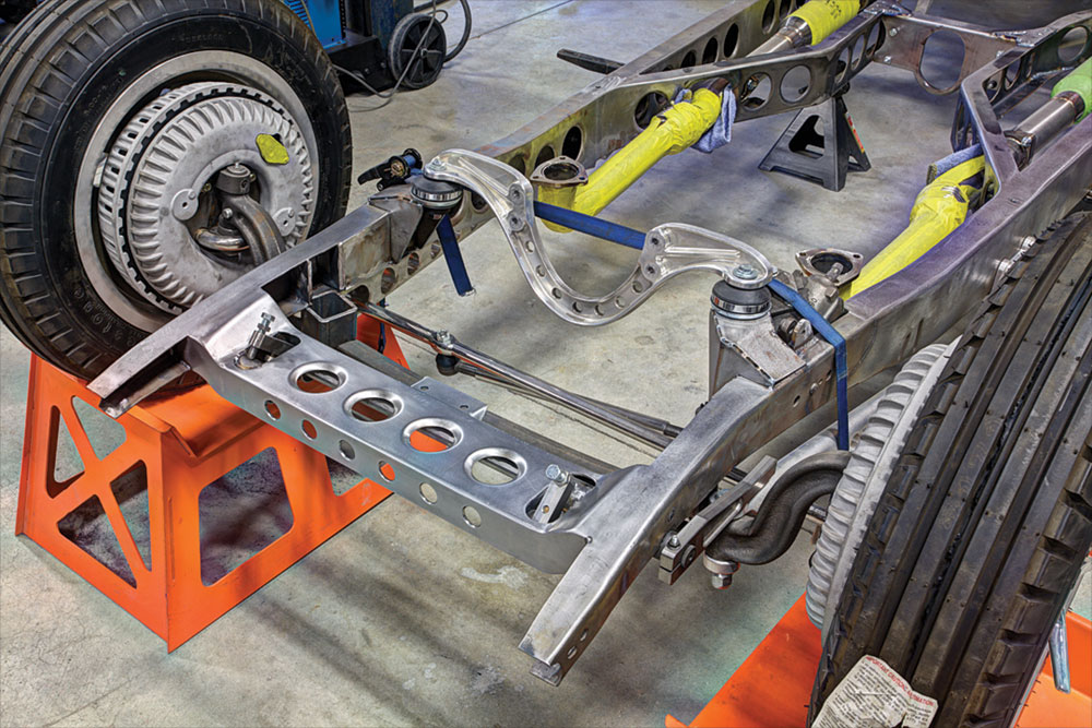
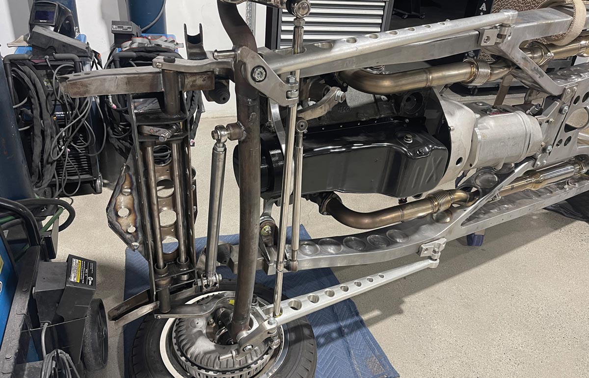
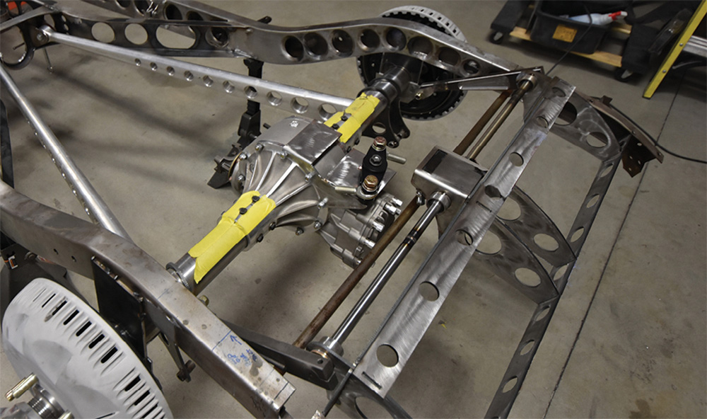
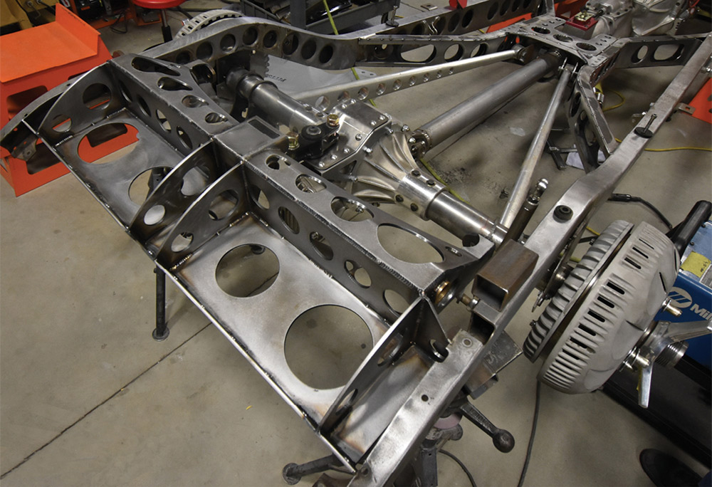
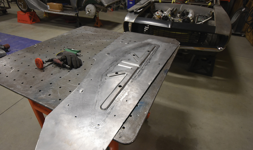
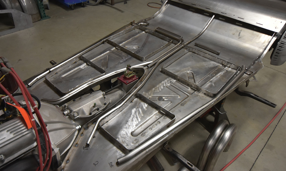
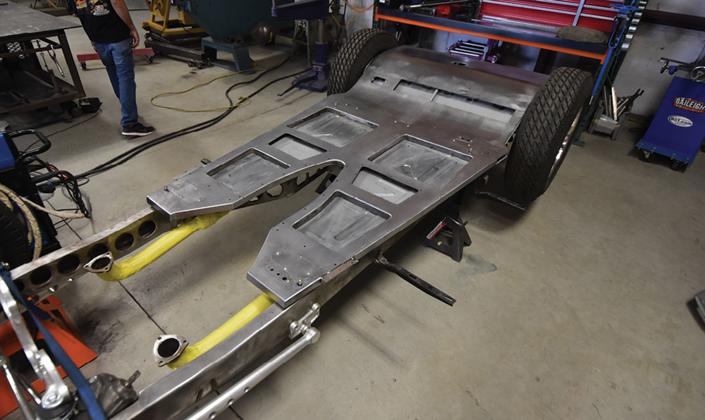
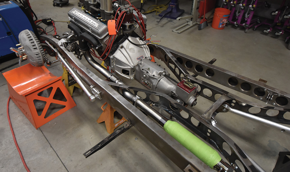
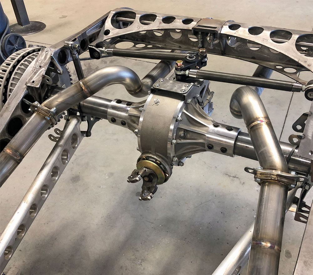
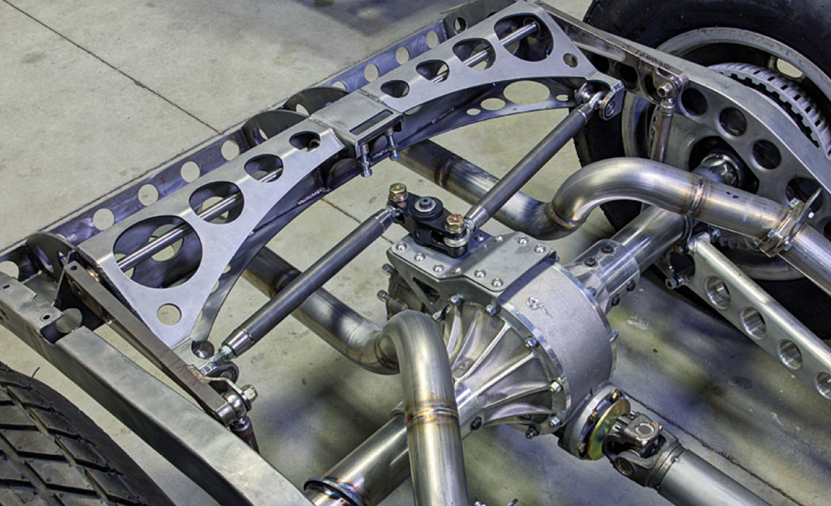
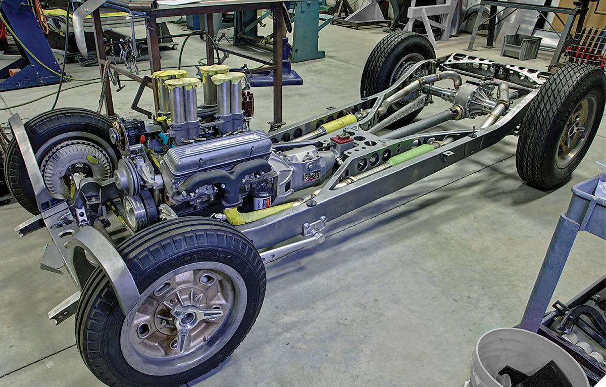
The car has cross torsion bars, both front and rear, with a dropped tube axle in front, and a Winters quick-change in the rear. New boxing plates and a new X-member are fitted to the framerails, liberally perforated with “speed” holes.

Johnson’s Hot Rod Shop’s vintage-looking disc brakes are used on all corners, and their billet radius rods are used front and rear.

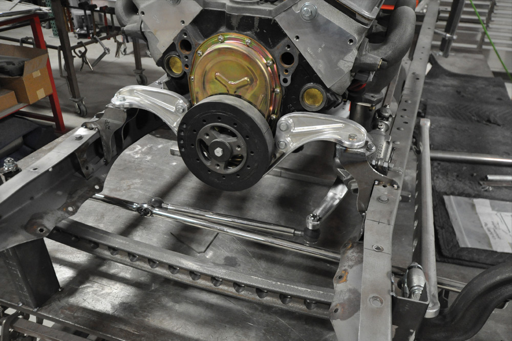
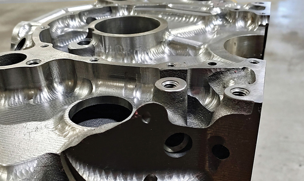
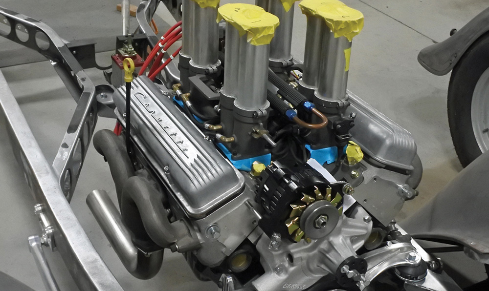
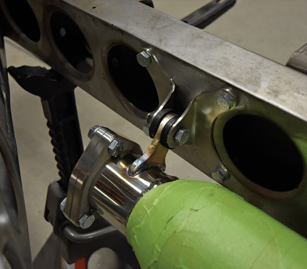
The engine is a potent small-block Chevrolet with aluminum heads featuring a Holley electronic injection and ECU adapted to Hilborn castings and is fitted to a Bowler TKX five-speed transmission. The block was completely CNC machined to smooth the castings, removing any extra mass and unnecessary features. The exhaust is all stainless and is carefully routed through the chassis, so nothing hangs below the framerails.

The Ironworks crew is using CAD design, coupled with 3-D printing and CNC machining to make many of the most challenging components for this build. This technology opens a lot of doors for efficiently designing intricate parts. Once a design is made, it can be printed to make a trial part for fitting and testing before it is CNC machined from billet. It is relatively easy to make changes in the CAD model, so often several iterations of a design will be printed and tested before committing to metal. There is no limit to the intricacy of the details incorporated, and the parts can be made with tolerances simply not possible with hand-fabricated parts. This type of fabrication used to be limited to NASA-level work, but the technology has become much more affordable and user-friendly in recent years.

This first article will focus on the chassis build, and next time we’ll dive in for some of the body modifications. Hang on, we think you’ll love this journey!

Stock stripped coupe frame
2. This is the stock frame–stripped, sandblasted, and ready for action.
Initial metalwork done on frame
3. The first step was removing the riveted-in crossmembers and boxing plates, welding up all unnecessary holes, and positioning the ’rails on a sturdy chassis table.
Boxing plates with holes
4. New boxing plates were made with tastefully dimpled holes. Strategic areas were left solid for attaching the new X-member and other important features.
Skeletonized X-member on bench
5. This is the start of the X-member, with flanges formed on a press brake. The oval holes are for the exhaust system to pass through.
X-members mocked into place
6. The X-member is carefully bent to its final configuration. Note the neat pocket in the framerail for the steering box. The framerails were lengthened before boxing.
X-member clamped into place before welding
7. Here the X-member is being checked for fit before tack welding. Temporary crossmembers hold everything in alignment.
Additional bracing added to X-member
8. The open channels were boxed, and several more pieces were added to the X-member to give it tremendous strength.
Engine mount points mocked up on framerails
9. In the front of the chassis, a beautiful one-piece aluminum motor mount is attached to the engine and steel mounts are being mocked up on the framerails.
Torsion bars and crossmember on front end
10. Torsion bars are used on the front axle, and a low-profile crossmember was constructed to house the bars and adjusters.
Chassis flipped on its side showing axle linkages and underside
11. This view shows how compactly the torsion bars are packaged, along with the linkage that connects them to the axle and the Panhard bar.
Rear end and axle
12. Torsion bars are used in the rear, too. With the adjusters in the center. The crossmember is mocked up here.
Rear skeletonized crossmember in place
13. The rear crossmember is nearly completed here. Lots of holes are used to keep the weight to a minimum, and they add a lot of visual interest.
Floorpan being shaped on bench
14. This car has an unusually well-detailed floorpan. The construction is just started here, with a small-embossed panel being fitted into one side of the floor.
Floorpan installed onto frame
15. The floor is a sandwich construction. Most of the lower pieces have been fitted together here in preparation for attaching the top layer.
Top floor pan welded in
16. Here is the floor with the top layer welded into place. Note how snugly it fits the frame.
Close up of machining done on engine block
17. The engine block was smoothed out and lightened by CNC machining. Any unnecessary bumps and features were removed.
Built engine with taped velocity stacks
18. Holley electronic injectors were adapted to Hilborn castings.
Exhaust in place between framerails
19. With the frame basically completed, the exhaust system was fabricated. Note that no part hangs below the chassis, and that the large tubing fits extremely well into the openings provided.
Custom fabbed hanger for exhaust
20. Look at this beautifully designed and fabricated hanger for the exhaust system.
View of exhaust routed above rear axle
21. In the rear of the chassis, the exhaust routing is more complicated where it passes over the rear axle. Still, everything fits beautifully and there is adequate clearance everywhere.
Custom Watts link mounted on top of rear diff
22. Check out the unique, horizontally mounted Watts link used to keep the rear axle centered. This design is extremely compact and nearly out of sight from under the car.
Completed chassis with full drivetrain
23. The finished chassis is very strong, and is a thing of beauty. Next time we’ll look at some of the body modifications on this striking car.
Ironworks Speed & Kustom
(661) 399-8999
ironworksspeedandkustom.com
Modern Rodding

VOLUME 4 • ISSUE 29 • 2023