Modern Rodding TECH
InTheGarageMedia.com

 Photography by Tate Radford
oilover shocks have been around for a long time. It’s been so long that several unnamed Modern Rodding editors had a full head of hair when they first began to find favor with chassis builders. Initially, coilovers were only found on race cars, but it was our good friend, the late LeRoi “Tex” Smith, who has been credited with first installing them on a street rod. He hung a pair on the rear of his America’s Most Beautiful Roadster trophy–winning XR-6 in 1962 and coilovers have been with us ever since.
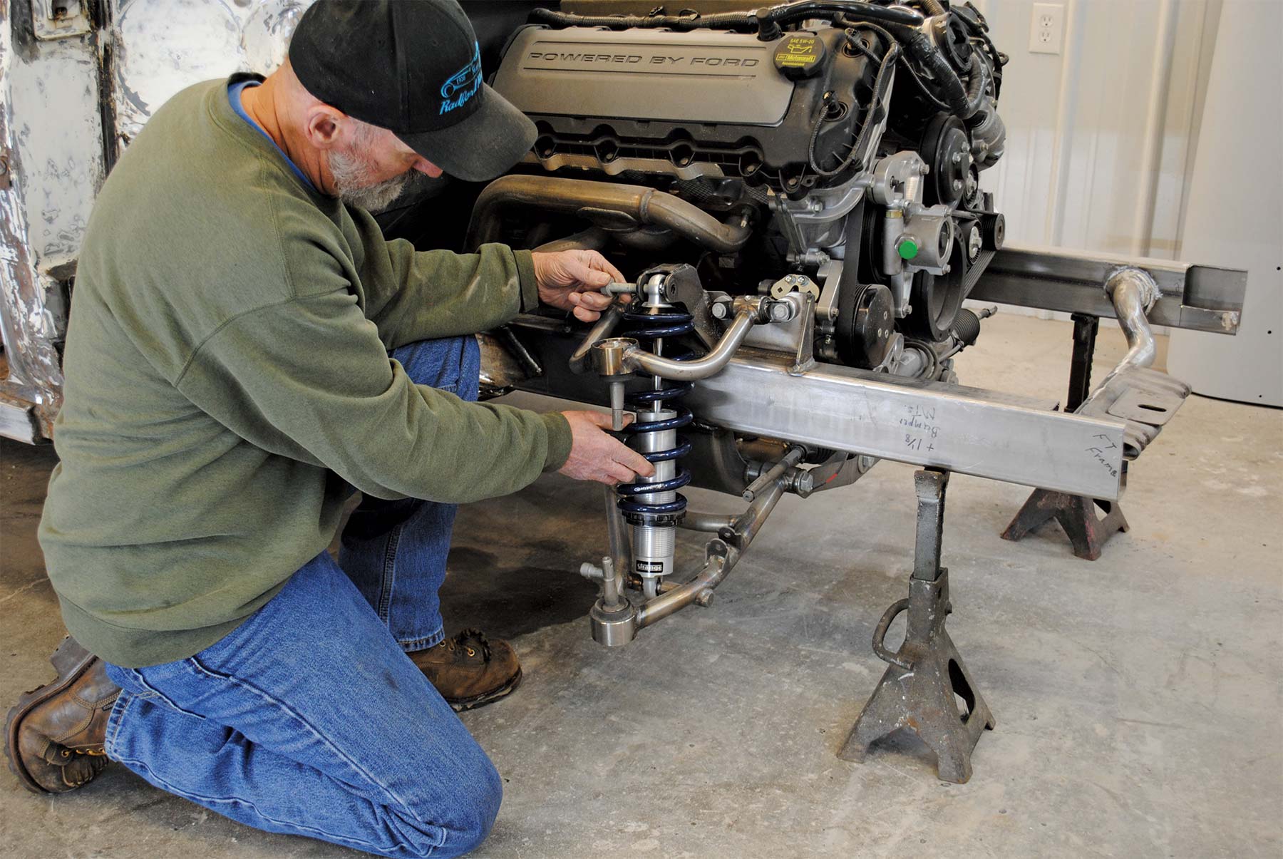
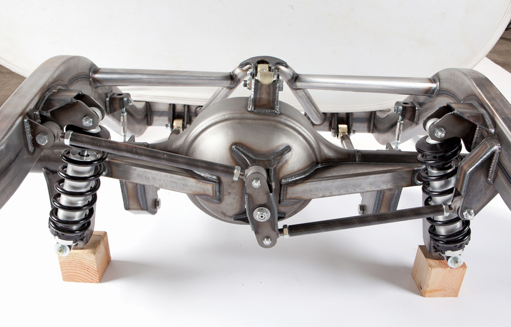
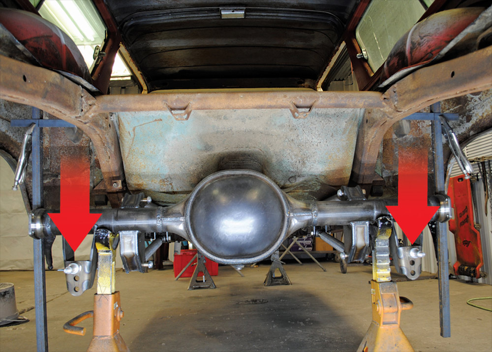
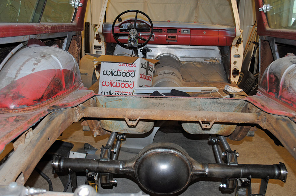
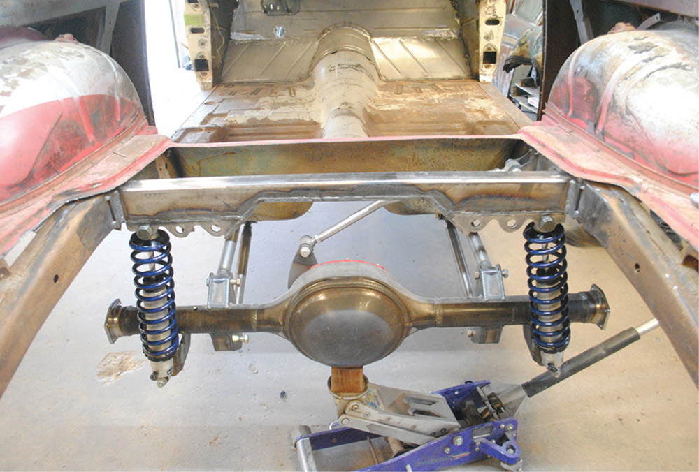
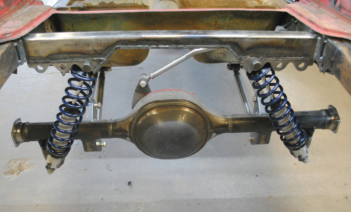
While coilovers have been popular on sports cars and smaller, prewar hot rods, they have also become popular for use on larger, heavier postwar cars, like Colin and Sue Radford’s ’57 Ford station wagon shown here. And why shouldn’t they be? It’s simply a matter of selecting the correct combination of shock absorber and spring to make them work as they should, and with help from Strange Engineering (SE) that’s what we did.
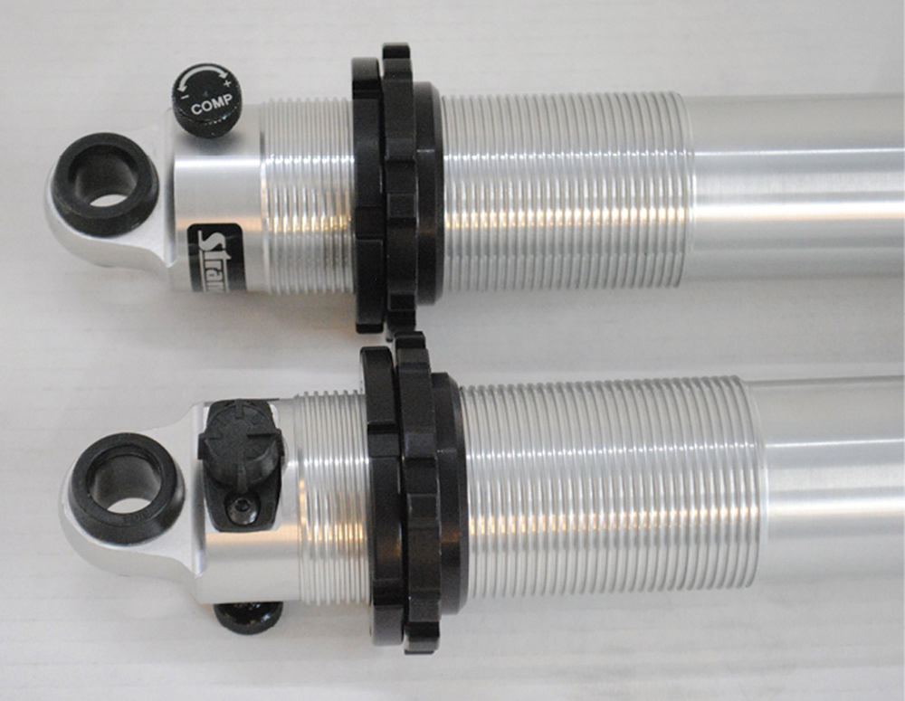
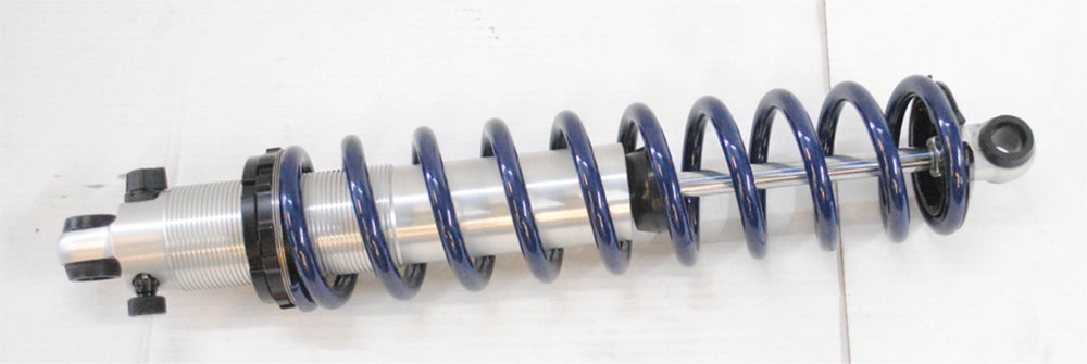
For decades SE has been a source for quality driveline and suspension components, including a comprehensive line of coilover shocks. To make selecting the correct coilovers easy Strange offers a chart with all relevant dimensions. For our application the front shocks used are single-adjustable (extension damping only) PN S5205 with the following specifications: extended length 15.40 inches, collapsed length (without the bumpstop) 10.76 inches, recommended ride height of 12.625 to 13.250 inches, and a stroke of 4.64 inches. In the rear, the double-adjustable shocks (extension and compression damping), PN S5007: extended length 19.15 inches, collapsed length (without the bumpstop) 12.64 inches, recommended ride height of 15.25 to 16.00 inches, and a stroke 6.52 inches.
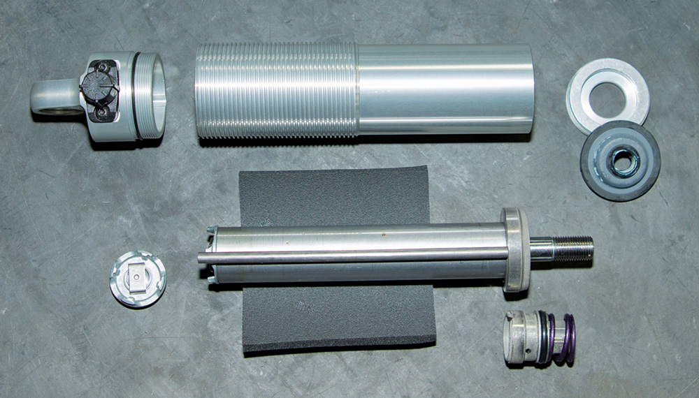
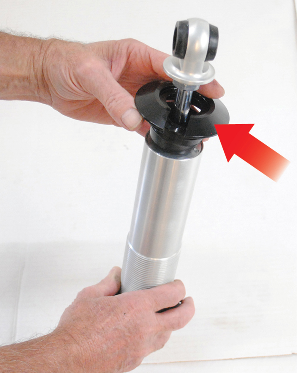
With the shock dimensions determined the next consideration was what springs to use. Strange offers quality Hyperco springs because they are cold wound from heat-treated chrome silicon (SAE 9254) wire. The ends are ground smooth, the springs are thermally stress relieved, and shot peened.
Coilover springs are identified by length, diameter, and spring rate. Length and diameter are determined by the shock absorber body, while spring rate is dependent on several factors, including vehicle weight and the intended use. Spring rate is simple enough; it’s the force required to compress the spring 1 inch measured in pounds. Hyperco springs are tested for spring rate, which is then stamped directly on the spring.
There are a variety of methods to determine spring rate, the problem is the requirements vary so greatly depending on the vehicle and its use that it’s virtually impossible to make useful spring recommendations. The basic goal is to have the shocks compressed roughly 40 percent with the car stationary, but the best way to determine the spring rate required is to use the program found on hypercoils.com.
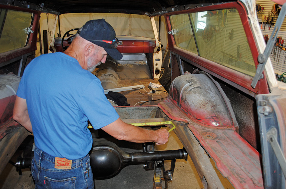
To use the spring rate program some basic information will be required. First and foremost is vehicle weight, specifically corner or wheel weight. The most accurate way to determine that is to axle weigh the vehicle. If that’s not possible, published overall curb weights are the next best thing, figure 55 percent of the total weight will be on the front, 45 percent on the rear. Divide the axle weight in half and you have the corner weight of the car. The next factor to consider is unsprung weight, which is the weight of the components not supported by the springs, such as the wheels and tires, brake components, half the weight of the control arms, rear axle assembly, and half of the coilovers. A good guesstimate of unsprung weight would be around 150 pounds.
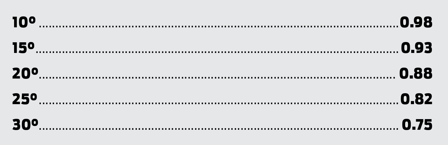
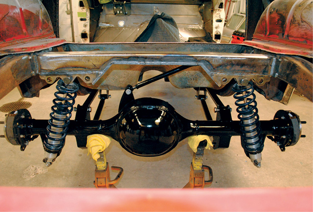
With all the information required, including length of the shocks at ride height, we plugged the numbers into the Hyperco calculator and it indicated 200-pound springs for the rear of the wagon. Keep in mind another consideration when selecting coilover springs is the mounting angle, so changing that angle will have an effect. The greater the installed angle, the stiffer the spring rate must be to support the same weight. A general guideline for reduction in effectiveness is:
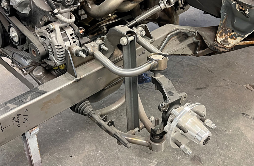
To determine what front springs to use on the ’57 the same basic information was required plus what is called the motion ratio. Think of the lower control arms as levers applied to the springs, which means stiffer springs would be required when compared to a solid axle (front or rear)—that’s motion ratio. For an independent front suspension, the distance from the control arm pivot point on the subframe (centerline of the bushing) to the point on the control arm directly under the center of the spring or coilover assembly will be required. In addition, distance from the control arm pivot point on the subframe to the centerline of the ball joint will also be necessary. With all the shock angle numbers entered into the Hyperco program we determined 550-pound front springs would be perfect.
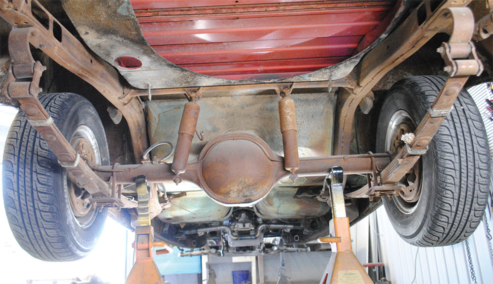
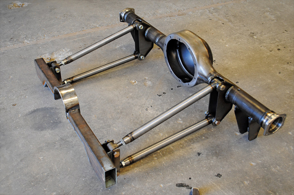
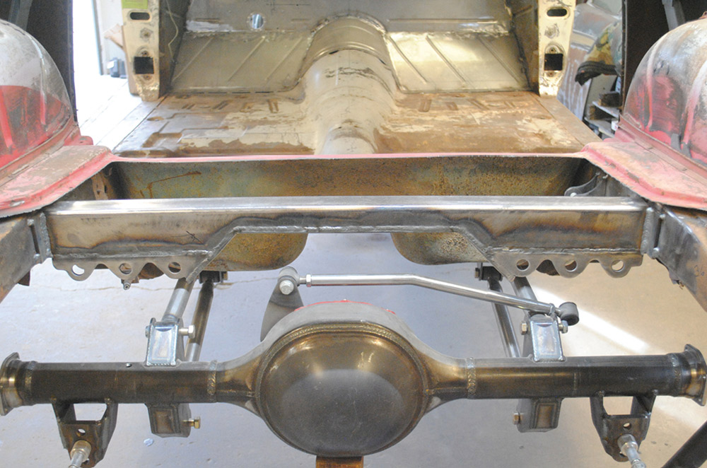
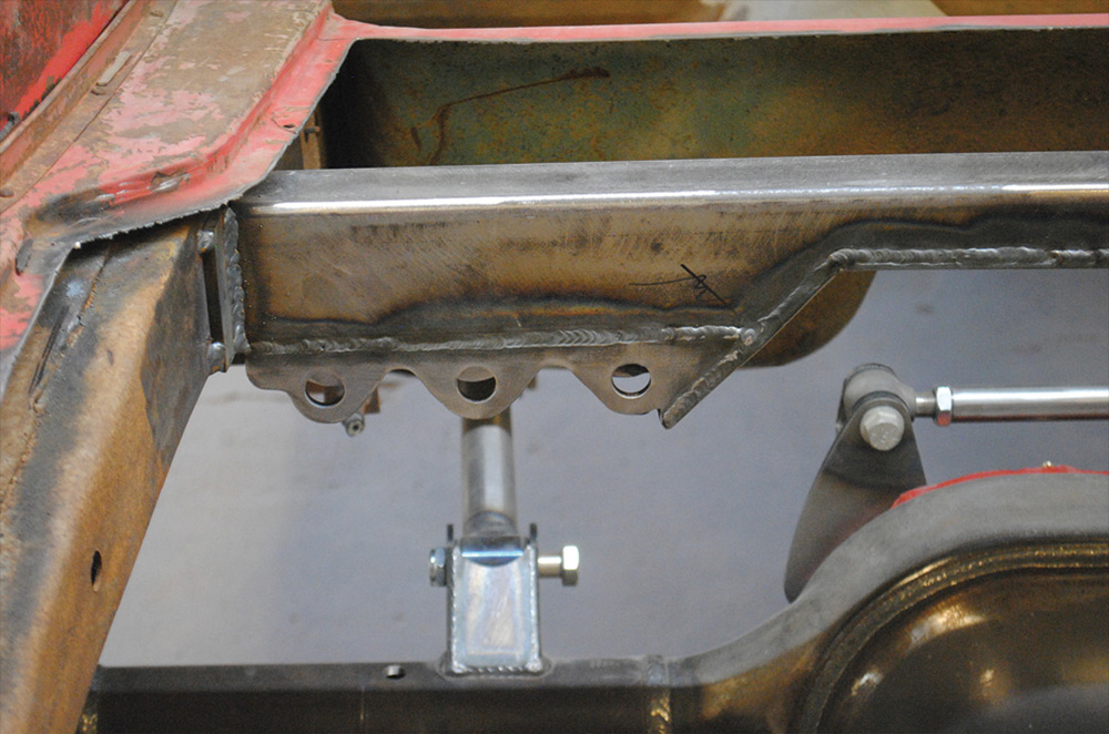
When changing the rear suspension from leaf springs to coilovers, some sort of axle locating system is required. Four-bars and four-links position the axle housing in the chassis front to rear. Four-bars are normally parallel and have fixed mounting points (threaded ends allow minor adjustments for wheelbase and pinion angle adjustments) while four-links allow the attachment points of the links to be altered to tune the chassis. Four-links are most commonly used in drag racing to alter how the vehicle launches from the starting line.
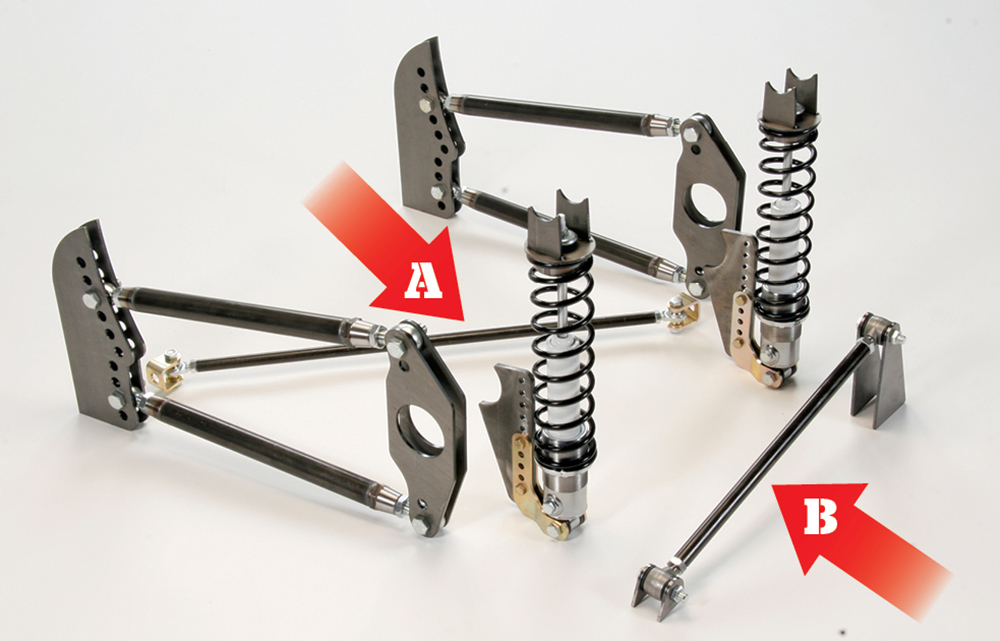
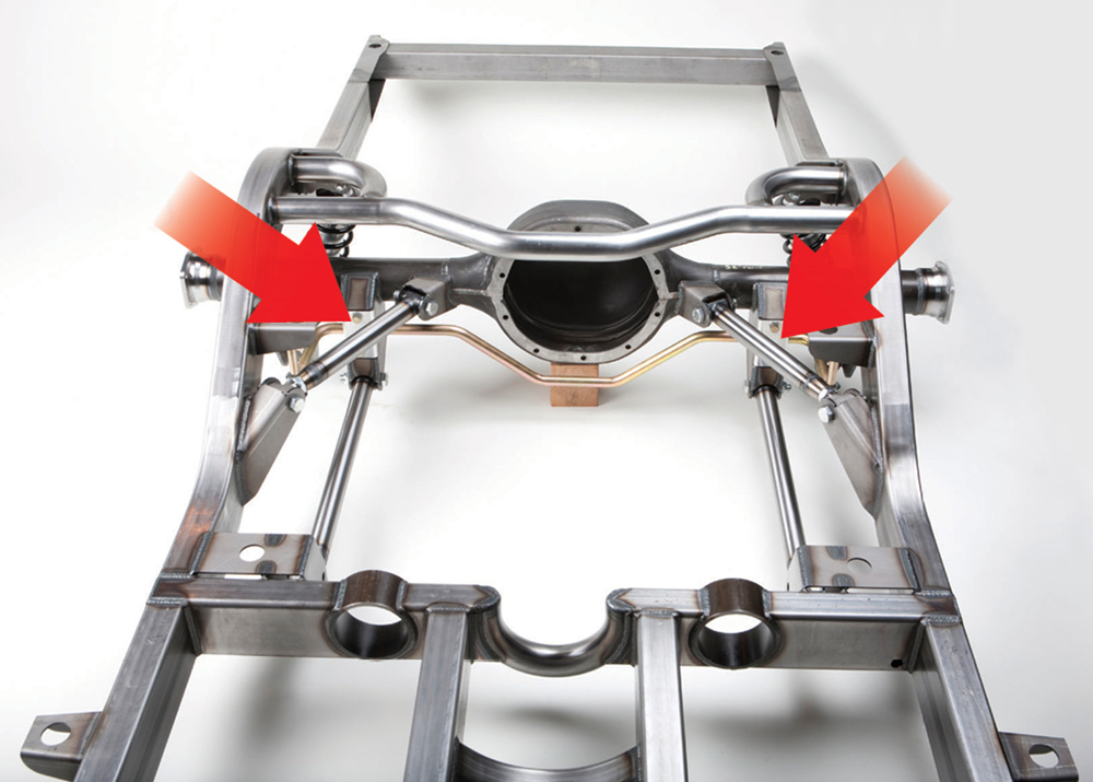
To control sideways movements four-bars and four-links require a lateral locator, such as a Panhard bar or a Watts link. Diagonal locators may also be used, however they are more suited to drag race applications than the street. A variation on the four-bar theme is a triangulated four-bar. Two-bars run parallel with the framerails with two additional bars running at an angle from the axle housing to the frame that locate the housing side to side, eliminating the need for an additional link. Colin elected to use Art Morrison four-bars with a Panhard bar.
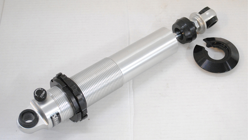
There are a variety of advantages to using coilovers, not the least of which is they are compact by virtue of combining the shock absorbers and springs. But arguably their biggest benefit is the ability to tune the suspension by simply changing springs, mounting angles, or in the case of adjustable shocks the compression and rebound rates. Simple and effective, coilovers are the best kind of shock therapy.
(208) 745-1350
VOLUME 4 • ISSUE 31 • 2023