Modern Rodding tech icon
It’s as simple as hot & cold
Installing Heat, Cool, and Defrost in Your Street Rod
By Brian Brennan | Photography by John Winter
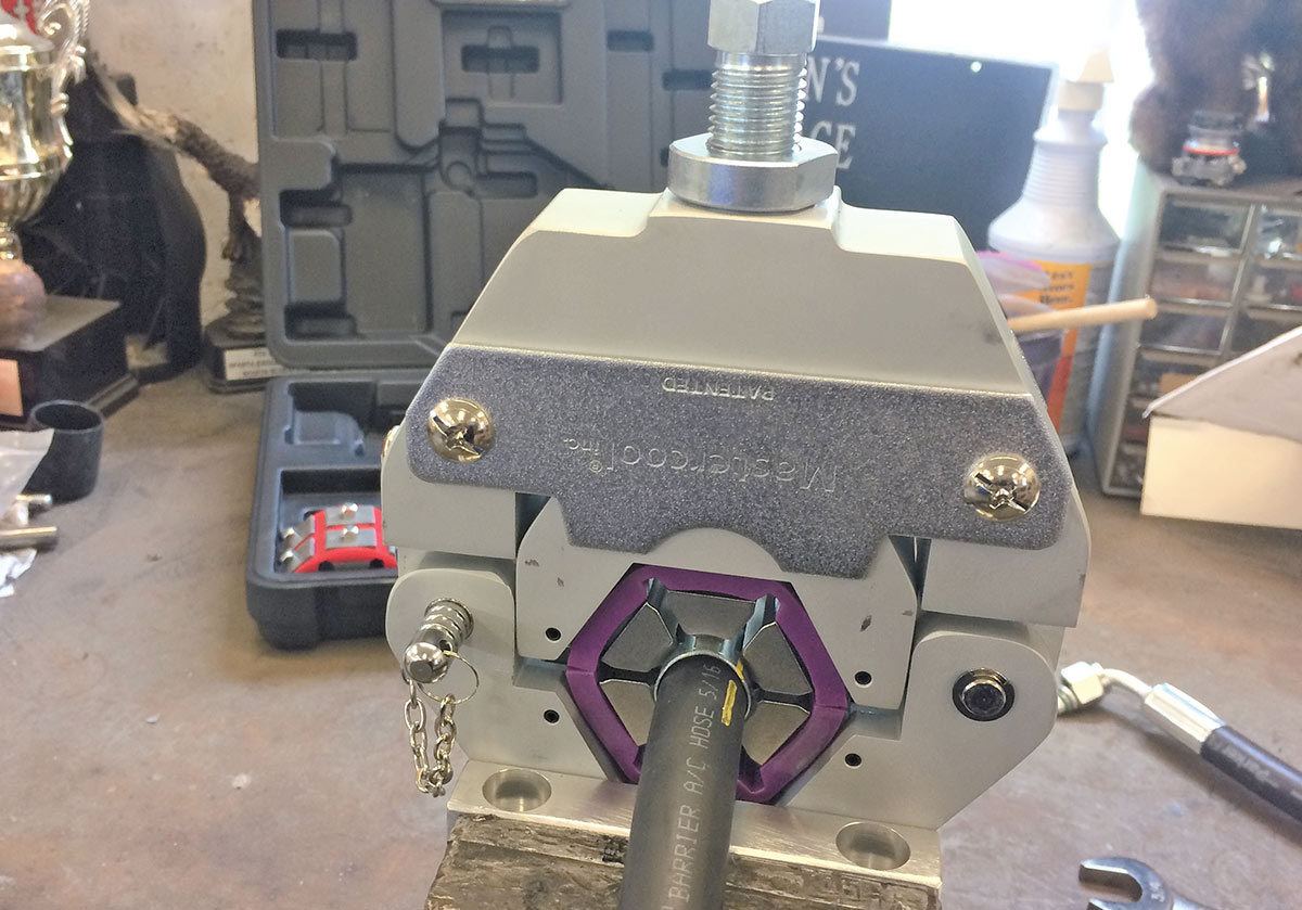
01 John Winter using the Vintage Air (VA) beadlock tool (use and return) to make his high-pressure line crimps for the A/C system.

T

here’s one distinct advantage to any enclosed street rod: you are in charge of the weather, sort of. Truthfully, a closed car with a cool, heat, and defrost system is something we take for granted on our everyday drivers but it’s something we have to engineer into our hot rods.

It was back in 1976 when I first became aware of aftermarket A/C kits for hot rods. I was sweating my way through the NSRA Nats in Tulsa, Oklahoma, when I happened upon Jack Chisenhall with his card table covered in A/C parts. He proceeded to tell me these would fit any number of hot rods, giving rodders something akin to control over heat and humidity. All of us at one point have experienced summer humidity and heat and we truly understand how stifling it can be. A little A/C goes a long way toward maintaining our mindset of “having fun with cars.” A big “thank you” to Vintage Air (VA) for initiating the A/C portion of our industry some 46 years ago.

When it comes time to keep cool or, dare I say, stay warm inside our street rod, there’s a proven method. While this story has some of the goodies on installing an A/C system, we will spend time looking at the louvers (vents/registers as they’re sometimes called) that direct the airflow to make you more comfortable. In today’s world of street rods, it’s commonplace and no longer an afterthought that cars are now built with a heat, cool, and defrost system; we rodders shorten it up by saying the A/C.

For our story we linked up with fellow hot rodder John Winter out of Illinois who just happened to be in the midst of building his 1936 Ford Tudor trunk back sedan. As luck would have it, Winter (you can’t make this stuff up … an air conditioning story with someone named Winter) was in the midst of installing his VA Gen II ComPac (PN 68000-VUZ-A) system. According to VA it uses their Gen II servo motor control technology, which permits this midsized package to perform the work of a larger system. The Gen II ComPac is ideally suited for coupes, classic trucks, and smaller sedans … right in the wheelhouse for the 1936 Ford sedan we are using as our project model. It comes with three outlet vents, allowing you to position your louvers wherever you might need them. It should be noted that VA refers to this system as a “heat/cool/defrost” since it doesn’t incorporate fresh air. The system uses recirculated air from inside the car—basically always in “max cool” configuration. Let’s take a closer look at how Winter handled the louvers and hoses.

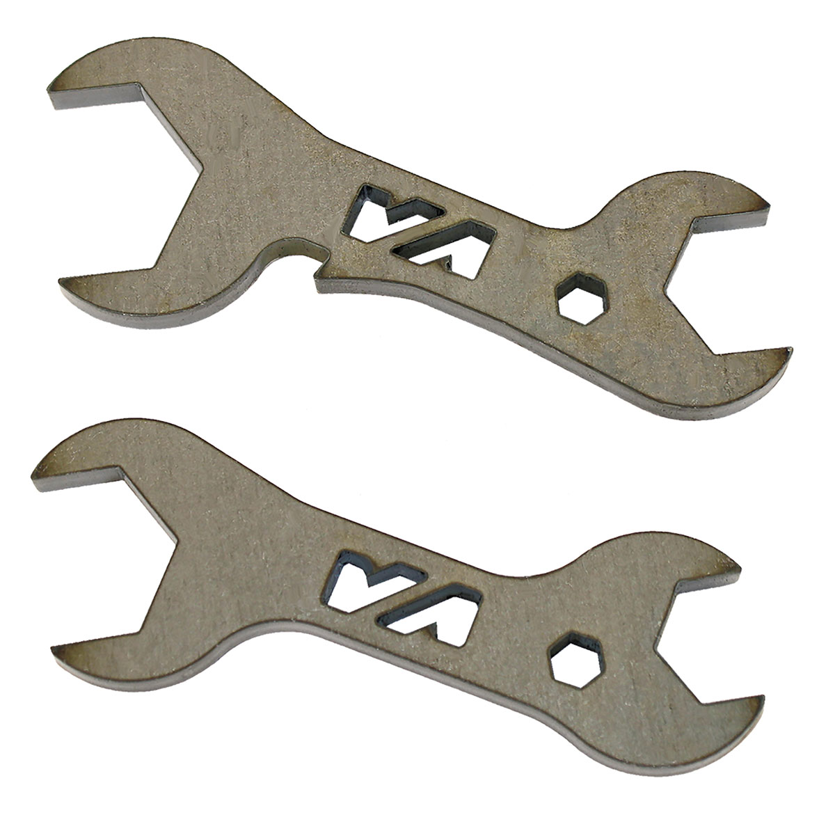
As with any project, tools are an important component. There are several items that we obtained through VA that help make all the difference during the installation. VA offers several handy wrenches you can purchase to assist. They come in two sizes (1/16 x 3/4 inch, PN 646917; 7/8 x 5/8 inch, PN 646918) and are made from non-hardened, laser-cut 1/4-inch steel with a very user-friendly price of $5 each. A perfect match for the line fittings provided in the VA kit. Another time-saving, and in the long run money-saving, tool is the high-pressure line beadlock crimper. We have seen A/C high-pressure lines crimped in various manners but because of the A/C high-pressure line failure isn’t an option. Begin by mounting the beadlock crimping tool to your bench vise. (For those of you who have gotten this far into the article, write myself or Ron Ceridono an email and we will tell you a pretty funny story on how I taught Ceridono how to use a bench vise!) Once you have completed making the proper high-pressure line crimps you can then return the tool (0VA wishes to keep the tool on two-week turnaround) to VA for a refund (use and return) of your deposit.

Other VA components included in this installation are the Gen II ComPac evaporator (PN 55288-VUE-A) and the vertical flow condenser, which on this 1936 Ford would measure 20-3/4 inches tall x 14 inches wide. Additionally, the aluminum hard lines that route to the backside of the radiator are PN 03032-OFV. Also supplied are sections of 2- and 2-1/2-inch duct hose. There’s also the VA drier and trinary switch. Remember, if you are using a mechanical fan for engine cooling then you will most likely be using a binary switch. But should you be using a single- or dual-electric fan for engine cooling then you will be using a trinary switch. The binary safety switch provides high- and low-pressure protection for the compressor (will not allow the compressor clutch to engage if system pressure is below 30 psi, and disengages the compressor clutch if system pressure builds above 408 psi), and the trinary switch provides those same two functions with an additional fan engagement signal (at 254 psi) for the electric fan. Two styles of louvers (vents/registers) were used in this project. The billet aluminum defrost grille trim can be found under PN 63100-UVQ while the injected molded plastic vents used (adjust side to side as well as up and down) are PN 49057-VUL.

As an aside, we also went to several builders (Hot Rods by Dean and Precision Hot Rods) to get some idea on how they handle similar VA louvers. Both companies offer custom applications that rodders can use on their hot rods of various makes and years.

Now, let us follow along and see how Old Man Winter (I am going to hear about that) handled the installation of his cool/heat/defrost louvers and the mounting of his evaporator. The series of photos will show you how he took the stock dash and mounted the aluminum defroster grille as well as the vertical (can be mounted horizontally) injected plastic louvers.
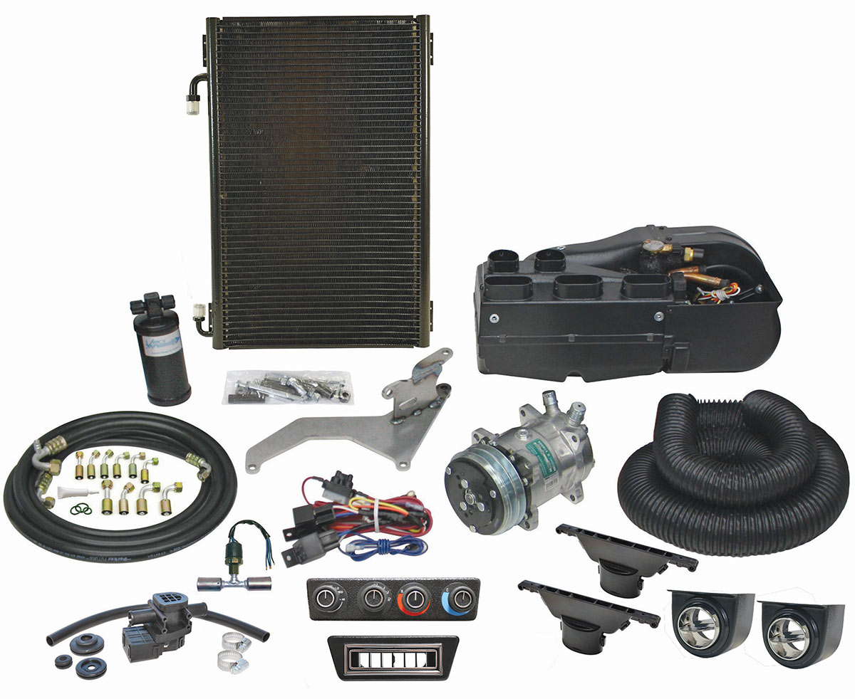
Looking at the VA Gen II ComPac
02 The VA Gen II ComPac (PN 68000-VUZ-A) system is ideally suited for coupes. Should you have a four-door sedan or larger vehicle there are systems intended for these demands.
Looking at the The VA wrench
03 The VA wrench (1/16 x 3/4 inch, PN 646917; 7/8 x 5/8 inch, PN 646918; $5 apiece) is made from non-hardened steel. It is intended for A/C installation and removal of lines.
Positioning the billet defrost grilles
04 Look closely and you will see how Winter positioned his billet defrost grilles with a dash bias to the driver side, thereby making sure there’s plenty of defrost effort on the windshield directly in his line of sight.
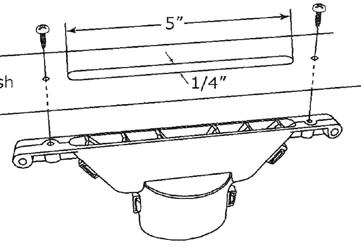
Diagram showing mounting option
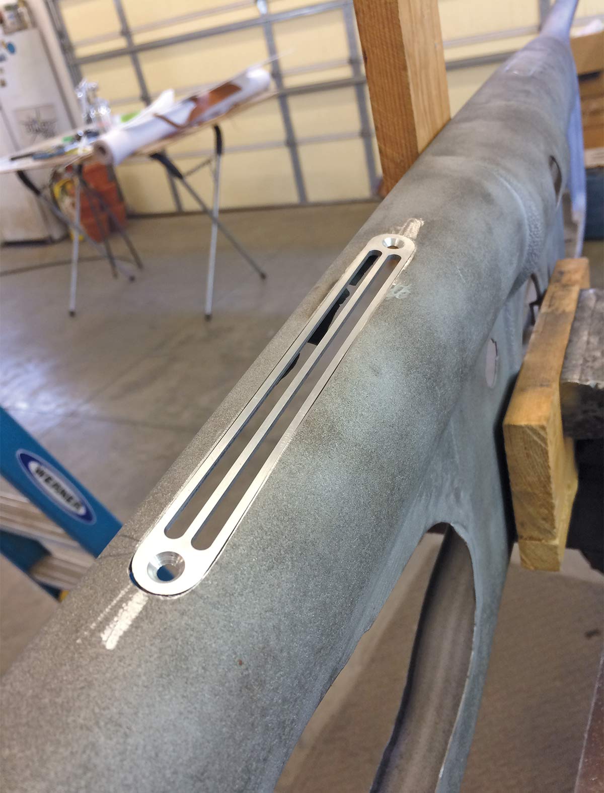
05 Should you wish to mount your defrost grilles on top of the dash they can be positioned so that simple hardware will hold them to the defrost duct. In our case we wanted a flush-mounted grille necessitating minor sheetmetal work.
Installing the billet defrost grilles
A closer look at the billet defrost grilles
Sheetmetal blade product
Sheetmetal blade installation
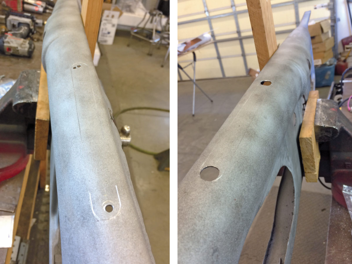
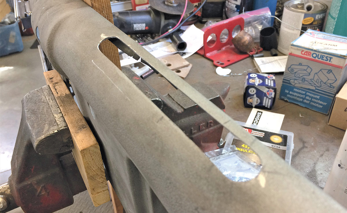
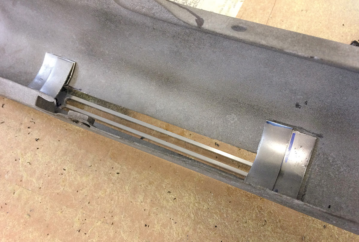
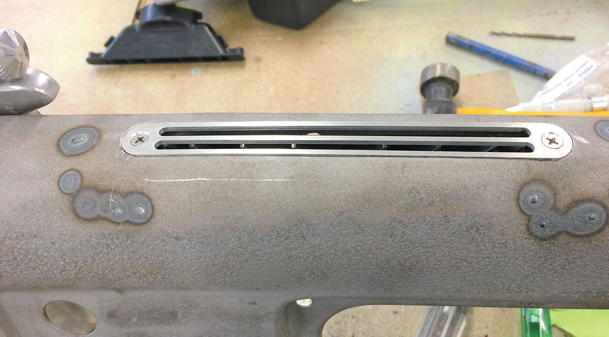
06, 07, 08, 09, 10 The billet defrost grilles (PN 63100-UVQ) are installed in the upper portion of the dash; positioning is up to you. Note the location is marked, pilot holes drilled, then larger holes to allow your sheetmetal blade to be inserted, cutting away excess material. Defrost grilles drop into position and will be held in place via the small brackets that Winter made hidden beneath the dash sheetmetal.
Two cutouts in the sheet metal
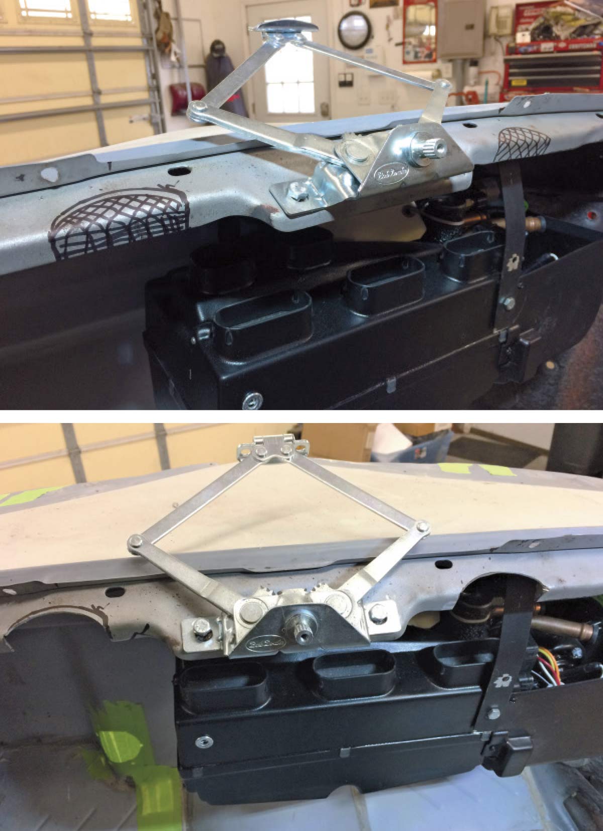
11, 12 Although the Bob Drake windshield crank is visible, we want to draw your attention to the two cutouts made in the sheetmetal that will allow clearance for the defrost ducts to direct air up and through the ducting beneath the defrost grilles.
Looking at the defrost grille
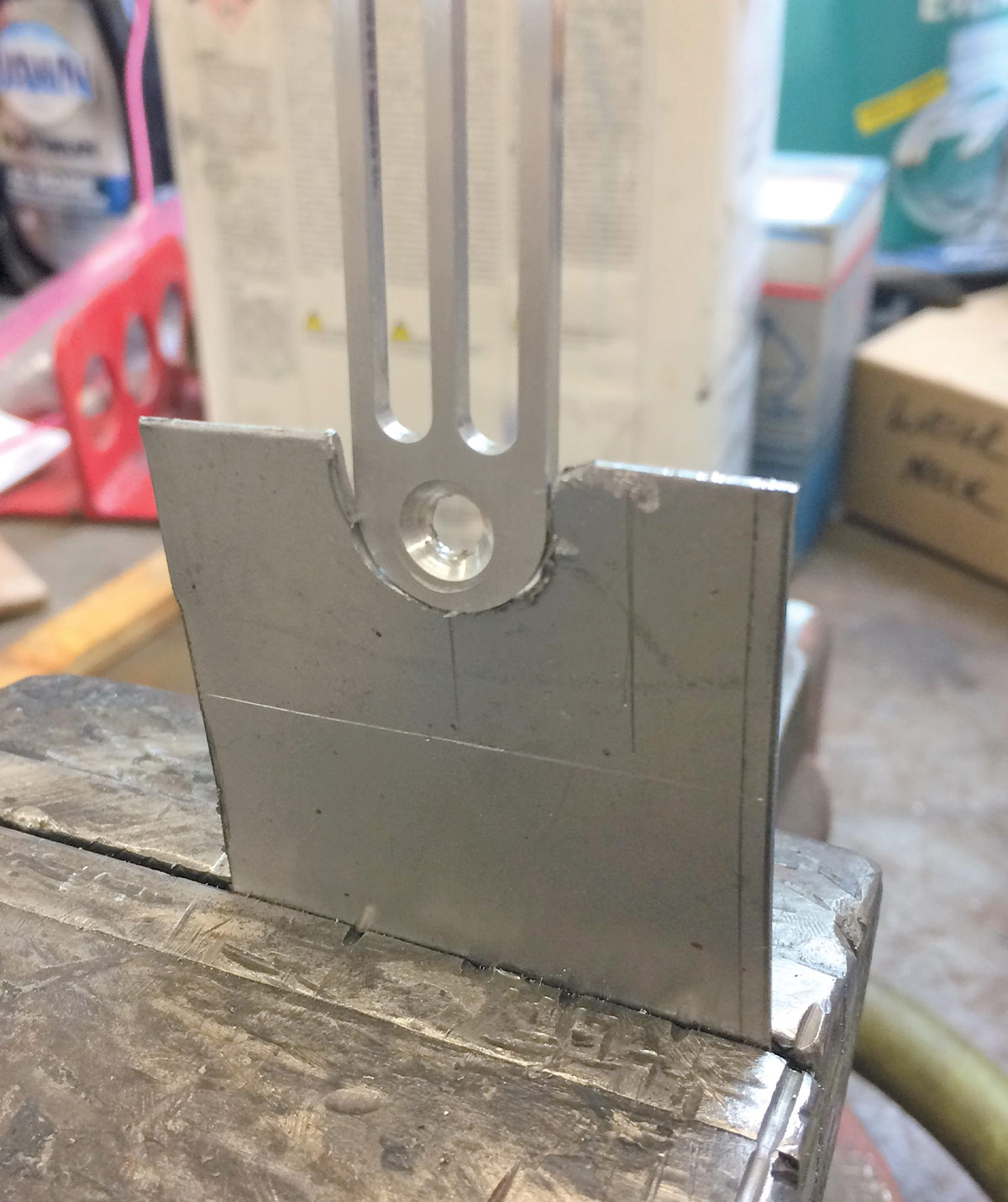
13 The defrost grille is positioned into the sheetmetal and you can see how much metal needs to be removed (notched) from the parent metal.
The cutout portion
The cutout portion
14 The cutout portion on the sheetmetal allows for the billet aluminum defrost grille (PN 63100-UVQ) to fit into position.
Closeup of small brackets
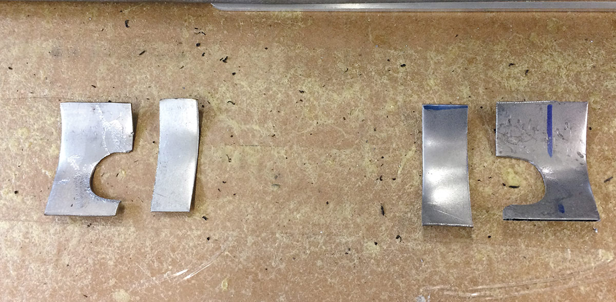
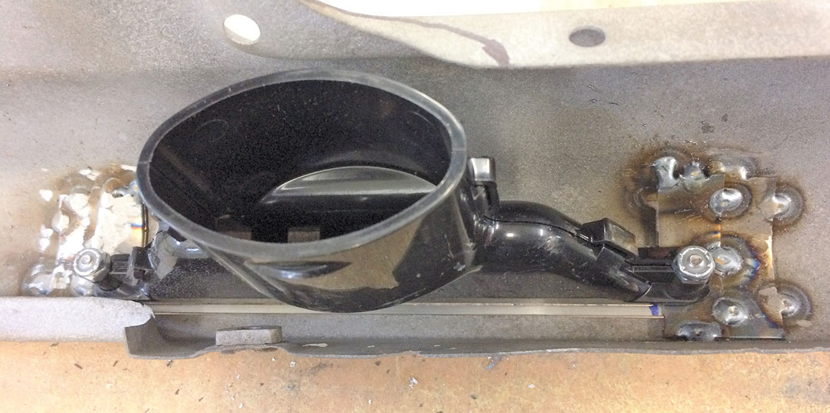
15 Winter made these small brackets and then shaped them to follow the contour of the dash. They hold the universal defroster duct once in position.
Looking at the VA universal defroster duct kit
16 The VA universal defroster duct kit (PN 633910-VUA) is bolted into position with hardware provided; 1/4×20 with Nyloc nuts.
The vents are screwed into position
17 The defroster vents are screwed into position. Note the spot weld heat marks showing where the small brackets are positioned on the backside.
Using VA injected-molded plastic vents
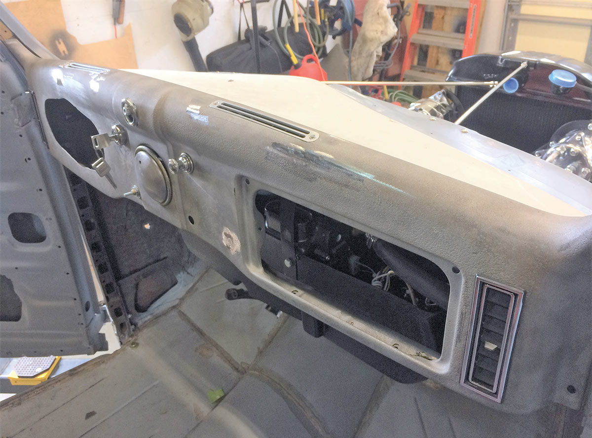
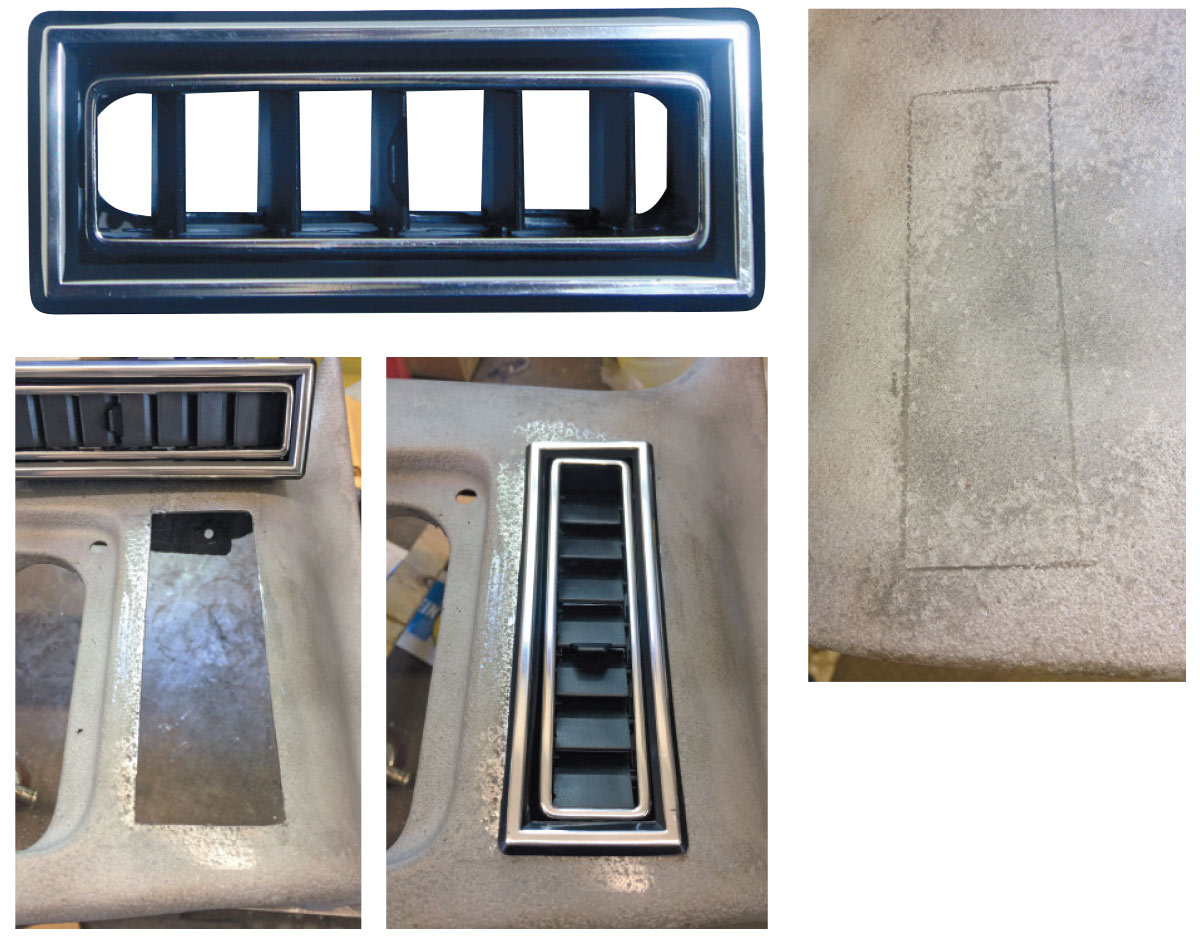
18, 19, 20, 21 The VA injected-molded plastic vents (PN 49057-VUL) can be used vertically or horizontally. Here we show how the dashboard is scribed for proposed cutout, the material removed, and then the vents placed into position. The vents are adjustable left to right and up and down.
The 1936 Ford dash with louvers
22 The 1936 Ford dash with the outer edge vertical louvers in place. Note the gauge panel area is already cut to accept the Dakota Digital instrumentation.
Looking at the use and return beadlock crimper
23 The use and return beadlock crimper from VA mounts to your bench vise. Proceed from here and produce proper high-pressure crimps.
Bulkhead fittings
Bulkhead fittings
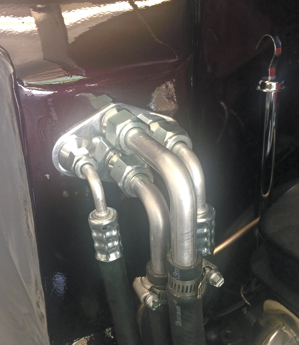
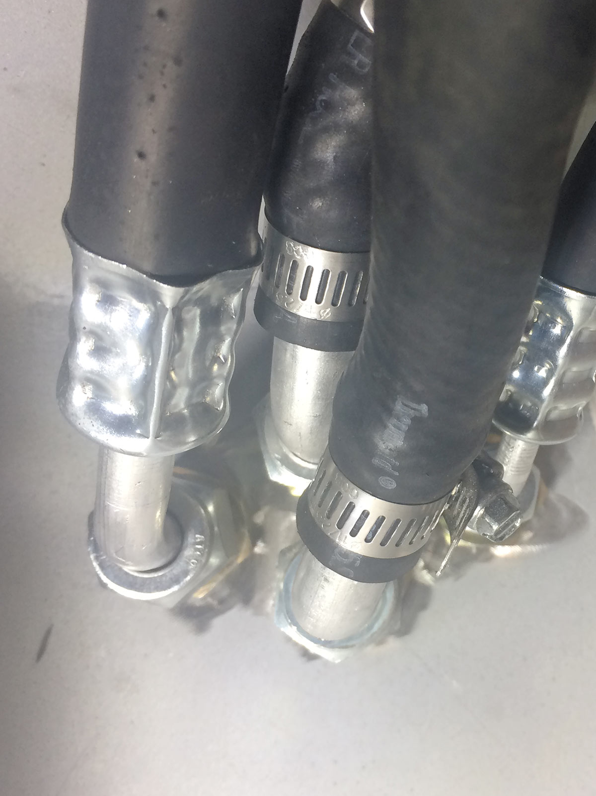
24 Bulkhead fittings at the firewall viewed from the engine compartment. Note the beadlock crimps on the two outer high-pressure lines while the stacked inner water hoses are low pressure with traditional hose clamps.
Illustration shows you the correct way to use the VA wrenches
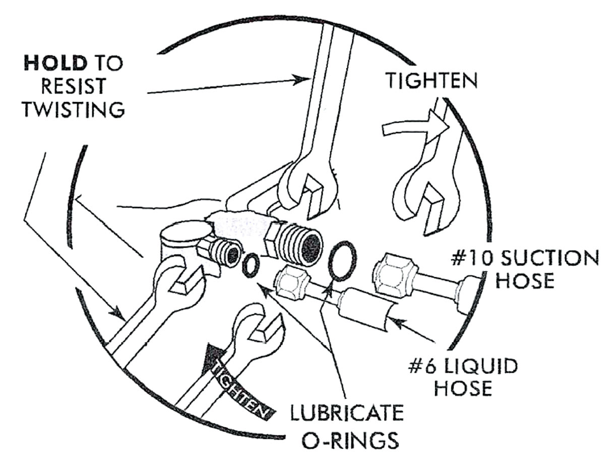
25 This illustration shows you the correct way to use the VA wrenches (1/16 x 3/4 inch, PN 646917; 7/8 x 5/8 inch, PN 646918; $5 apiece). Note, you hold one wrench to resist twisting while the second wrench is used for tightening (or untightening). Also, remember to always check the rubber O-rings, making sure they’re the proper style and aren’t damaged.
Looking at the condenser
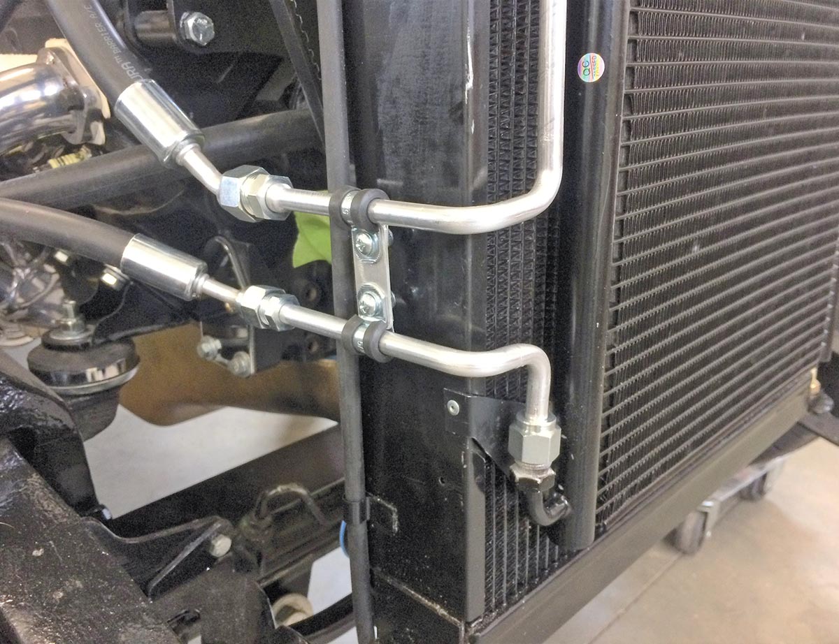
26 The condenser is mounted to the front side of the radiator. Hoses and fittings are part of the VA kit. Winter made up the line clamp that gives both lines additional mounting point and secureness.
VA-provided rear evaporator bracket
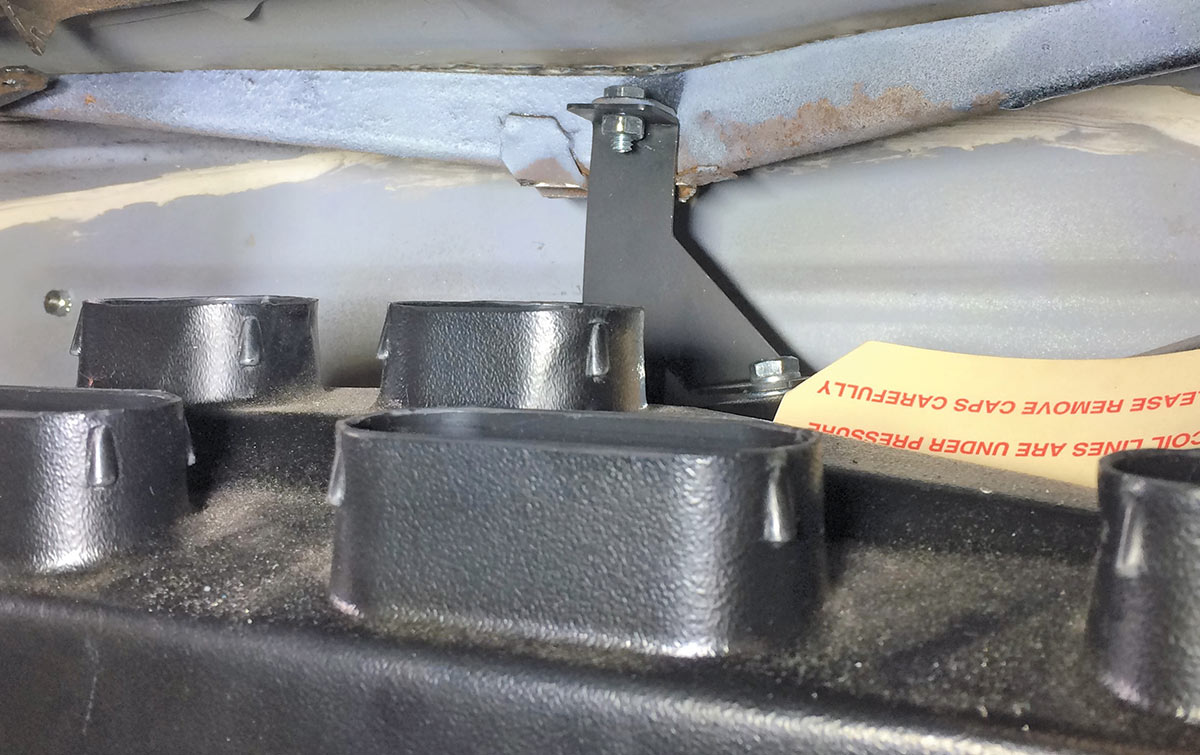
27 Ol’ Man Winter got lucky (and should you have a 1936 Ford so will you) with the VA-provided rear evaporator bracket. The original cowl vent push rod was removed and there was a Ford factory bracket, hole, and all was ready to be used.
The A/C unit is mounted
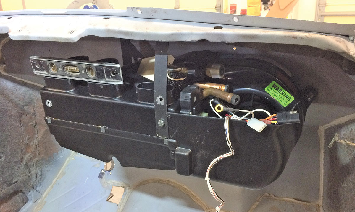
28 The A/C unit is mounted but pay attention to the level (left of picture). Since there’s a condensation drain, we want the unit level so that it drains properly; take into account car rake or lack thereof.
Showing the bulkhead lines
29 Shown here are the bulkhead lines as they pass though the firewall from the interior. Note the outer and innermost lines are high pressure and feature the beadlock crimps. The two stacked inner lines are non high-pressure water lines and affixed with traditional line clamps.
Looking at the rear and front line
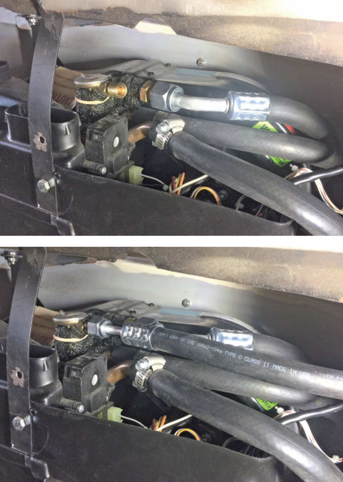
30, 31 The rear line is the high-pressure suction line while the front line is the liquid line from the condenser into the dryer and then into the evaporator (shown). Pay attention to the beadlock tool crimps as they’re distinctive. If your crimps do not look like this make sure they’re the proper high-pressure line crimp and not another form of hydraulic line crimp incapable of handling the A/C pressure.
Where to mount AC dryer
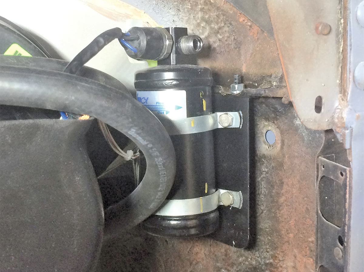
32 Oftentimes we see the A/C drier mounted in the engine compartment but nothing says you can’t mount it inside. Wherever you choose make sure it’s vertical with the switch and hard line end in the “up” position. Do not mount the drier on its side or upside down. Here a trinary (four wires) switch is used, meaning this application will have an electric fan for engine cooling.
Looking at the water control valve and its electrical hookup
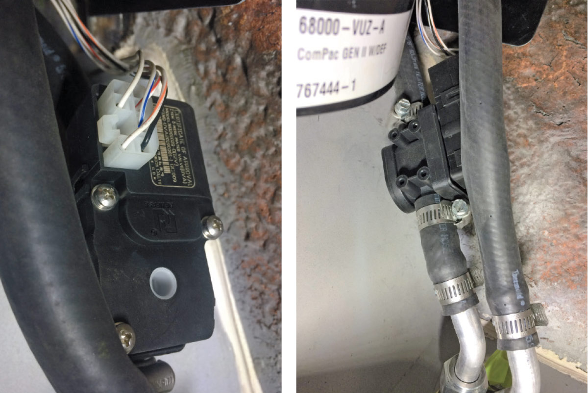
33, 34 You are looking at the water control valve and its electrical hookup that handles the flow providing hot water for the heater and shuts off the hot water so that A/C will function.
The Precision Hot Rods underdash panel
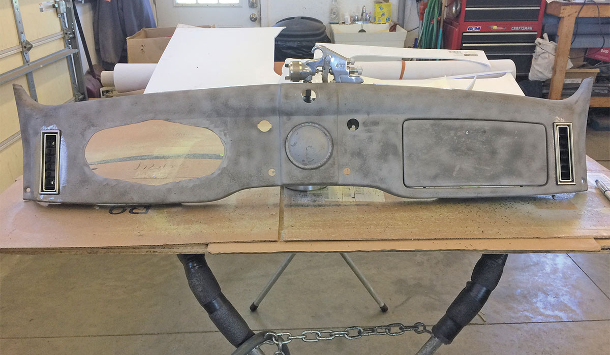
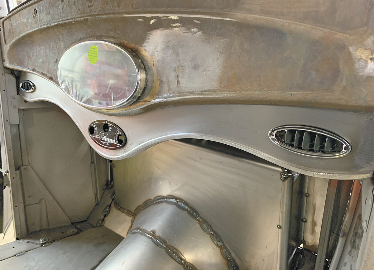
35 The Precision Hot Rods underdash panel follows the contour of the dash shape and easily houses the A/C hardware. You can also use this area for additional switches…
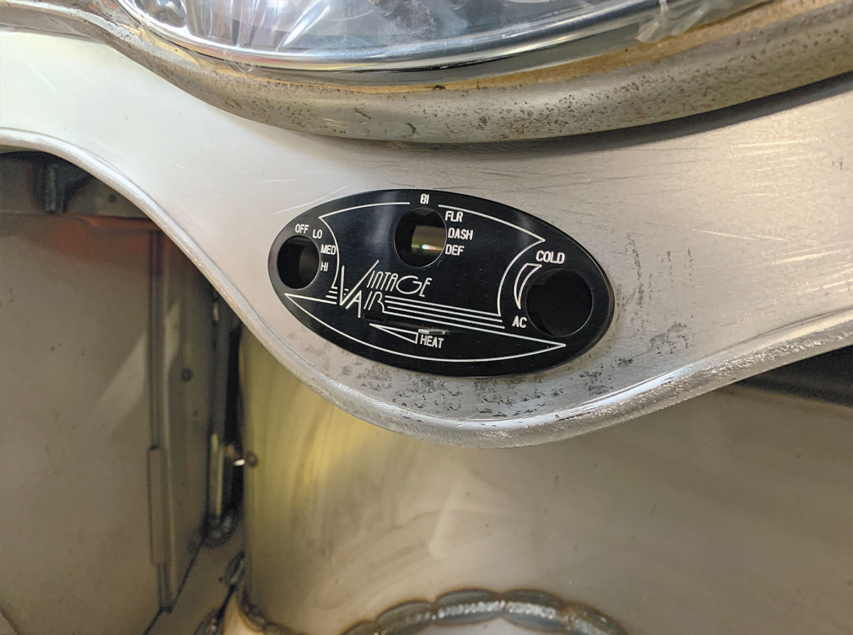
The oval VA control panel
36 The oval VA control panel used here matches well with the oval louvers used at the outside edges of the this underdash panel fabricated by Precision Hot Rods.
Looking at an oval louver
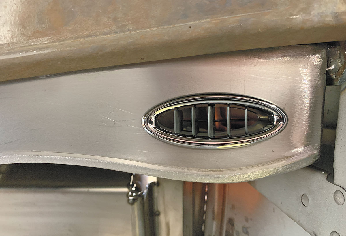
37 Precision Hot Rods uses the oval louver in this application within the underdash panel they offer.
underdash panel for 1942-1948 Fords
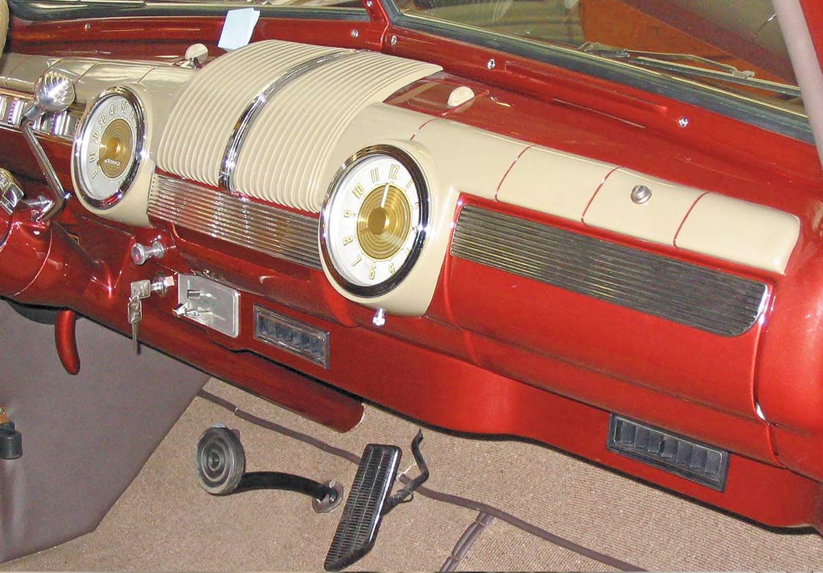
38 The Hot Rods by Dean underdash panel for 1942-1948 Fords takes over the duties of the ignition switch, VA control panel, and a trio of louvers (one isn’t visible but it’s to the left of the steering column).
Underdash panel for 1940 Fords
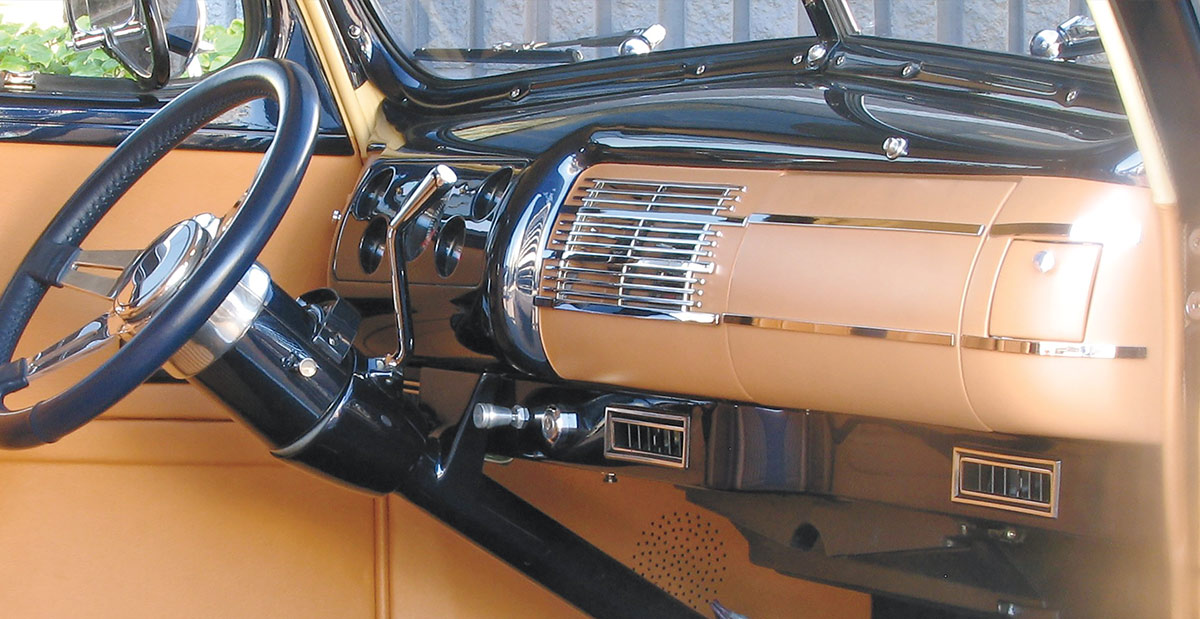
39 Hot Rods by Dean offers this underdash panel for 1940 Fords, shown here handling the chores of ignition key, headlight switch, and louvers for heat/cool.
Looking at underdash panel (1932 Fords)
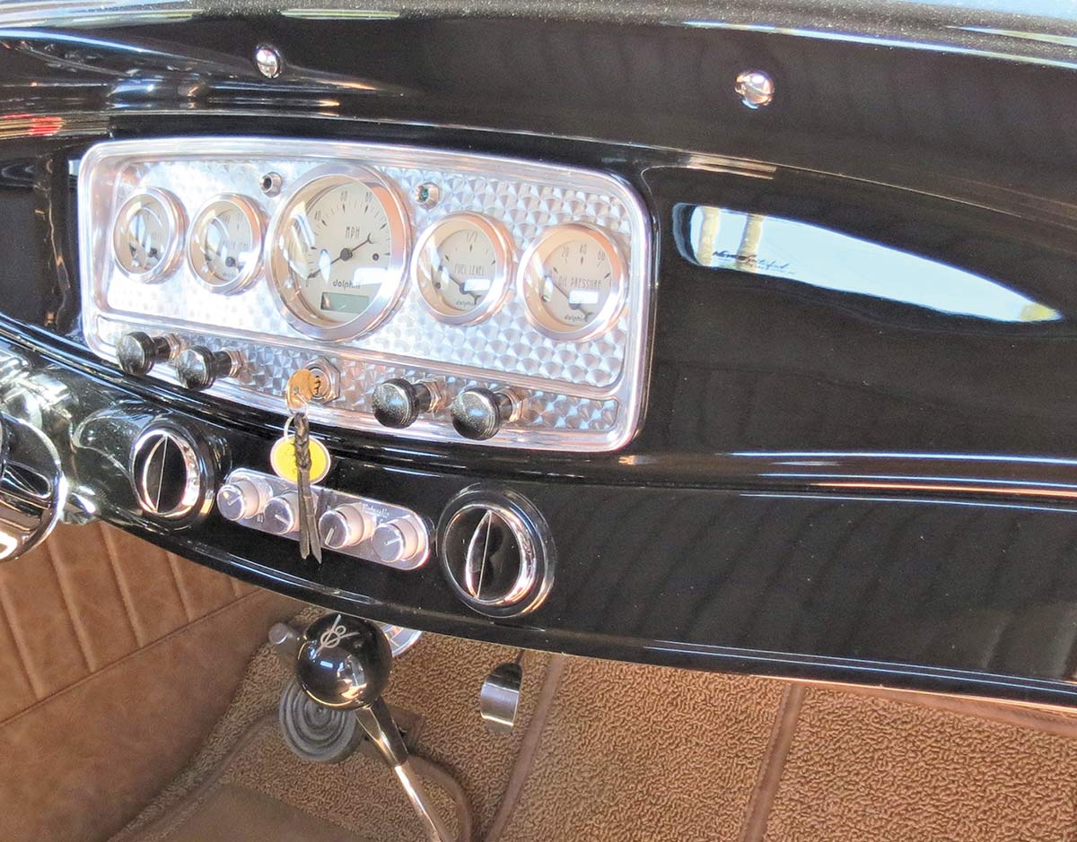
40 Again, available from Hot Rods by Dean is this underdash panel (1932 Fords) that utilizes VA louvers and serves as a home for controls and other switches.
Sources

Vintage Air
(800) 862-6658
www.vintageair.com

Hot Rods by Dean
(800) 362-9709
www.hotrodsbydean.com

Precision Hot Rods & Fabrication Inc.
(330) 908-0234
www.precisionhotrodsandfab.com

Modern Rodding | September/October 2020