Modern Rodding TECH

InTheGarageMedia.com

The Climes They are a-Changin’ title
Time Made the ’82-88 Monte Carlo and El Camino Cool.
Vintage Air Made Them a Whole Lot Cooler.
By Chris Shelton
I

’ll admit, it seems a little odd to replace the factory climate-control system in an ’82-88 Chevrolet Monte Carlo or El Camino with anything else. After all, these were cars built by a corporation that owned Frigidaire, a manufacturer so renowned for refrigerators that some cultures still refer to refrigerators in general as Frigidaire. But there are reasons. Hear us out.

As good as they are, GM’s systems aren’t without shortcomings. First off, they were designed to use R12. Yes, R12 is still available, but good luck getting any without a license. Sure, a system designed for R12 can be converted to operate on its replacement, R134a, however, it requires replacing every O-ring with compatible material, gambling that the old non-barrier hose won’t sweat refrigerant, replacing damaged or sweating old hose with new barrier hose, replacing the filter/dryer, flushing the system—including the compressor—filling the compressor with compatible oil, installing R134a adapter ports, and, in some cases, replacing the old tube-and-fin condenser with a more efficient parallel flow design—and that assumes everything from the original system remains and functions properly, which is unlikely after 40 years; less likely if the car sat for any period. Maybe a prior owner removed and lost critical components when the system stopped working. Or maybe in their haste they damaged or cut those critical components when the fittings that connected their hoses wouldn’t break free easily. Or maybe just all that plastic in the system finally had enough heat cycles and started to decompose. And let me tell you, it seems that cars from this era were made of nothing but plastic.

If any of the above even remotely describes your ’82-88 Monte Carlo or El Camino, you’re aware of the money required to bring a system like that back to life. Vintage Air knows it, so the company recently expanded its product line to include these cars. And we’re all the better for it.

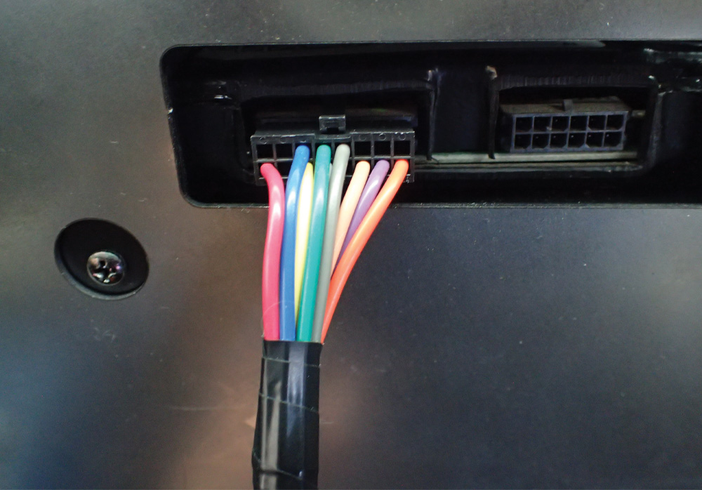
I know it sounds crazy, but we’ve learned a thing or two about climate-control systems since GM built these cars. Because of these technological advances, Vintage Air was able to design a system that performs better than the old Frigidaire systems yet weighs less and takes up less space—it even eliminates the factory air box that clutters the engine compartment. Smooth-operating electronic slide potentiometers mounted in a control panel that mimics the look of the OEM part, compact wires and stepper motors replace the various levers, cables, and manual shutter doors, making operation as effortless and precise as anything you’d find in a modern production car. And the company does it for less than what it costs to repair or restore the existing OEM system.

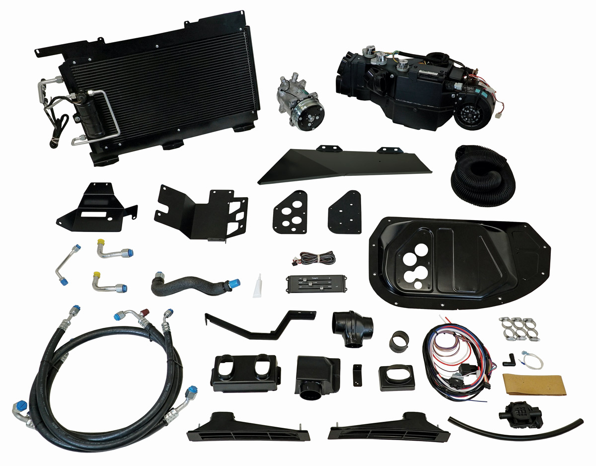
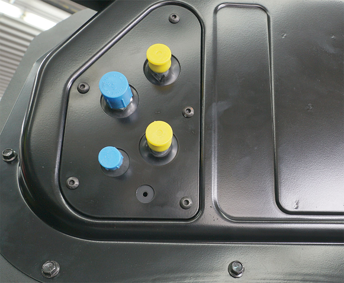
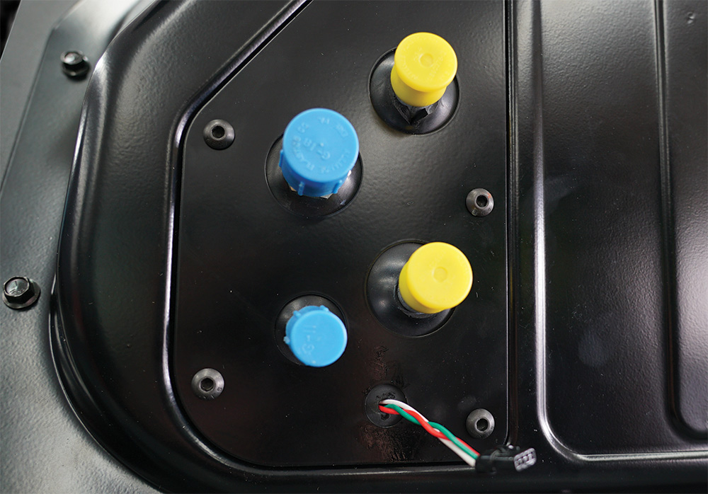
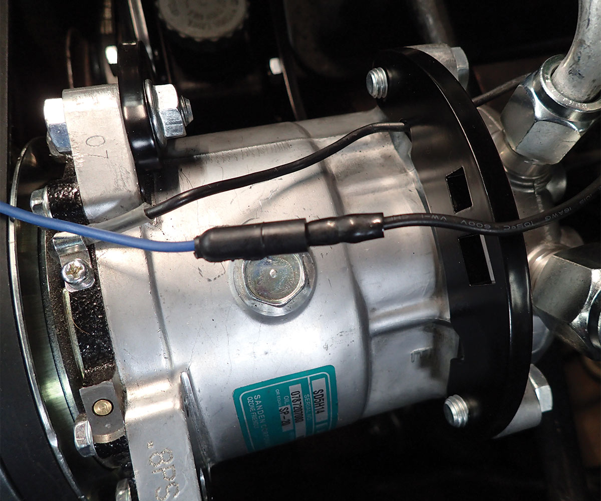
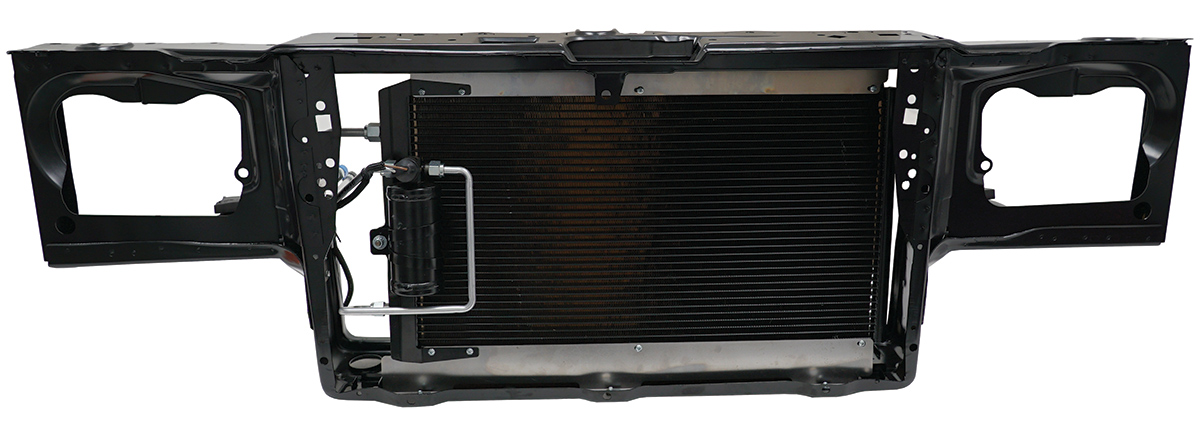
Vintage Air’s SureFit system for ’82-88 Monte Carlos and El Caminos (PN 965083) applies to vehicles that came from the factory with air conditioning. It includes the company’s renowned Gen IV evaporator sub case, the application-specific components necessary to install it, and panels to close the holes left by the old system. This kit includes a Sanden compressor and a parallel flow condenser to replace the antiquated R4 and inefficient tube-and-fin condenser; however, Vintage Air can tweak the kit to accommodate the R4 and has multiple bracket options, including its Front Runner to accommodate LS or LT engine swaps.

These kits use R134a refrigerant exclusively and include filling specifications to take the guesswork out of system charging. Vintage Air supplies the kit with a binary safety switch; however, applications that use electric cooling fans require an optional trinary switch to provide fan engagement with A/C system pressure.

A Word About Clean Power
The pops, clicks, and whines present in a vehicle’s audio system may sound annoying, but they represent a legitimate threat to sensitive electronics in your car, including the ECU in the Vintage Air climate controller. It requires power free from ignition and charging-system interference and a direct path to the battery’s ground terminal.

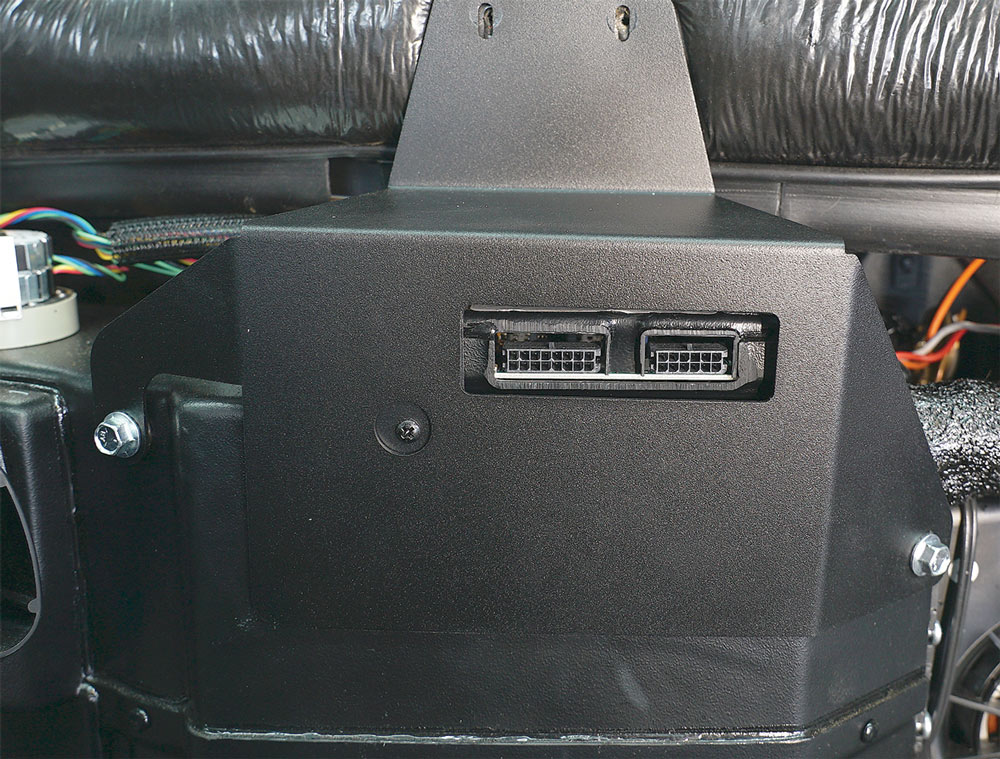
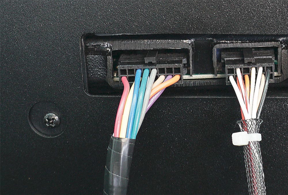
Verify the condition of the battery leads, paying particular attention to the ground side. Ground the block directly to the negative terminal as the manufacturer originally did. Also ensure sufficient ground paths from the climate-controller’s ECU, the blower fan controller, the body, and the chassis to the battery’s negative terminal. Those ground wires needn’t connect directly to the terminal; they can meet at a secondary ground point, like the ground lead on the block, so long as there’s an unobstructed path of copper and terminals from it to the battery’s negative post.

Manufacturers equipped vehicles from this era with capacitors in the ignition’s primary side and by using alternators with internal capacitors to suppress noise. However, well-intentioned prior owners often remove ignition capacitors and alternator remanufacturers can specify inferior parts. If your ignition lacks the capacitor on the primary side, install one. If the audio system still whines with the ignition capacitor in place and grounds sorted, wire an interference capacitor into the alternator’s battery terminal.

Taking these precautions to ensure a good, clean power supply to a vehicle’s electrical components does more than eliminate the pops, clicks, and whines that plague its audio system. They ensure the best possible performance and the longest life for your cool investment.

Take the following as a general overview of what it takes to install a climate-control system. It’s not a definitive step-by-step installation—it took Vintage Air 32 pages to do that, and the results are well worth it (and available for free on the company’s website if you want a finer-resolution rundown). Installation requires somewhat intensive vehicle disassembly. While it’s unfair to call these cars complicated, they’re a lot like onions in the sense that they have many layers and peeling them apart without taking precautions can move one to tears. But the official installation manual covers every step and detail right on down to individual screw locations.

This overview assumes some steps that we don’t cover here. First, responsibly evacuate the existing refrigerant if present in the system. Federal law prohibits those not licensed to service refrigeration systems (that’s almost all of us) to evacuate R12 refrigerant even by the approved methods. Fortunately, licensed repair shops will do it for little charge and in some cases will buy your remaining R12 refrigerant.

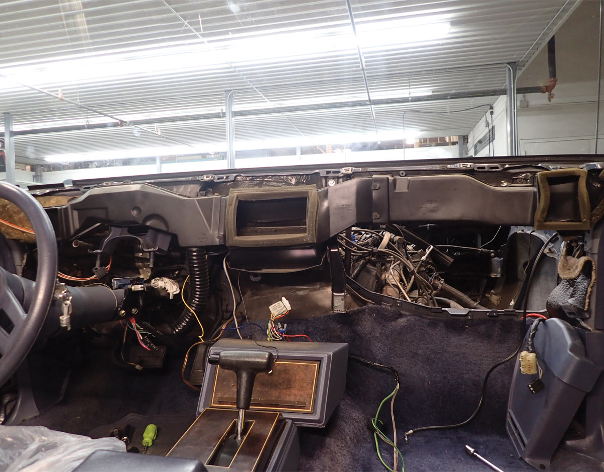
Second, this job requires jacking up your car’s nose and supporting it with stands. Installation requires the removal of numerous components, like the passenger wheel and inner fender and the radiator, all things made easier (or just plain possible) with the car off its front wheels.

Though somewhat involved, installation is straightforward, requires only basic hand tools, and thanks to Vintage Air’s engineering, lends itself to the enthusiast’s skill set. And most of all, Vintage Air takes the risk out of restoring ice-cold air delivery to your Monte Carlo or El Camino. No tears required.

Vintage Air aircon parts
1. The SureFit kit includes everything from the air handler (evaporator), bolt-in condenser assembly with drier and safety switch, a Sanden compressor with mounting kit, and refrigerant hose.
Dismantled G-Body Monte Carlo dashboard
2. We gloss over dash removal because it’s intense and Vintage Air does a good job explaining it. It also requires removal of five screws that hold the factory ducting still intact here.
Evaporator firewall bracket
3. Begin reassembly by installing the evaporator firewall bracket, shown here in place. It mounts under the four 1/4-20 bolts screwed into the evaporator case.
Heater and refrigerant hardlines
4. Install the hardline into the expansion valve (hidden behind the upper heater line) and the upper and lower heater hardlines. Note: Keep the refrigerant-line caps in place whenever possible. Nitrogen in the lines prevents moisture from contaminating the lines.
Evaporator placed in firewall cover
5. Drop the prepped evaporator into the stamped steel firewall cover and bolt everything together. Seal the cover to the firewall with butyl rubber or silicone.
Firewall rubber boot and cover plate with hardline endcaps
6. Install the rubber boot and cover plate, taking extra care to maintain the tightness of the hardlines. To ease installation, spray the boot with soapy water and remove the hardline caps, taking care to reinstall the caps immediately after the boot installation.
Drilled hole for new hose in firewall
7. Drill and ream a hole no bigger than 5/8 inch through the firewall below the opening where the factory climate system is mounted. The hose needn’t be installed at this point; however, drilling the hole at this point is much easier than with the evaporator in place.
Firewall and evaporator assembly mounted
8. Now mount the firewall cover and evaporator assembly into the opening. Seal the bolts with silicone to protect them and the interior from water ingress.
Outside of firewall and evaporator assembly
9. The evaporator mounts to the body in two places: by the firewall cover plate and by this smaller dash bracket. Use the slotted holes as guides to drill the two mounting holes in the upper firewall.
Replacement bracket for OEM dash support brace
10. The evaporator case interferes with the factory dash-support brace so Vintage Air includes a very robust replacement bracket. It ties the upper firewall to the bottom of the dash below the radio using the OEM holes and hardware. Install it loosely at this point.
Heater-control-valve harness wiring prep
11. Start routing wires by pulling the heater-control-valve harness (shown) and roughly 27 inches of the red, white, and blue wires from the main harness through the firewall boot’s bottom hole.
Main wiring harness plugged into evaporator
12. Then plug the main wiring harness into the evaporator.
Dashboard vent hose adapter
13. The kit includes hardware to adapt the universal hose to the various vent locations. This one fits into the dash just left of the instrument cluster. Seal the joint with silicone.
Reducing sleeve for underdash louver housing
14. A simpler reducing sleeve adapts the hose to other vents, like the one for the underdash louver housing. Seal this with silicone as well.
Defrost vents and plenum
15. The defrost grilles and defrost plenum sandwich the dash through the existing defrost vent holes. The 10-24 studs welded to the defrost grilles hold everything together.
Center louver adapter in dash
16. The center-louver adapter mounts behind the woodgrain insert by the factory mounting hardware.
Reinstalled dashboard insert
17. Tighten the various adapters and replace the dash insert. Doing it at this point makes its installation a little easier.
OEM dashboard control panel

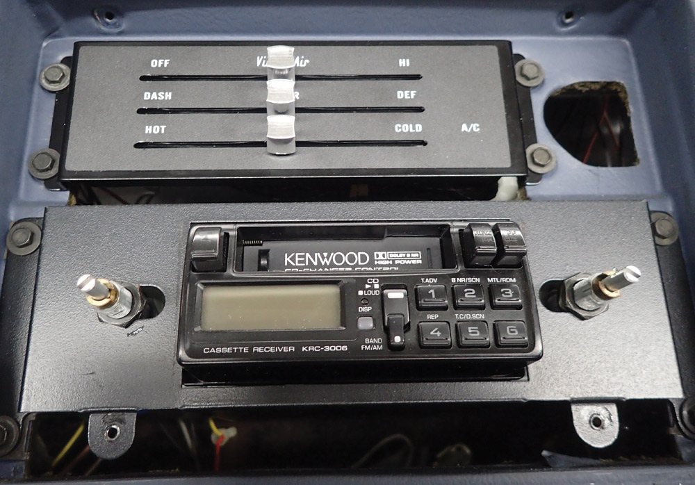
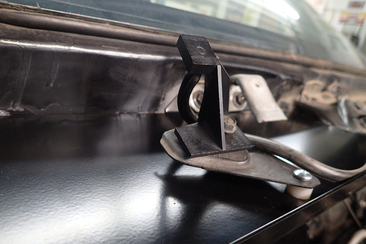
18. The control panel mounts in the factory location using the OEM hardware. Install it now.

Control panel plugged into evaporator ECU
19. Position the dash in the car but before mounting it permanently. Plug the control panel into the open socket on the ECU mounted atop the evaporator.
Evaporator drain line
20. The drain line installation represents the final step in our version of the installation. Technically one could install it after mounting the ECU in the firewall. The choice is yours.
Wired circuit breaker and relay mount
21. The supplied circuit breaker and relay mount to the passenger-side fender just behind the battery. Reattach the terminals but do not reconnect the battery ground terminal yet.
New installed heater-control valve
22. Install the heater-control valve using the supplied hardware. The stepper motor in this valve offers more reliable operation than the OEM vacuum valve.
Sanden mounted to new Vintage Air bracket
23. Vintage Air makes this bracket to mount the quieter, more efficient, more durable Sanden in the factory location. It works with or without the power steering pump.
Trigger wire from safety switch connected to clutch
24. Connect the trigger wire from the safety switch to the clutch and nothing more. Do not run any other components from this wire—use a trinary switch to activate cooling fan relay(s), if necessary. And most of all, never let it short to ground with the system energized.
Parallel flow condenser assembly bolted to core support
25. Plumb the dryer and adapter brackets to the parallel flow condenser and bolt the assembly to the core support. Vintage Air designed it to fit as if the factory made these cars this way.
Hood seal and windshield washer mounting points
26. The factory air housing doubles as the hood-seal mounting point and the windshield-washer mounting point. The water deflector included in this kit serves the same purpose and finishes the installation.
Man evacuating G-Body Monte Carlo aircon system
27. Finally, evacuate the system for 35 to 45 minutes at 85 degrees F or warmer. Use a heat gun or run the engine to bring up the temperature, if necessary. If it holds a vacuum for at least an hour, fill the system with the weight Vintage Air recommends for your combination.
Vintage Air
(800) 862-6658
vintageair.com
Modern Rodding

VOLUME 3 • ISSUE 24 • 2022