 Photography by Rob Fortier Videography Courtesy of Vintage Air
or the longest time air conditioning was a dream that many an early hot rodder didn’t have—in fact, couldn’t have—on their early iron. As times changed air conditioning worked its way onto all forms of transportation to the point it’s almost impossible to purchase any car or truck today that doesn’t have a sophisticated cooling and heating system. Even so, hot rods and A/C were still distant cousins. However, over time Vintage Air (VA), serving the rodding community since the mid ’70s, made it “kool to be cool.”
In fact, Vintage Air founder Jack Chisenhall proved a point back in 1995 by taking his 1953 Studebaker (initially begun at the hands of the late Jim Ewing of Super Bell Axle Company) and stuffed a 705-inch Chevy into it and cranked out a max run of 241 mph. Oh, did we mention that the Stude maintained a constant 40-degree cool air from the VA A/C unit while at speed! VA has gone on to additional eye-opening accomplishments. For instance, back in 2003 Ford Motor Company reintroduced the Ford GT and selected VA to be the A/C unit supplier and they continue to be on the current generation GT. It was 18-plus years ago that VA developed an A/C system for electric vehicles. (Yes, electric hot rods are in our future. —B.B.) Once again, on the leading edge of our industry by supplying what’s needed.
That brings us to an offering from VA: the Heritage Series (A/C and heat) system, which took home 2015 SEMA Best New Product Award and three 2015 Global Media Awards. We asked current VA President Rick Love for some input on why VA came out with the Heritage Series.
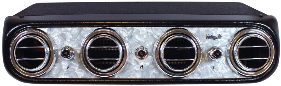
Love told us: “We wanted a system that was a throwback to the ’60s and we already had the MK IV, which was built from the original ’60s tooling, so the introduction of the Heritage Series was a natural. This time we used the round vents, and it also gave us the opportunity to make it a heat as well as a cool system. Also, with the Heritage we were able to use some different bezel trim; Pearl (PN 674011), Engine Turned (PN 674012), Brushed (PN 674013), and Black Turned (PN 674014).”
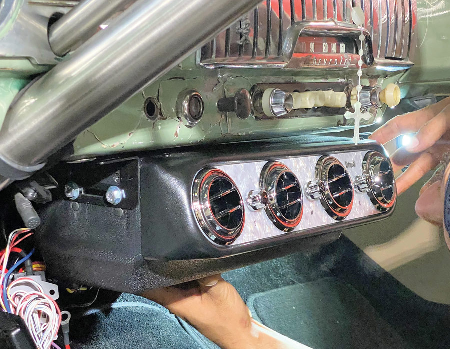
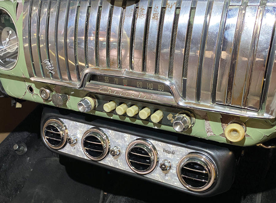
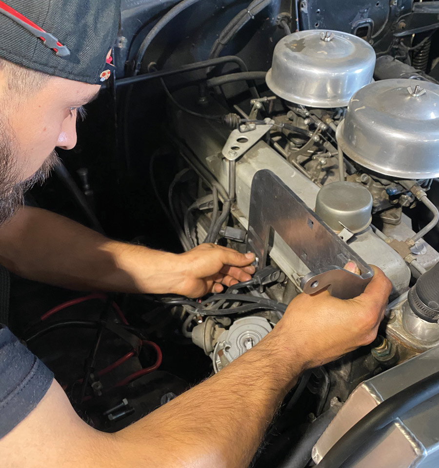
For the story at hand, we feature the Mother of Pearl bezel, which gives those with early ’60s customs a chance to have an A/C and heat system that fits right in with what they are trying to accomplish. And that brings us to the current installation. We stopped by the Jimenez Bros. Air Ride & Rod Shop and spoke with Jobe Jimenez and he showed us an installation on a 1952 Chevy Bel Air with a 292-inch straight-six that was going on at the time. He and Rio, one of the shop’s craftsmen, showed us how the installation went.
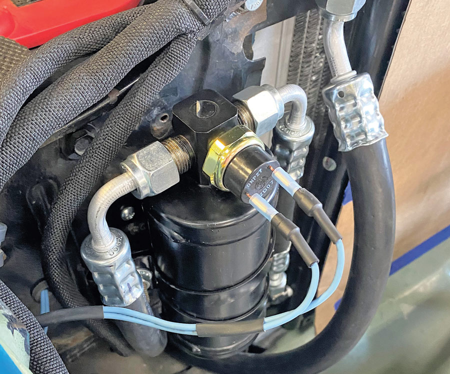
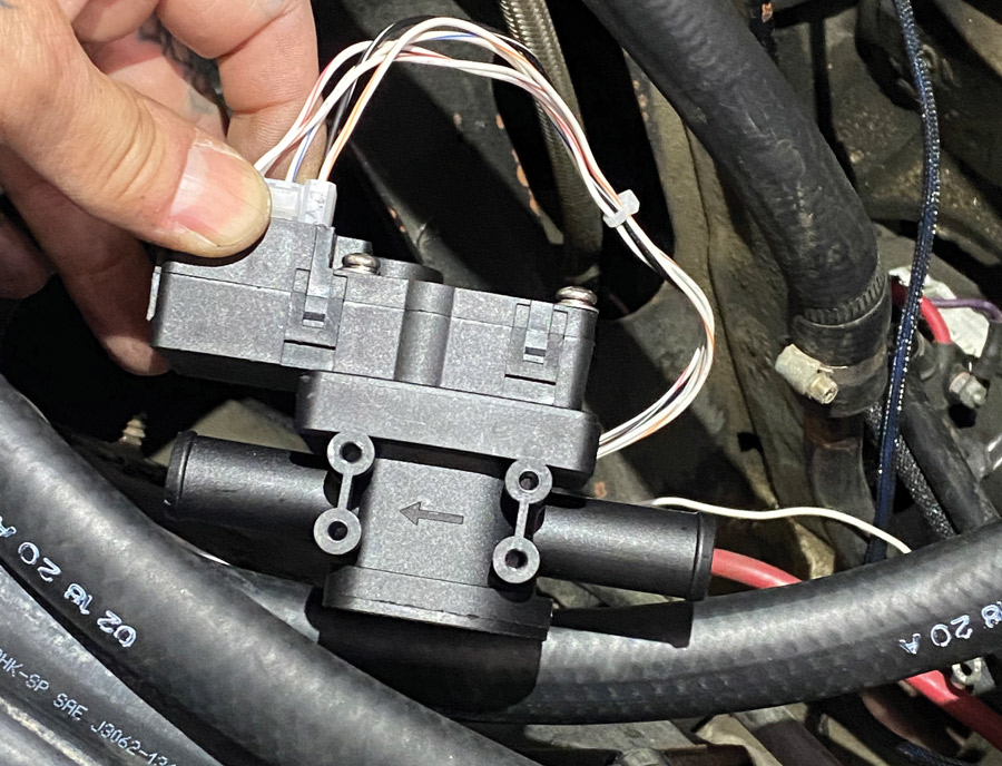
The system comes with a binary pressure safety switch, which is ideal for systems that utilize a mechanical block-mounted cooling fan. Should you find yourself using an electric fan you will want a trinary switch to add a fan engagement signal with A/C pressure. Let VA know your requirements at the time of order and they will make sure you have the proper compressor safety switch.
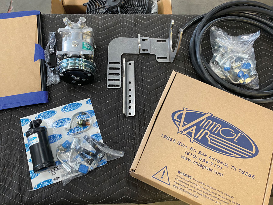
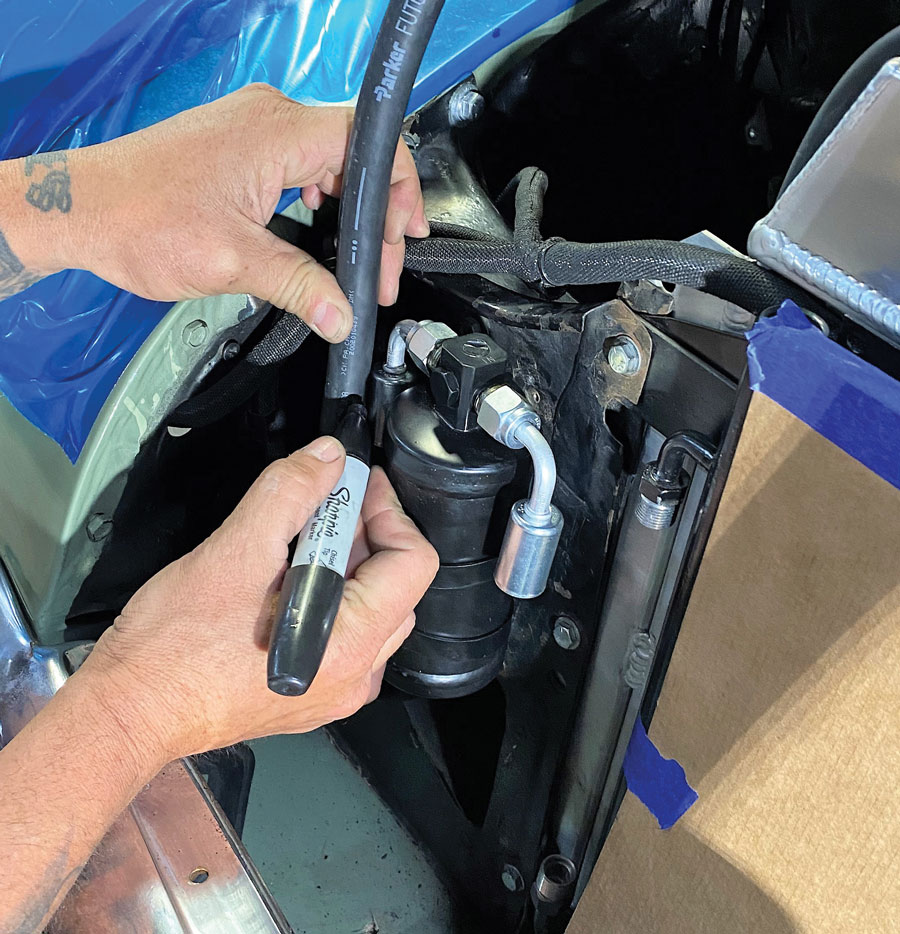
Before taking everything out of the box and jumping directly into the installation, keep this in mind. It’s critical that the compressor, evaporator, A/C hoses and fittings, hardlines, condenser, and receiver/drier remained capped. Should you remove the caps too soon you run the risk of moisture seeping into the components, hence contaminating your system. (Go ahead, ask me how I know this! —B.B.) Pay particular attention to the receiver/drier as this is especially critical.
When you look at the faceplate of your Heritage Series A/C and heater you will see three knobs. There’s a Blower Speed Knob (“F” knob) and it does just what it implies, controls the blower speed that pushes the air out at a prescribed speed (volume). Next up is the Heat Knob (“H” knob) located in the middle of the faceplate. Yep, it controls the temperature. Lastly, to the far right, there’s a Thermostat Knob (“C” knob). It controls a mechanical A/C thermostat.
Fundamentally, an automotive thermostat controls the temperature of the evaporator coil rather than the temperature of the air. Its main purpose is to prevent ice from forming between the fins of the coil. Should icing occur the A/C performance will be degraded. By adjusting the “C” knob with its arrow pointing straight up, the thermostat will turn the compressor off at approximately 34 degrees F. As a result, no ice will be allowed to form on the coil. Sometimes, in areas of very low humidity, such as Phoenix, it’s possible to adjust the thermostat colder and ice will not form.
As for day-to-day operation of the Heritage system, VA recommends always running the evaporator as cold as possible by positioning the “C” knob (right) with the arrow pointing straight up. You can then achieve the desired temperature by blending in heat using the “H” knob (center). Should you find yourself at the Louisville Nationals or other hot and humid events and want max cool then position all (three) knobs with the arrows pointing straight up.
Pretty much doesn’t matter where we live, all of us experience some form of “winter.” Keep this in mind: It’s helpful to run the A/C compressor to dehumidify the interior and reduce the potential for window fogging. To achieve this, run the “C” (thermostat knob) with its arrow pointing straight up, or back it off slightly as desired. Should you find yourself out on a particularly cold morning, you can achieve “max heat” by positioning the “C” knob to is full counterclockwise position (compressor off) and the “H” knob to its full clockwise position (heater control valve fully open). ( Modern Rodding contributing editor Chuck Vranas often finds himself a bit chilled on those Boston winter mornings. —B.B.)
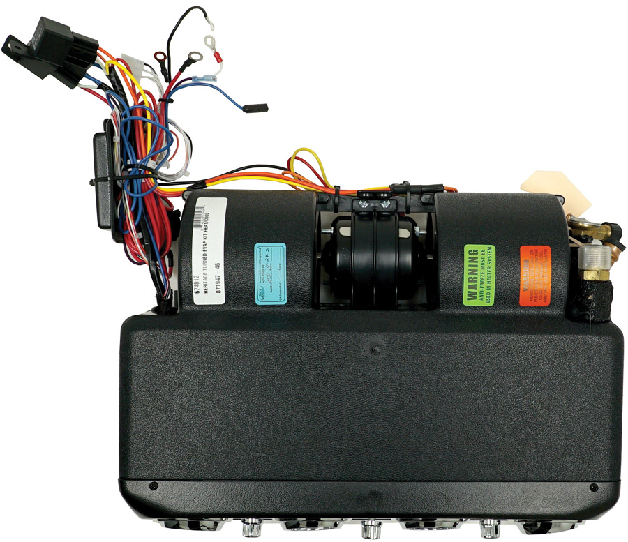
For proper condensate drainage, it’s important to mount the evaporator level on its four axes—front to back and left to right. The VA Heritage unit was designed for street rods, custom cars, and trucks, and as such the evaporator is intended to be mounted under the dash.
Best way to confirm this, rather than just “eyeball” it, is to grab your handy bubble level from your toolbox and place it on the bottom of the case. (You know the level you should have used to make sure your engine/trans, chassis, and body are all in proper perspective. Check with the detailed VA instructions on page 7 to confirm.) The left-to-right perspective should be as level as possible, no cheating here. The front to back may have up to 2 degrees tilt toward the drain outlets (louvers up).
This is all checked during the test-fit stage. Final mount of the evaporator will not occur until you have verified that all hoses attaching to the evaporator will exit the firewall and/or kick panel as planned. Remember, “Plan your work and then work your plan,” and a bit of added philosophy, “Measure twice, cut once.”
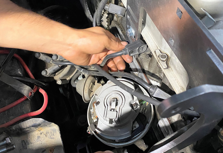
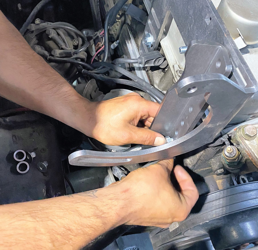
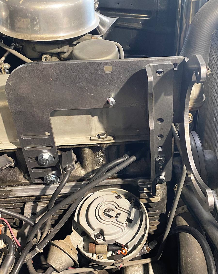
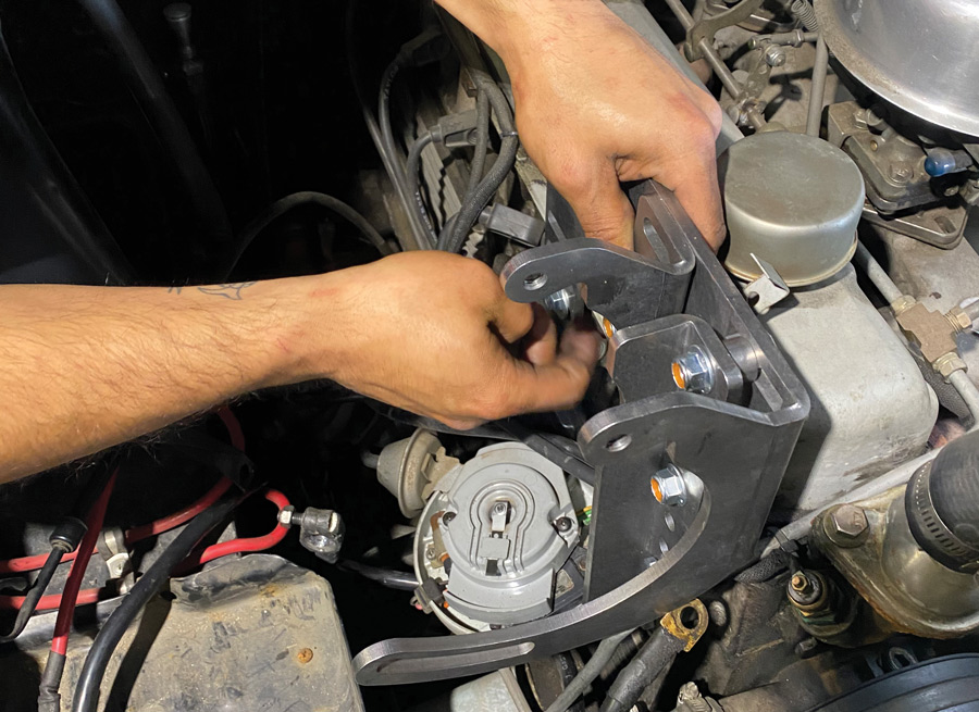
There are left and right and upper mounting brackets provided and these are somewhat “flexible” in their use. The left and right mounting brackets can be switched side-to-side and the rear upper mounting bracket can be trimmed or bent as needed. The hardware provided are ¼-20x½-inch hex bolts with 0.625-inch od by 0.281-inch id flat washers.
When planning for the drain hose keep the following in mind. First, when determining the drain location, consider the following: Drain hose must be installed with a minimum 1-inch drop from the evaporator case to the point where the hose exits and does so directly onto the ground. The drain hose and tee can be assembled in any configuration that meets these requirements, remembering that there’s a drain outlet on either side of the evaporator that needs to be accounted.
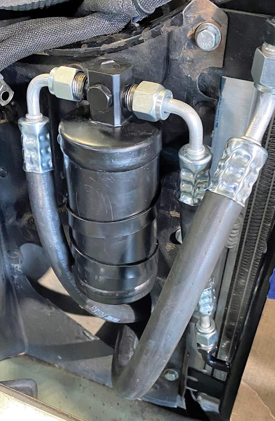
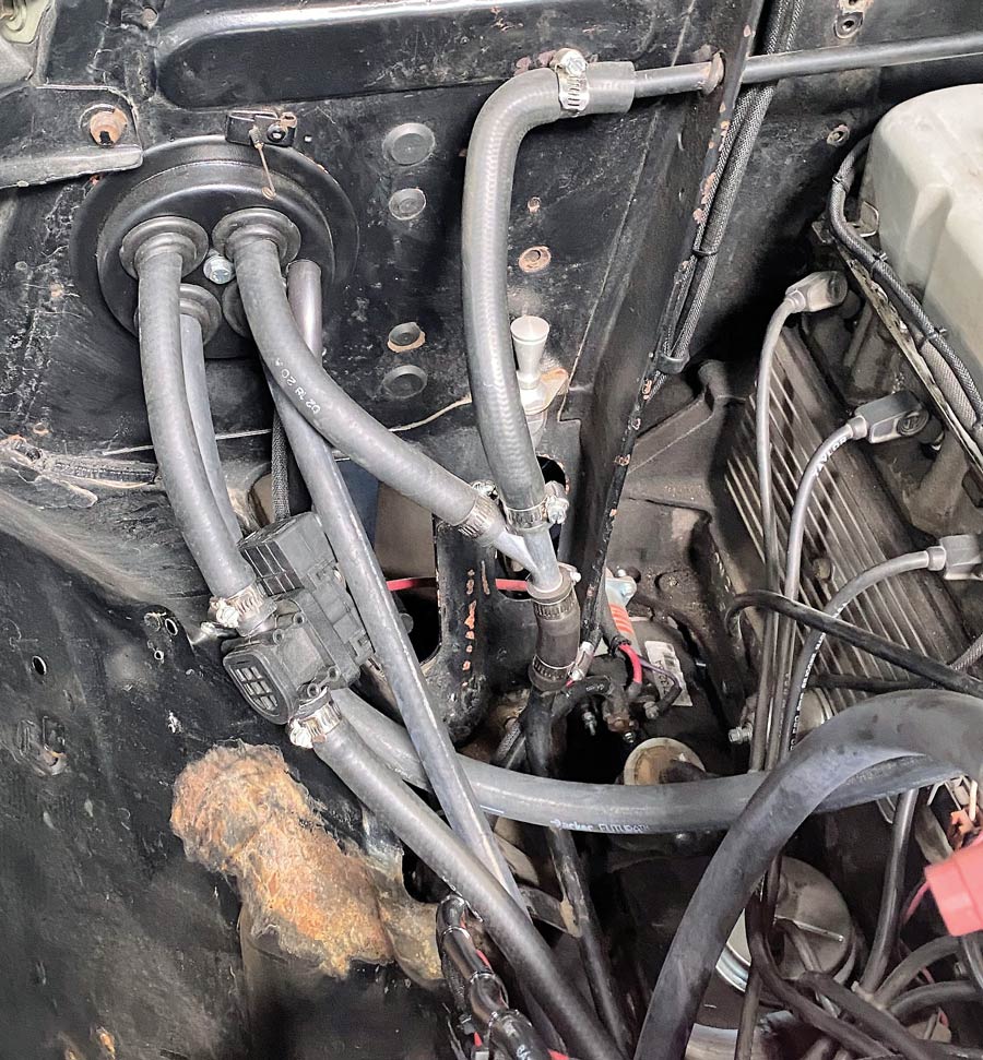
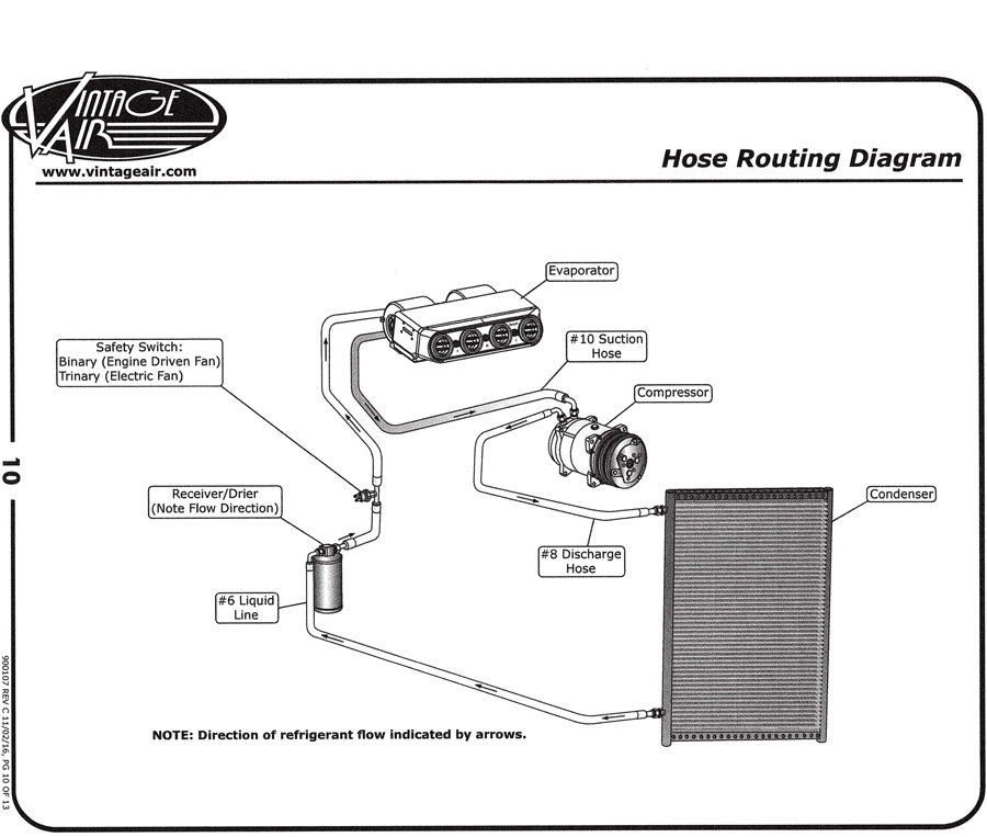
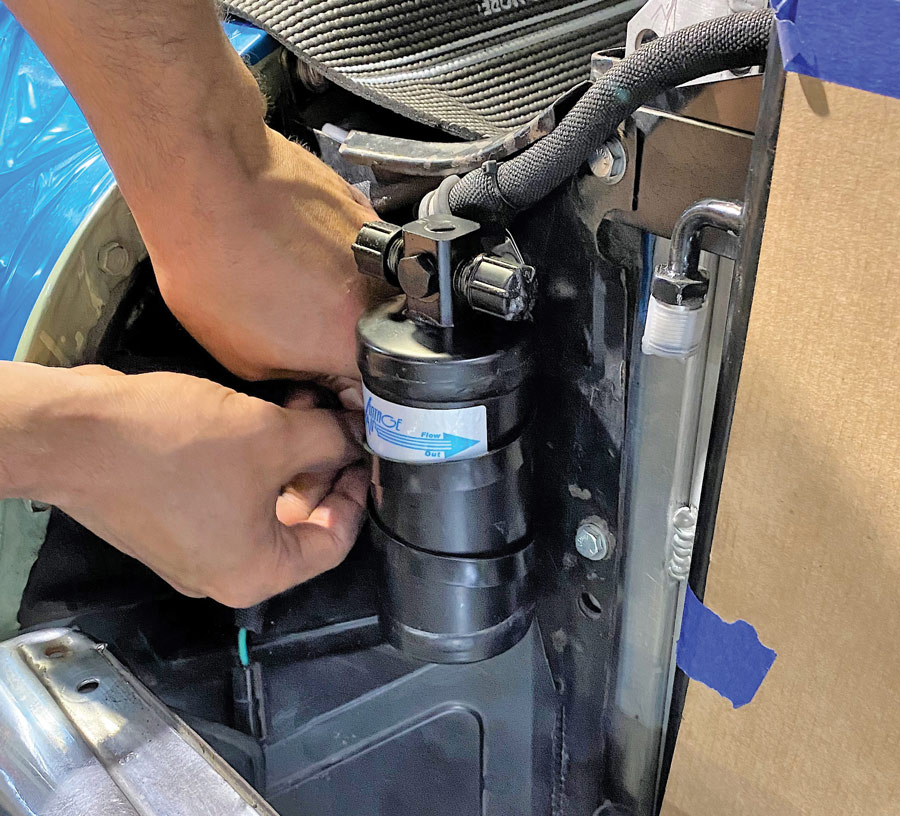
Something VA’s Love told us he sees all too frequently is an improperly mounted drier. There are several “dos” and “don’ts” when it comes to the drier. You “do” want to mount it where you have room, you “do” want it in the coolest spot you can find (inside the passenger compartment is fine and mounted to the core support in front of the radiator off to one side will also work). But the biggest “don’t” is to improperly mount the drier, which means mounting it in such a way that it isn’t within 20 degrees or so of vertical. Do not mount the drier upside down, and note that the drier is directional. The #6 line from the bottom of the condenser connects to the male threaded inlet labeled “in” and the hose leading to the evaporator will connect to the adjacent outlet.
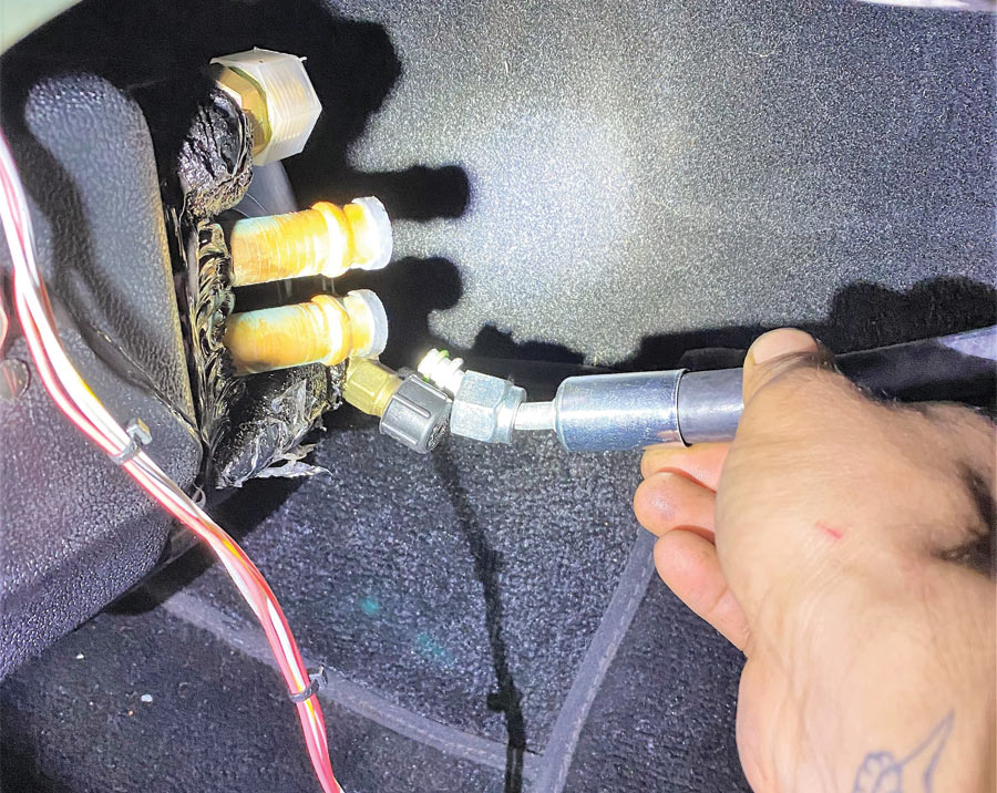
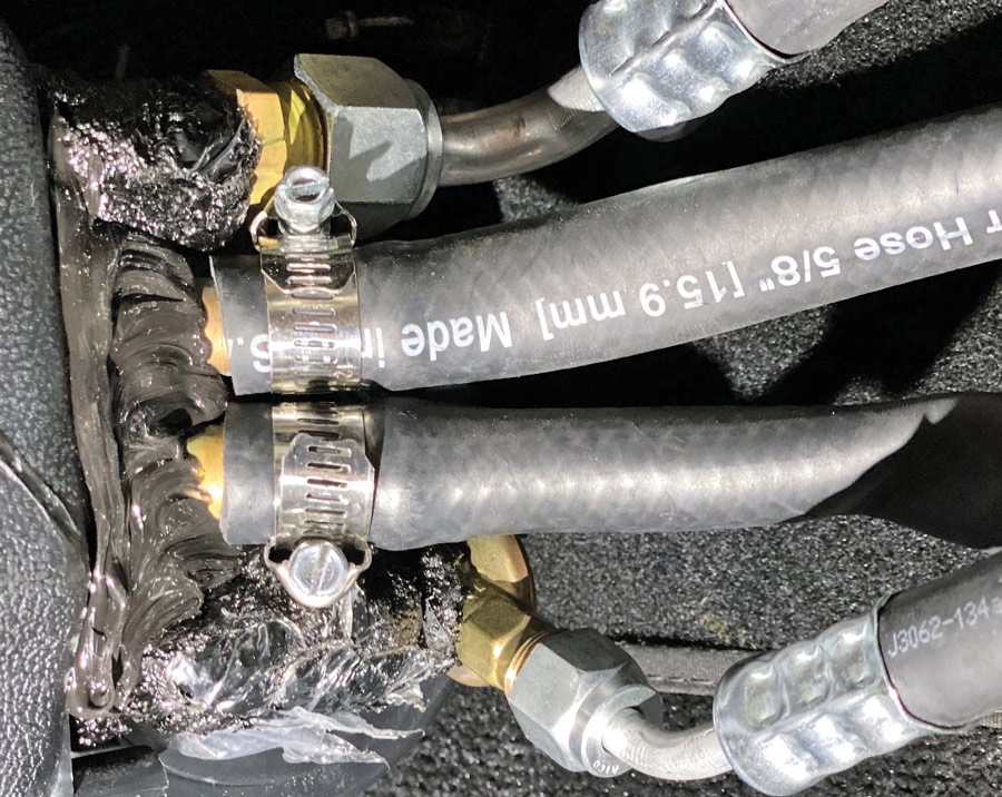
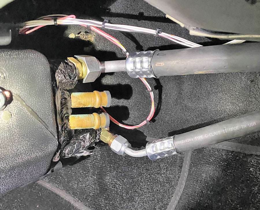
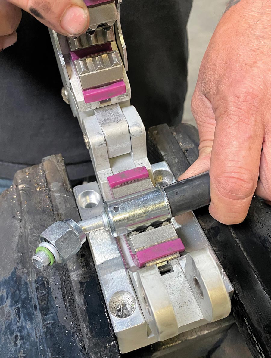
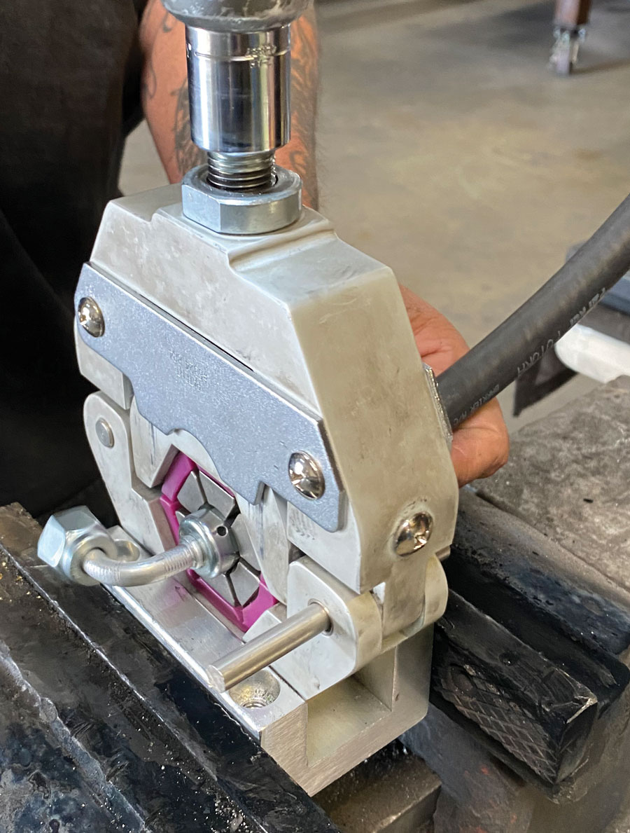
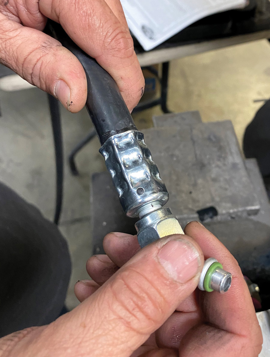
There’s a litany of things to do when cutting, affixing the fittings, and lubricating the O-rings. Best to refer to page 8 of the instruction manual for this—and follow the instructions.
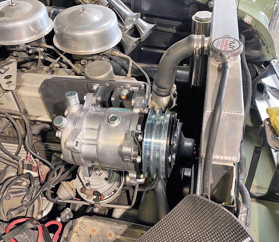
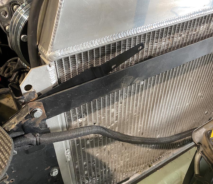
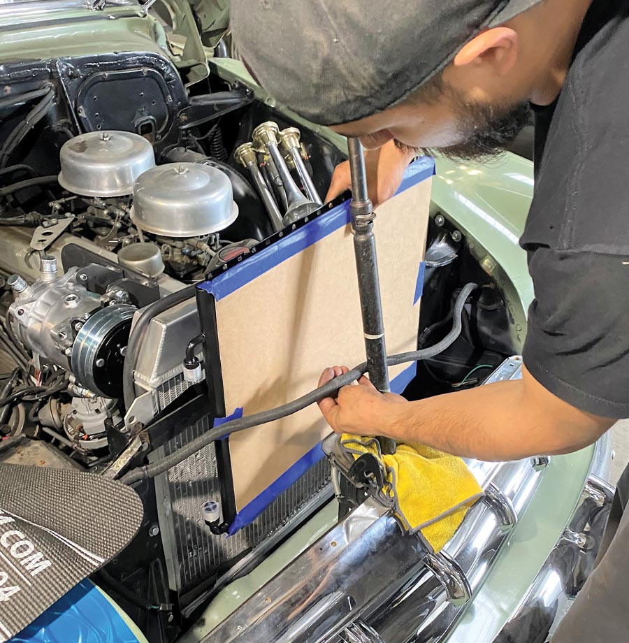
A word on the system’s condenser. VA always wishes to supply the largest condenser that will fit a certain application. As for fitment, its most desirable position is in front of the radiator. Love tells us that 1/8 of an inch is a good target for the gap between the condenser and radiator cores. The radiator and condenser are both heat exchangers and you want proper air to flow through both so that they function optimally.
Again, according to Love: “The condenser is your heat exchanger that dissipates the heat absorbed inside the car. Just like the evaporator, we want to use the largest heat exchanger possible, using the radiator core dimensions as the guide.”
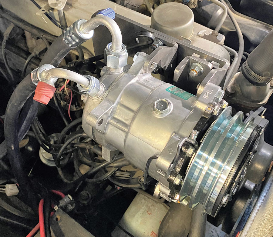
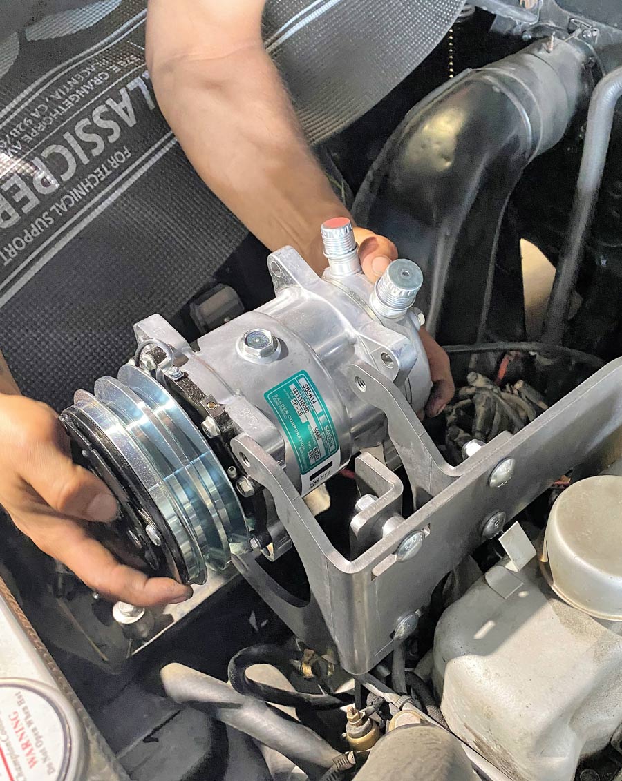
Matching a compressor to the job is also another important aspect. VA uses the 508 Sanden compressor for many of their applications, including the installation shown here. Love gave us some additional insight to this compressor.
He told us: “The capacity of a 508 is a good choice in most aftermarket cases for a compressor because with any A/C system you want to match your components. You don’t want a compressor with too much capacity, going with a condenser that’s too small because you’re just pushing more refrigerant through that condenser, and then you’re going to end up with head pressure issues. When I’m doing seminars, I always talk about matching components and I’ll say, ‘It’s no different than a brake system.’ When you want to use the latest four- or six-piston calipers with your 14-inch rotors, you’ve got to make sure that your master cylinder bore size and pedal ratio are matched to deliver the amount of brake fluid that you need. If you’ve got a mismatch master cylinder you’re not going to have adequate performance out of those brakes. Same for the A/C system.”
Another question that pops up frequently, “Which size line is at the top and which is at the bottom on the condenser?” Love told us to always make sure that the #8 (the big one) is on top and the #6 (the small one) is on the bottom. You have high-pressure gas going into the top of the condenser and high-pressure liquid coming out at the bottom. We are reminded by Love that liquid is heavier than gas so you want the liquid on bottom and the gas on top.
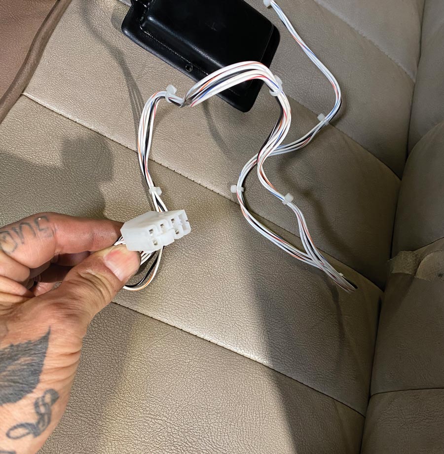
A little on the electrics of the A/C system. VA includes in their wiring harness a 30-amp circuit breaker. They also recommend going directly to the battery (or starter) for power. This is done so that you are confident that you are carrying all of the current load in a new GSL wire. It’s never a good idea to try and hook directly to a fusebox on an early car and then pull the heavy amperage load. The optimal situation would be to have a new wiring system, such as an American Autowire kit, that plans for A/C and all of the proper connections are provided.
Well, there you have it; it’s time to be oh-so cool on the oh-so hot days!
recommendations.