

PHOTOGRAPHY BY THE AUTHOR, BRIAN BRENNAN & TODD RYDEN
t’s been said that the secret to success in life is really a matter of timing—being in the right place at the right time. While it may be a stretch as metaphors go, the same thing can be said about the basic ignition and timing in your hot rod. Delivering the spark that ignites combustion at the right time is the key to performance. The problem is that the right time for it to occur changes with a variety of factors.
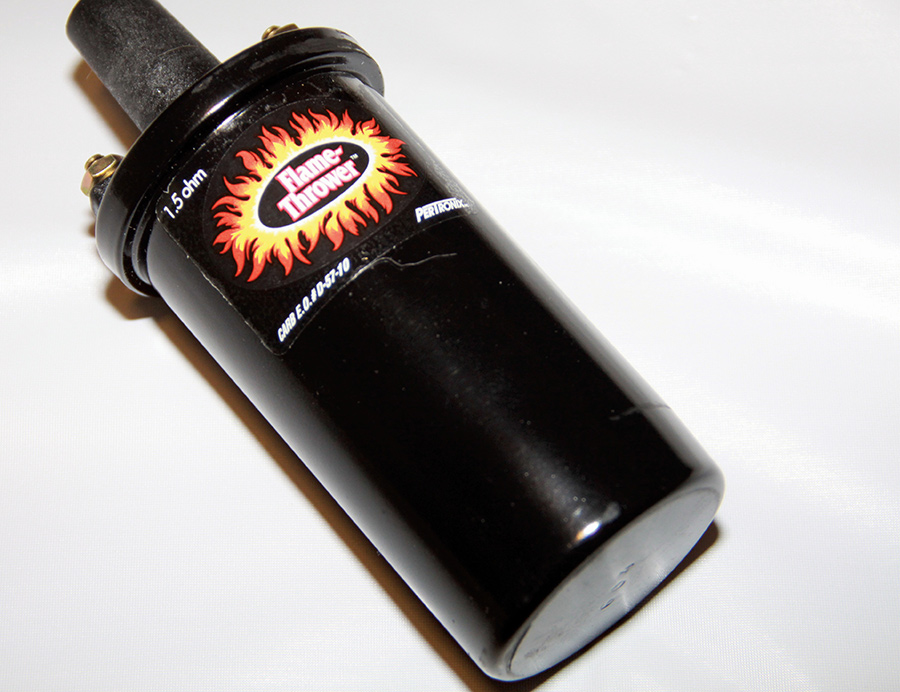
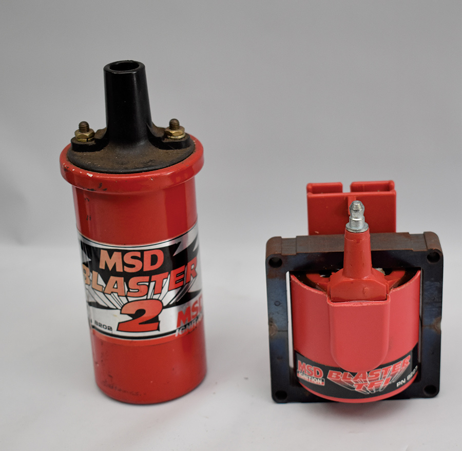
Before delving into basic ignition and timing, let’s look at the basic operation of the ignition system. If you’ve ever wondered who figured out how to take battery voltage and bump it up to 25,000 V or more to fire the spark plugs, the credit goes to a guy named Charles F. Kettering. He developed the inductive ignition system first used on the 1912 Cadillac; that basic system is still in use today. In operation, the original Kettering system used a coil (a step-up transformer) to increase battery voltage. Current from the ignition switch passed through a set of points (a mechanical switch) in the distributor, then through the coil’s primary windings, creating a magnetic field. When the points opened, the magnetic field collapsed, inducing voltage in the secondary windings of the coil, which had many more turns of wire than the primary (there was also a condenser in the system to keep the points from arcing). The high voltage from the coil’s secondary windings was delivered to the distributor cap. The rotor sent spark to the appropriate cylinder, and the process repeated as the rotor turned to align with the next spark plug terminal. The amazing thing about Kettering’s ignition system is that the basic concept remains in use today. The one major change has been the elimination of mechanical points that required periodic maintenance. Today electronics do what the points once did, but the function of the basic ignition and timing system remains the same.
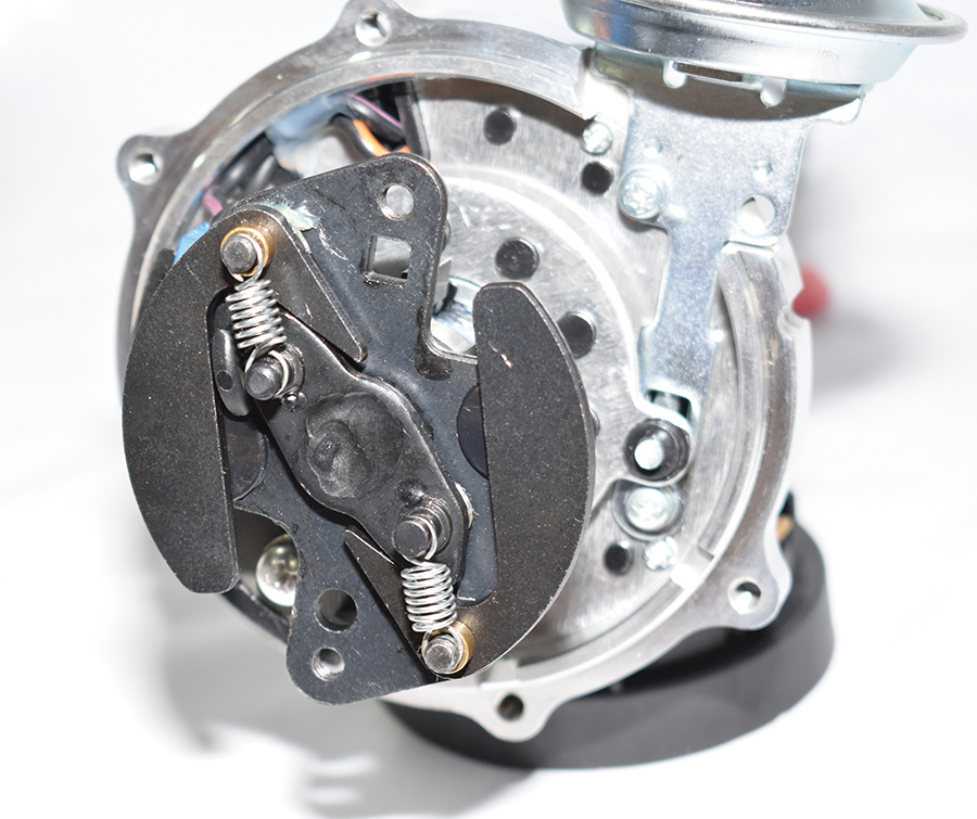
Along with creating the spark needed to ignite the air/fuel mixture in the cylinders, the basic ignition and timing system also controls when it occurs. That’s done in three ways: initial ignition timing (which is fixed), a centrifugal advance system that varies timing with engine speed, and a vacuum advance system that varies timing with engine load.
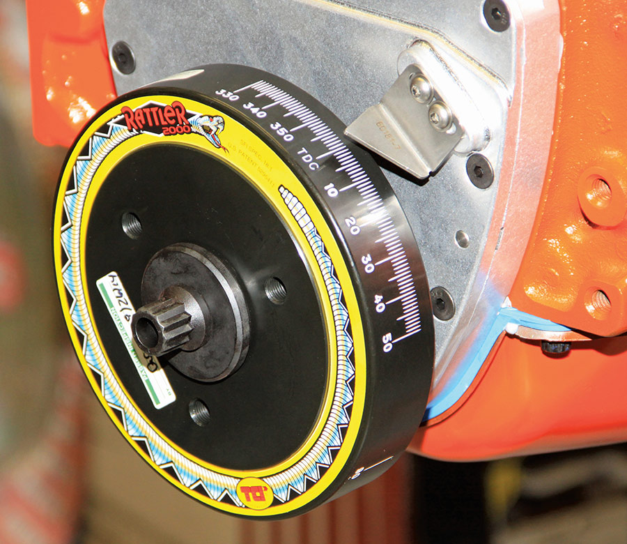
Initial, or base, timing is the setting that allows the engine to start and run. The air/fuel mixture takes time to burn, so initial timing is set a few crankshaft degrees before the pistons reach top dead center (TDC). Not enough initial advance makes the engine “lazy” off idle and hard to start because maximum cylinder pressure from the burning fuel arrives too late in the piston’s travel. Too much initial advance causes cylinder pressure to build too soon, causing the engine to “kick back” against the starter.
For more years than either of us will admit, Henry Olsen of Performance Motorsports (performancemotorsports1581.com) has been our go-to for advice on tuning ignition systems (fuel systems too, but that’s for another time). As Olsen explains, “The ideal ignition spark timing for power will cause peak cylinder pressures from the combustion process to occur around 12 to 15 degrees ATDC (after top dead center). If the peak cylinder pressure is reached too early, the engine will experience pinging or detonation, which can cause the engine to lose power as the piston fights to compress the burning air/fuel mixture—and can also lead to piston failure if not corrected. Conversely, if peak cylinder pressure is reached after the 12- to 15-degree ATDC range, the energy in the air/fuel mixture will still be burning as the exhaust valve opens, and it will go out with the exhaust as wasted energy.”
While it’s impossible to suggest the ideal timing specifications for all engines, longer-duration cams will require more initial advance. Olsen typically recommends 10 to 12 degrees of initial timing for an engine with a camshaft up to 220 degrees of duration, 14 to 16 degrees with a camshaft up to 240 degrees, and 18 to 20 degrees with a duration of 260 degrees or more. Keep in mind that whenever the initial timing is altered, the total ignition advance must be checked to ensure there is no detonation or pinging.
Another consideration is the rate at which mechanical advance occurs. In original equipment distributors, the rate of spark advance is often very conservative, with total mechanical advance not “all-in” until the engine reaches 5,000 to 6,000 rpm. Most new performance distributors also have conservative advance curves, but the best ones include the parts and instructions needed to tune them to match the engine’s needs. Olsen advises that the mechanical spark timing advance system for most performance engines should not begin advancing until the engine is 100 to 150 rpm above the engine’s normal idle speed, with total mechanical advance all in by 3,000 to 3,500 rpm, as long as the engine does not ping or detonate. He adds, “A typical modern crate engine with ‘fast-burn’ cylinder heads will produce maximum power at wide-open throttle with a total mechanical ignition timing (initial plus mechanical advance) in the 30- to 34-degree range.”
The last system we’re looking at is the vacuum advance. When an engine is operating under a light load at part throttle, the manifold vacuum is high and the fuel system supplies a lean air/fuel mixture. Leaner mixtures burn more slowly, so the vacuum canister advances the timing. A vacuum advance system can help increase fuel efficiency and allow the engine to run cooler because more of the energy from the combustion process is converted into useful work, and less (unburned fuel) goes out with exhaust as wasted heat. Of course, for race applications the vacuum advance issue is irrelevant, as performance at wide-open throttle is the only concern, but for street use a vacuum advance should be included.
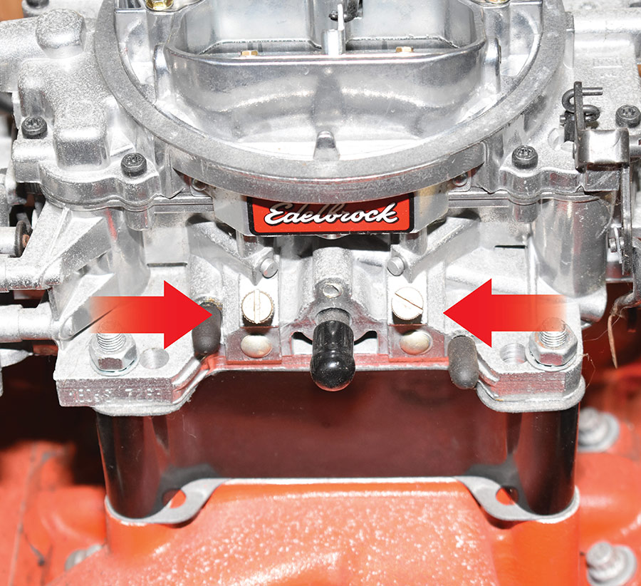
There are usually two vacuum sources for the vacuum advance: ported vacuum, which gets its signal from a carburetor port above the closed position of the throttle plate; and manifold vacuum, which is the actual vacuum in the intake manifold when the engine is running. Opinions vary on which vacuum source is best. When manifold vacuum is used, the spark timing at idle will advance an additional 10 to 24 degrees, depending on the available vacuum and the design of the vacuum canister. In some cases, with an aggressive cam, this will improve idle quality, but the initial advance may have to be reduced and the advance curve modified.
In his testing, Olsen has found that most of the vacuum advance available today was designed to work with a gasoline blend that no longer exists. As a result, it tends to supply too much advance for today’s reformulated gasoline. Today’s gasoline is harder to ignite or less volatile than the gas from the ’50s, ’60s, and ’70s, but it burns somewhat faster than leaded gasoline. Thus, the need is for more initial timing, about the same mechanical total advance, but less timing from vacuum advance. If an engine gets too much vacuum advance, it can cause a misfire, often described as “bucking” or “trailer hitching.” Olsen’s experience has shown that with today’s fuels, limiting the vacuum advance to 10 to 12 degrees after the initial timing and mechanical advance have been optimized works best. This has been confirmed by driveability tests and by examining the engine misfire rate (HC reading) and engine efficiency (CO2 reading) using an exhaust gas analyzer.
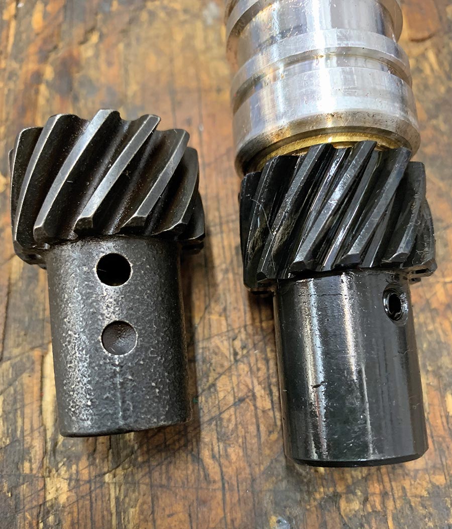
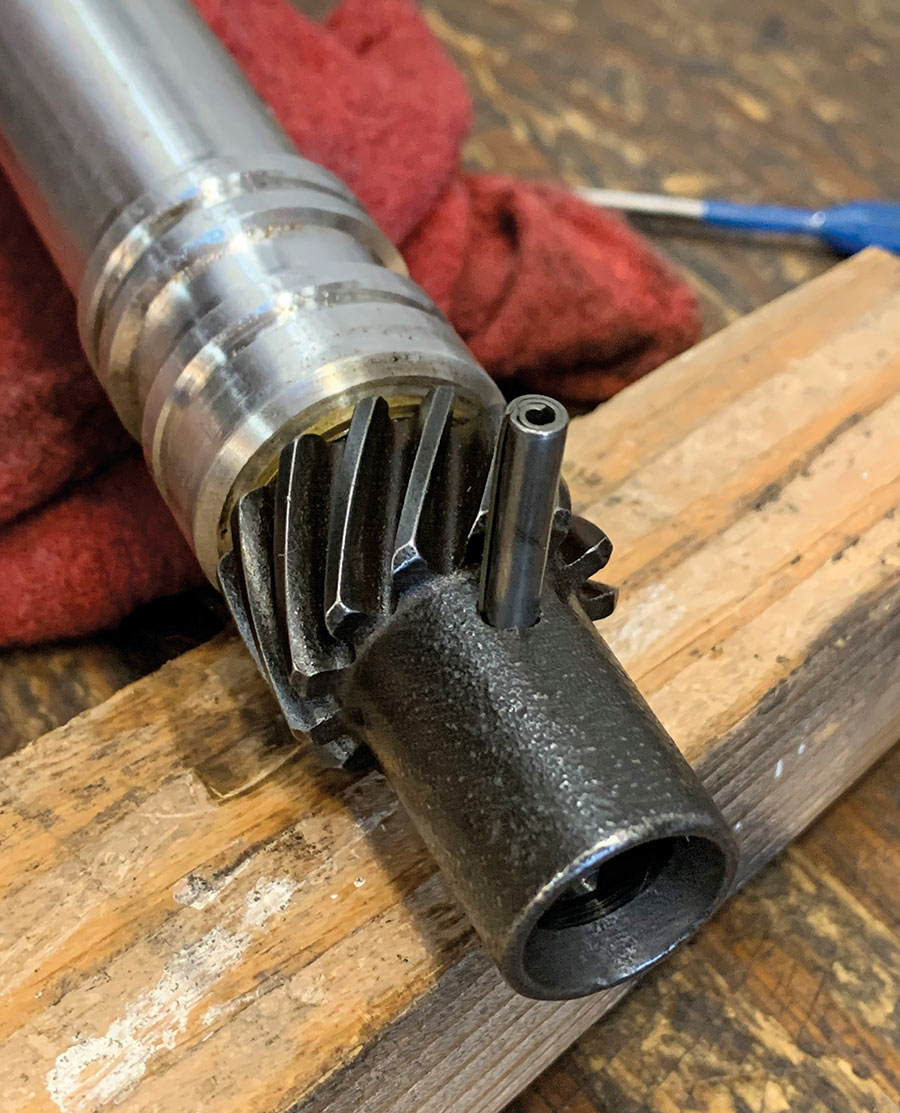
Oddly enough, premature distributor drive gear wear has become problem roller camshafts. It is essential that the distributor and cam gears are compatible. The types of distributor gears are:
CAST IRON: used with cast-iron flat-tappet cams, these gears are harder than bronze and composite gears but softer than melanized.
MELANIZED: for use with ductile iron and billet steel roller cams. The thermochemical process produces a tough, unique, dimpled, or speckled finish.
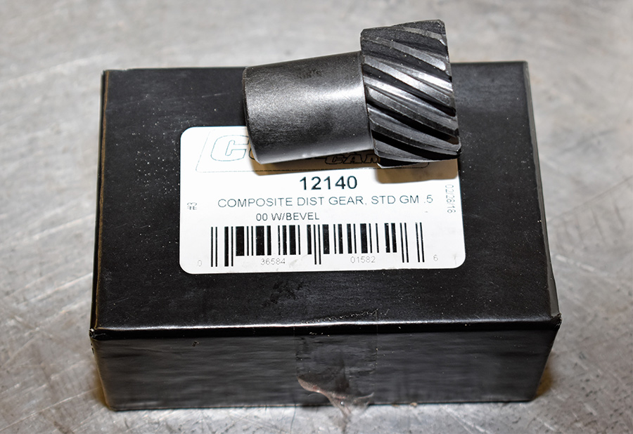
COMPOSITE: compatible with all camshaft materials but is the most expensive option.
BRONZE: used with billet-steel cams. These are sacrificial and should be replaced when wear becomes evident.
Although we’ve been dealing with basic ignition and timing systems, using a conventional distributor, the most modern computer-controlled systems without distributors have coils that operate the same way they did in 1912. Of course timing requirements have changed over the years due to efficiency improvements and differences in available fuel, but it’s still important to ignite the fuel in the cylinder at the right time because timing is the secret to success.