Modern Rodding TECH

InTheGarageMedia.com

 Left to right, Ryan Foss (videographer), Wilwood’s Mike Hamrick, and Modern Rodding Tech Center Manager Jason Scudellari begin the installation of Wilwood’s Electric Parking Brake (EPB) components on Brian Brennan’s ’29 Ford roadster. In this case the roadster was originally equipped with internal parking brakes (IPB).
1. Left to right, Ryan Foss (videographer), Wilwood’s Mike Hamrick, and Modern Rodding Tech Center Manager Jason Scudellari begin the installation of Wilwood’s Electric Parking Brake (EPB) components on Brian Brennan’s ’29 Ford roadster. In this case the roadster was originally equipped with internal parking brakes (IPB).
By Ron Ceridono
Photography by BRIAN BRENNAN
Videography by RYAN FOSS PRODUCTIONS
Brake Time
Installing Wilwood’s Electric Parking Brake System
A

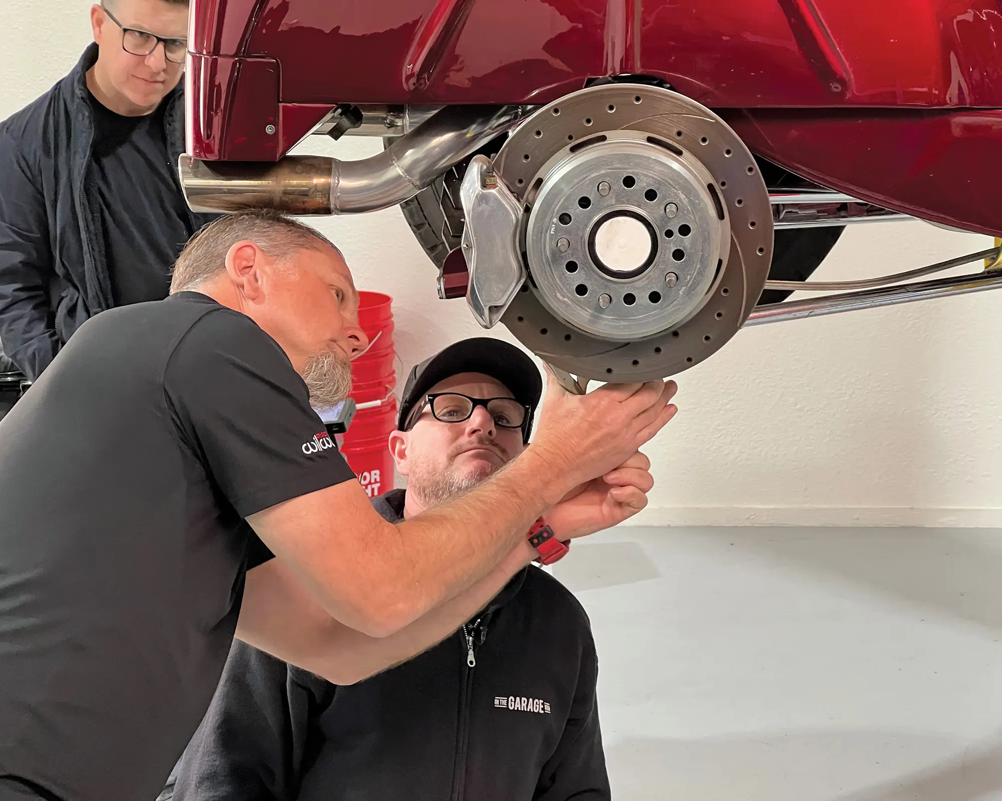
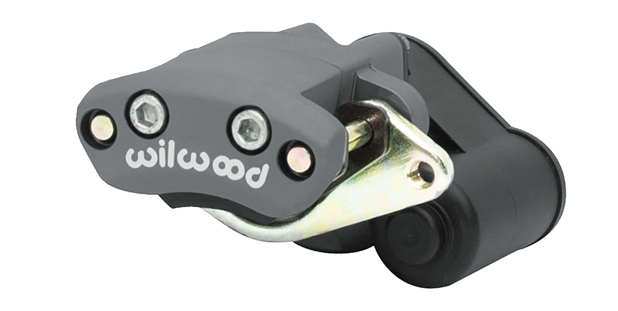
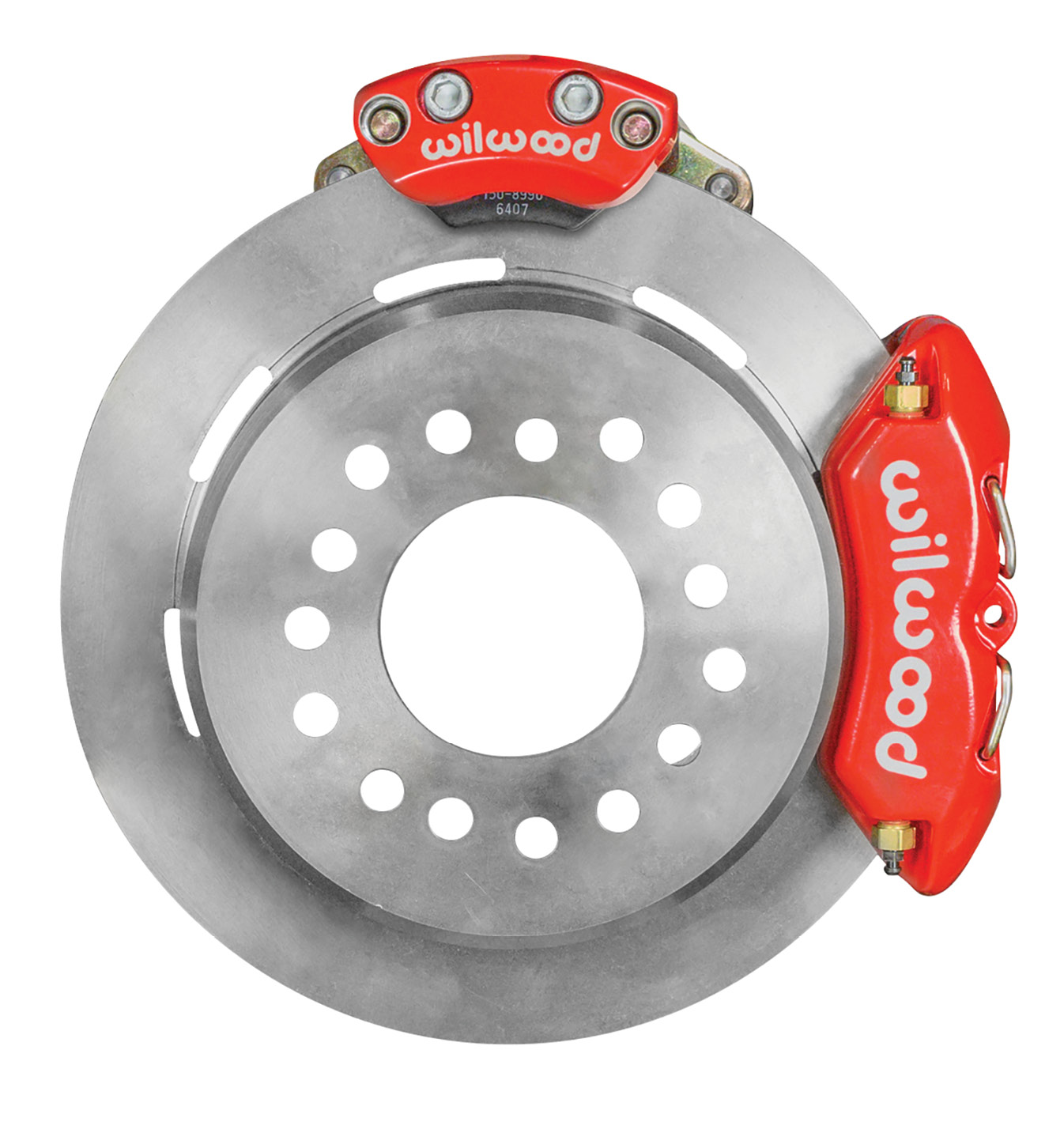
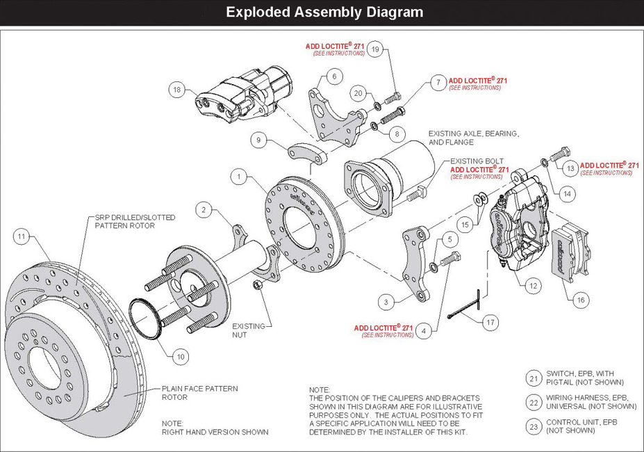
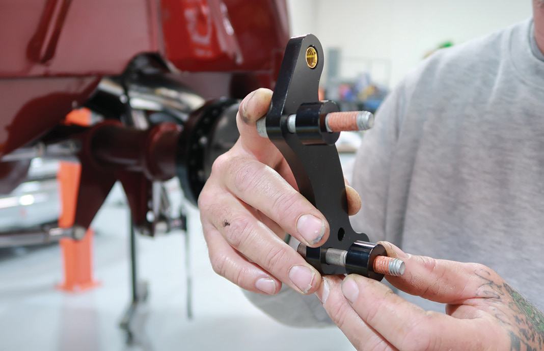
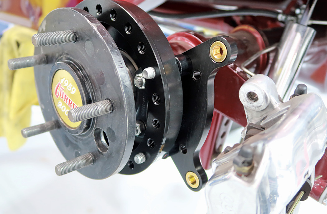
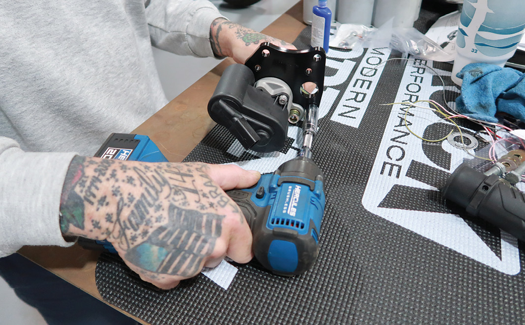
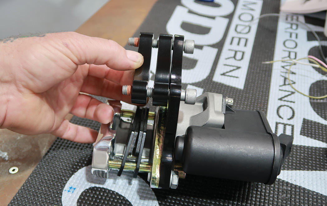
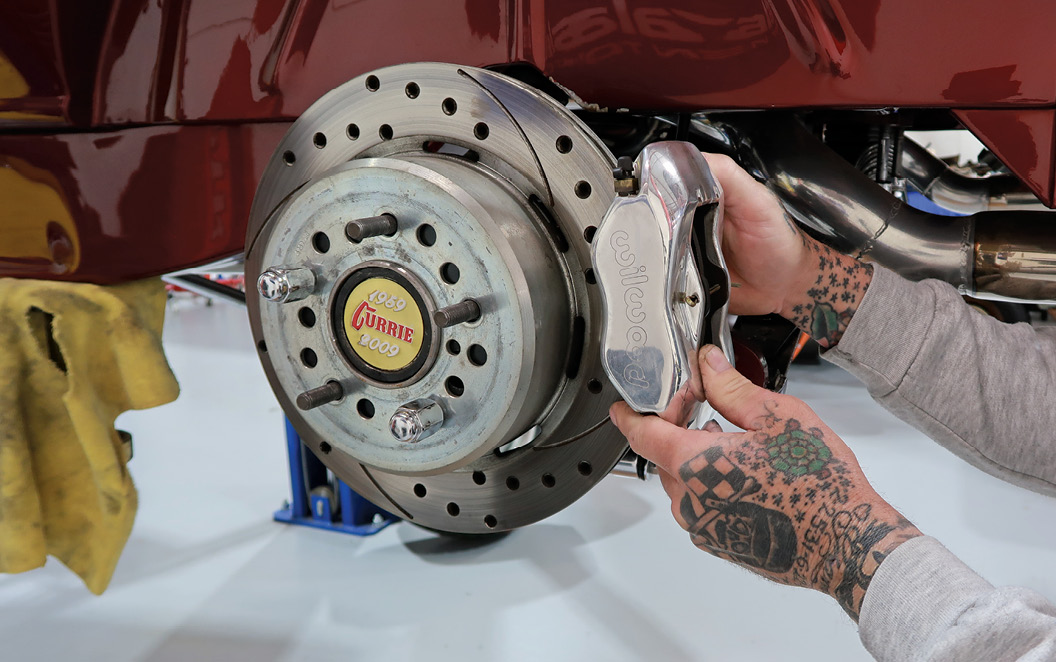
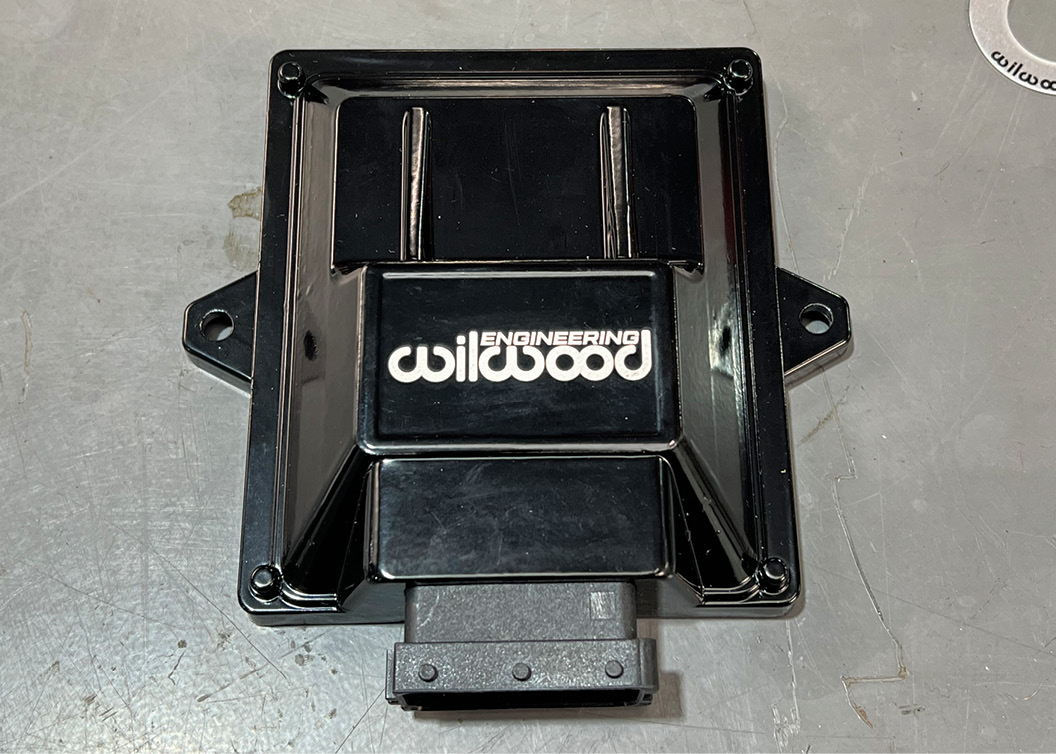
nyone who has been around performance vehicles recognizes the name Wilwood Engineering. Founded by Bill Wood in 1977, Wilwood is a leading manufacturer of cutting-edge, high-performance disc brakes and related components. One of their newest products is the Electric Parking Brake (EPB) system that eliminates cables and conventional actuation levers. Wilwood’s EPB kits include calipers, pads, brackets, hardware, control module, switch, wiring harness, and detailed installation instructions.

It’s interesting how the description of some automotive parts has changed over the years. As an example, the term emergency brake was once used to describe the system that was originally intended to be used in the case of a main brake system failure (not to mention Brennan by name, but lots of older editors still call it the emergency brake). Of course, as automobile technology evolved there was often a change in nomenclature as well and the emergency brake came to be more accurately described as the parking brake for obvious reasons. But regardless of what you call it, hot rods need one. Relying on leaving your car in gear or in Park can be risky. Take it from someone who watched his roadster try to roll away when it was assumed to be in Park and wasn’t as proof positive that an effective parking brake is a wise addition to any car.

The EPB calipers are made of forged aluminum and are equipped with weather-resistant, high-torque motors that produce a minimum 2,400 pounds of clamping force on the discs—enough to keep any hot rod in its place. The calipers are controlled by a microprocessor that is activated by a momentary contact rotary switch. When the calipers are activated (brakes applied) there is a momentary 40-amp draw. When the calipers are released the momentary amp draw is approximately half of that. The red indicator light on the EPB control switch will illuminate when the EPB is engaged, but only while the ignition is on.

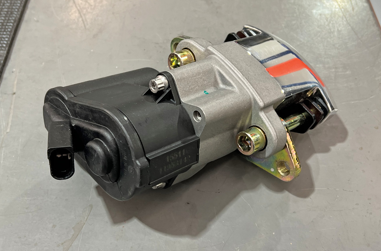
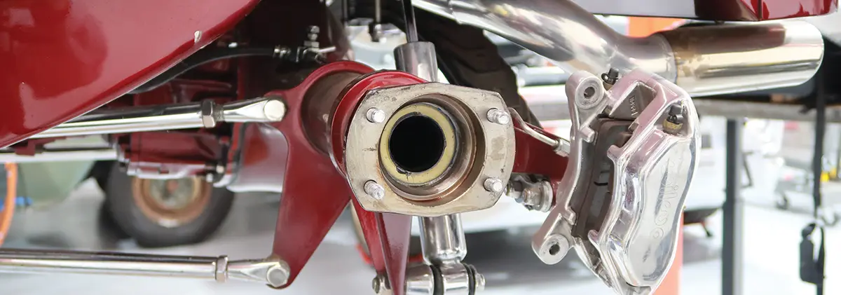
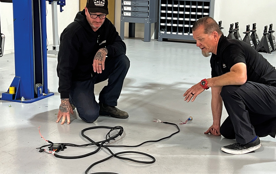
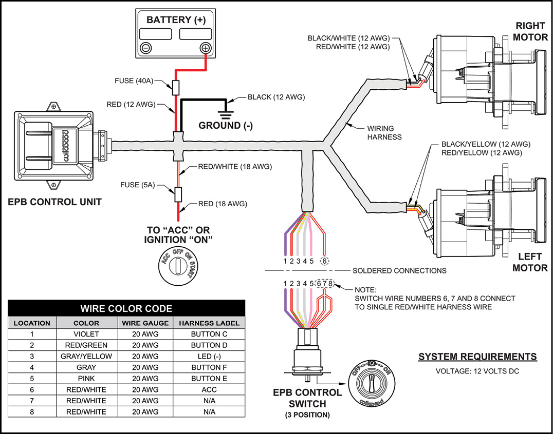
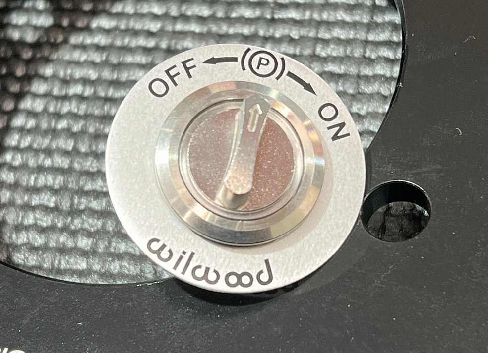
Current is only required to turn the EPB calipers on and off. So should something unexpected happen, such as the wiring harness being damaged by a hot exhaust pipe while traveling, there is no chance that the system will apply with the car in motion. In addition, the indicator light on the control switch will flash if there is a fault in the system, such as damaged wiring.

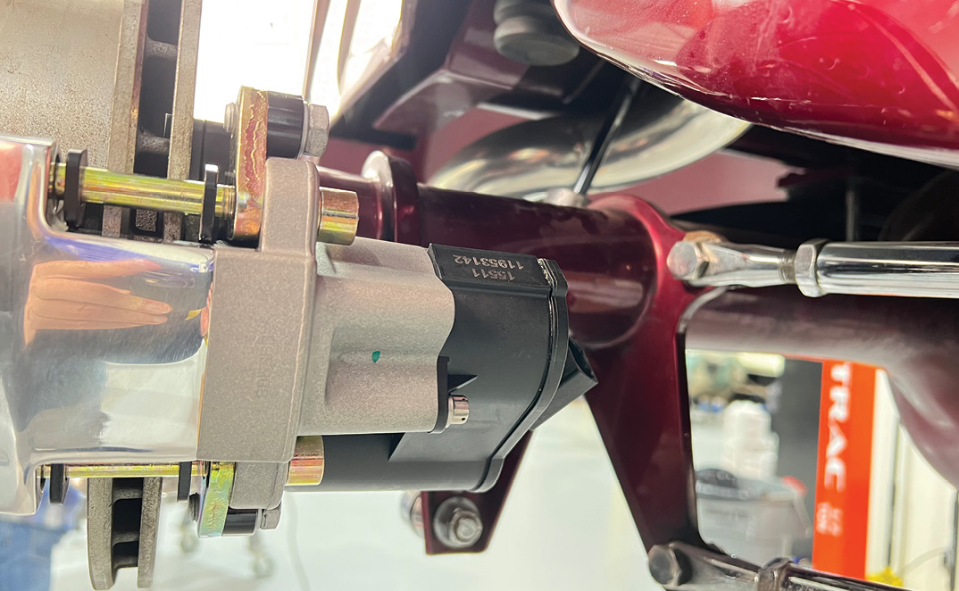
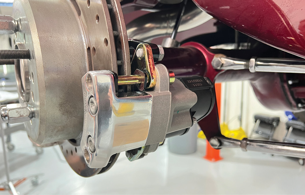
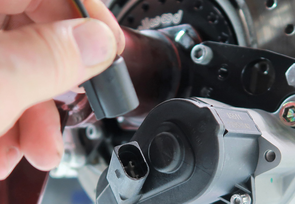
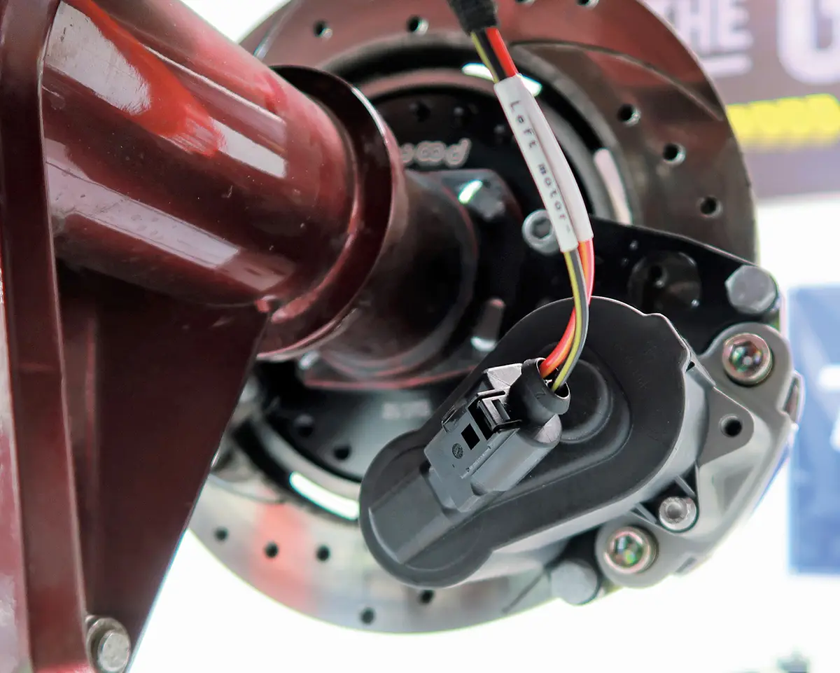
Another obvious question is, “What happens if I store my car with the EPB set and the battery goes dead. As Mike Hamrick from Wilwood explains it, there are two simple solutions: charge the battery enough to release the brakes or take the wheels off and release the two 1/4-20 bolts that hold the electric motors in place so the pistons will release and the car may be moved.

Like every other brake product Wilwood offers, the EPB system is well designed, extremely effective, and good looking to boot. Some may still call a parking brake an emergency brake, but whatever you call it your hot rod should have one.

Wilwood’s EPB calipers are compact and available in gloss red or black powdercoat, polished aluminum, or Type-III hard anodized coating.
2. Wilwood’s EPB calipers are compact and available in gloss red or black powdercoat, polished aluminum, or Type-III hard anodized coating.
The Wilwood EPB electric caliper uses a geared motor assembly to provide 2,400 pounds of clamping force. Right- and left-hand motor options are available for ease of installation.
3. The Wilwood EPB electric caliper uses a geared motor assembly to provide 2,400 pounds of clamping force. Right- and left-hand motor options are available for ease of installation.
EPB calipers are available to retrofit existing systems as we did, or as part of the complete new Wilwood brake kits that also come with new rotors and hydraulic calipers. A typical kit is shown here (the necessary brackets and hardware are also included).
4. EPB calipers are available to retrofit existing systems as we did, or as part of the complete new Wilwood brake kits that also come with new rotors and hydraulic calipers. A typical kit is shown here (the necessary brackets and hardware are also included).
Wilwood’s variety of brackets allows the calipers to be mounted where they fit the best.
5. Wilwood’s variety of brackets allows the calipers to be mounted where they fit the best.
Determining the axle flange offset is critical to selecting the proper mounting brackets to properly locate hydraulic and EPB calipers in relationship to the rotors.
6. Determining the axle flange offset is critical to selecting the proper mounting brackets to properly locate hydraulic and EPB calipers in relationship to the rotors.
Here is one of the backing plates that attaches to the axle housing—in turn the hydraulic and EPB caliper mounting brackets attach to the backing plate.
7. Here is one of the backing plates that attaches to the axle housing—in turn the hydraulic and EPB caliper mounting brackets attach to the backing plate.
This is the axle retainer that attaches to the axle housing. The open end of the bracket allows it to be installed with the axle in place unlike the OEM full-circle design.
8. This is the axle retainer that attaches to the axle housing. The open end of the bracket allows it to be installed with the axle in place unlike the OEM full-circle design.
These are the caliper mounting brackets, the hydraulic caliper bracket on the left, EPB bracket on the right.
9. These are the caliper mounting brackets, the hydraulic caliper bracket on the left, EPB bracket on the right.
This exploded view shows the relationship of all the rear brake components (although the positions of the calipers may vary).
10. This exploded view shows the relationship of all the rear brake components (although the positions of the calipers may vary).
Installing the Wilwood backing plate requires removing the axle shafts. Not a bad time to install fresh axle seals.
11. Installing the Wilwood backing plate requires removing the axle shafts. Not a bad time to install fresh axle seals.
With the backing plate in place, Scudellari replaced the axle shaft in the Currie housing.
12. With the backing plate in place, Scudellari replaced the axle shaft in the Currie housing.
Next the axle retainer is put in place; the attachment bolts (with lock nuts) secure the backing plate and the retainer to the housing.
13. Next the axle retainer is put in place; the attachment bolts (with lock nuts) secure the backing plate and the retainer to the housing.
For security, a blue thread locker should be applied to all the caliper bracket fasteners.
14. For security, a blue thread locker should be applied to all the caliper bracket fasteners.
Access to the axle retainer/backing plate nuts is made easier by holes in the Currie flanges.
15. Access to the axle retainer/backing plate nuts is made easier by holes in the Currie flanges.
After measuring the axle flange offset, the proper combination of spacers is installed on the mounting bracket bolts to center the brake caliper on the rotor.
16. After measuring the axle flange offset, the proper combination of spacers is installed on the mounting bracket bolts to center the brake caliper on the rotor.
Here the brake caliper bracket has been bolted to the back side of the backing plate.
17. Here the brake caliper bracket has been bolted to the back side of the backing plate.
The EPB caliper is secured to the mounting bracket.
18. The EPB caliper is secured to the mounting bracket.
Spacers are then added between the mounting bracket and the backing plate<br />
to center the EPB caliper on the rotor.
19. Spacers are then added between the mounting bracket and the backing plate to center the EPB caliper on the rotor.
With the proper caliper location relative to the rotor verified it was reinstalled.
20. With the proper caliper location relative to the rotor verified it was reinstalled.
The EPB caliper was bolted in place and its location was verified (note that it is centered on the rotor).
21. The EPB caliper was bolted in place and its location was verified (note that it is centered on the rotor).
To allow full suspension travel the EPB motor has been positioned far enough below the frame to allow full suspension travel without interference.
22. To allow full suspension travel the EPB motor has been positioned far enough below the frame to allow full suspension travel without interference.
Scudellari and Hamrick laid out the EPB wiring harness to identify all the connectors.
23. Scudellari and Hamrick laid out the EPB wiring harness to identify all the connectors.
This is the control unit for the EPB system. It’s compact, measuring roughly 5 inches square and 1-1/4 inches thick.
24. This is the control unit for the EPB system. It’s compact, measuring roughly 5 inches square and 1-1/4 inches thick.
Wiring the EPB system is plug-and-play with one 12V constant source and one ACC or ignition on source.
25. Wiring the EPB system is plug-and-play with one 12V constant source and one ACC or ignition on source.
Inline fuses for the constant and switched power sources are included in the wiring harness.
26. Inline fuses for the constant and switched power sources are included in the wiring harness.
Once the EPB switch is installed, the wiring harness plugs in; it can only be installed one way.
27. Once the EPB switch is installed, the wiring harness plugs in; it can only be installed one way.
The EPB control switch is momentary; to operate there is no need to hold the switch in position. Rotate the switch clockwise to engage parking brake and counterclockwise to release.
28. The EPB control switch is momentary; to operate there is no need to hold the switch in position. Rotate the switch clockwise to engage parking brake and counterclockwise to release.
By installing the switch in a hidden location the EPB system also acts as a theft deterrent.
29. By installing the switch in a hidden location the EPB system also acts as a theft deterrent.
The wiring harness should be installed so as not to be damaged by the exhaust system or driveline components and protected with plastic loom rubber grommets if it passes through holes in sheetmetal.
30. The wiring harness should be installed so as not to be damaged by the exhaust system or driveline components and protected with plastic loom rubber grommets if it passes through holes in sheetmetal.
To problem-free connections the EPB caliper plugs and wiring uses weatherproof connectors.
31. To problem-free connections the EPB caliper plugs and wiring uses weatherproof connectors.
The electrical harness is simple to install, however note the wires for the EPB calipers are marked for the left and right motors.
32. The electrical harness is simple to install, however note the wires for the EPB calipers are marked for the left and right motors.
SOURCE
Wilwood
(805) 388-1188
wilwood.com
In the Garade Media - Tech Center - Frontier shop supplies
Modern Rodding
VOLUME 4 • ISSUE 37 • 2023