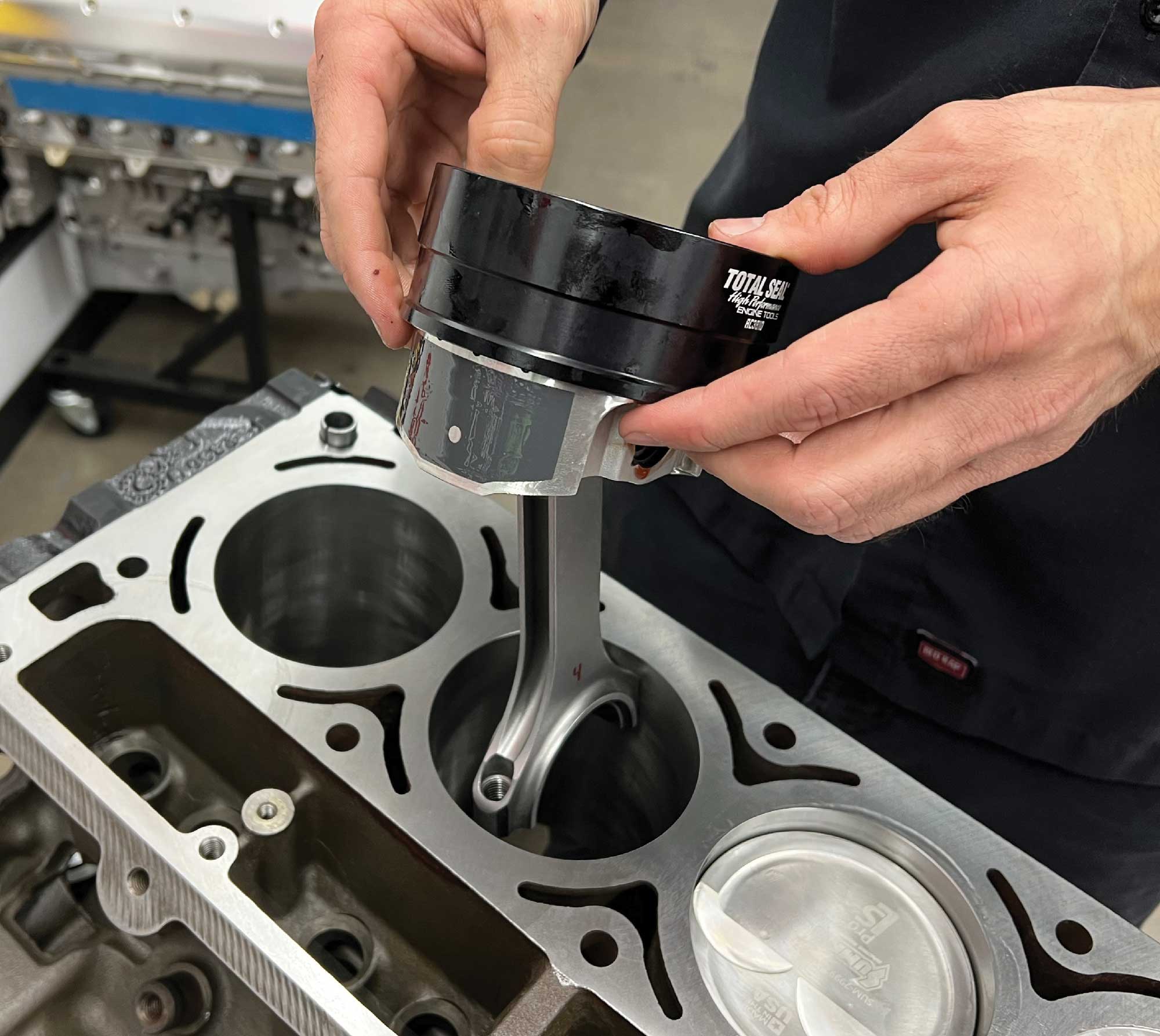
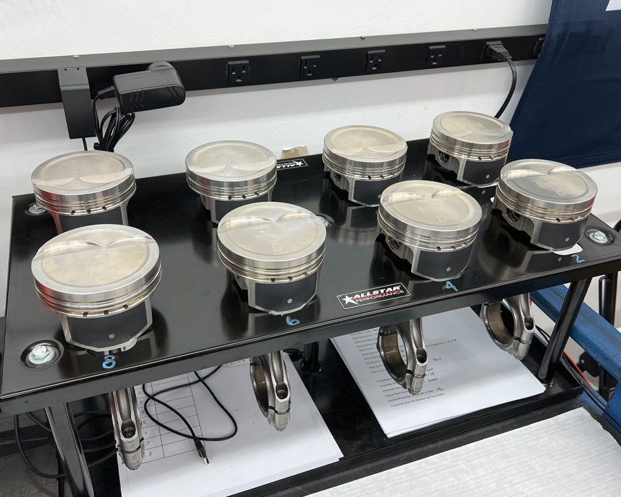
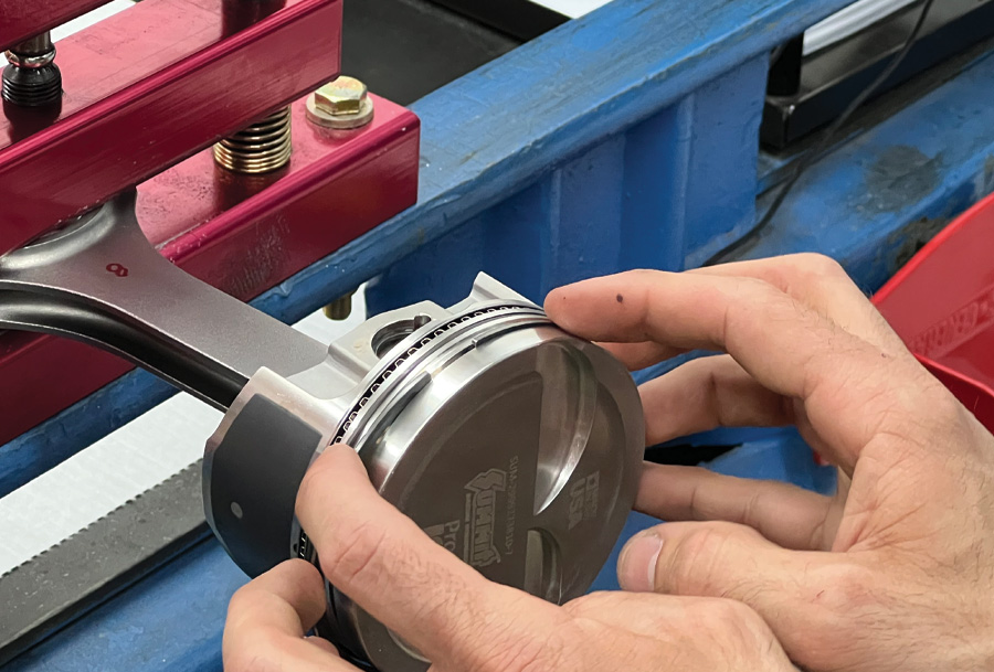
1. Kyle Martelli of American Heritage Performance (AHP) is ready to begin the assembly of the block by dropping in the first piston.
1. Kyle Martelli of American Heritage Performance (AHP) is ready to begin the assembly of the block by dropping in the first piston.
Bare Block Performance Package
 Photography by Brian Brennan Videography By Ryan Foss Productions
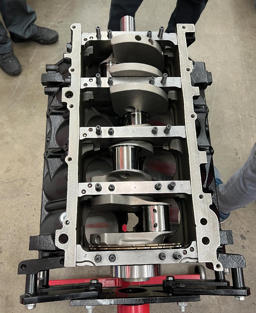
hen we concluded our Summit Racing LS (330ci) engine build last time we had the block all dialed in and the 3.622-inch stroked crankshaft in place. And while it doesn’t sound like a lot of progress, working with the team at American Heritage Performance (AHP) and their chief engine builder Kyle Martelli, we illustrated just how much prepwork is involved before engine assembly can begin. Thorough block inspection is paramount to a successful performance engine build, and Martelli’s attention to detail will no doubt show through when we put our LS engine through its paces on AHP’s dyno. But before that can happen, we need to continue with the assembly process, starting with the rotating assembly.
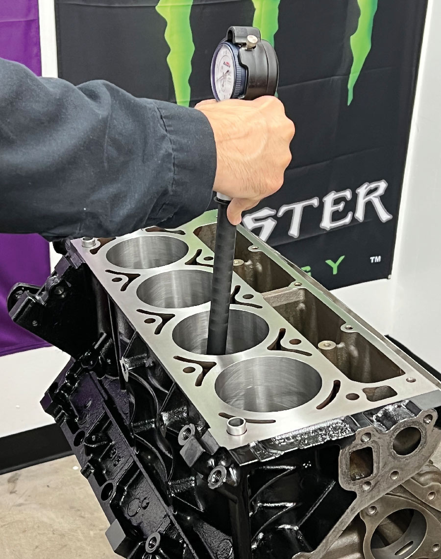
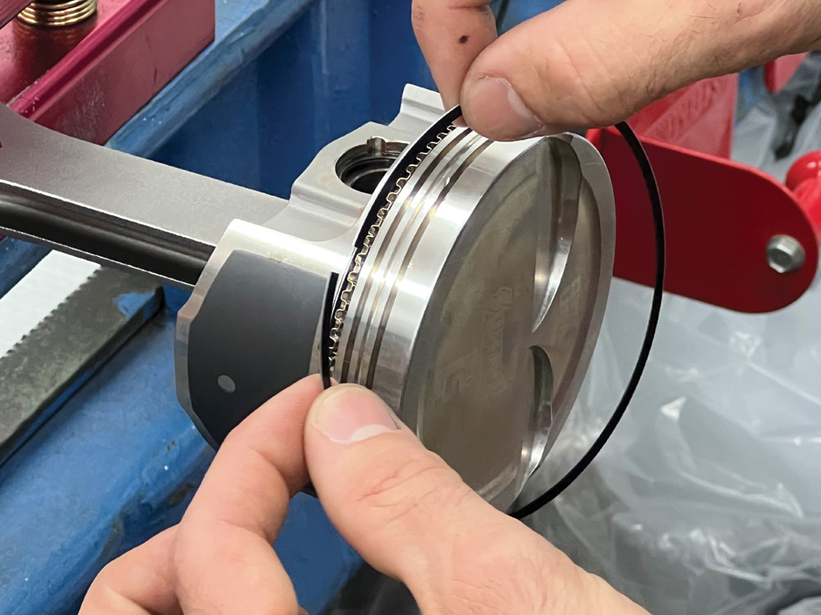
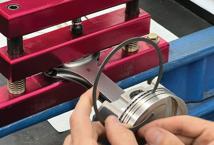
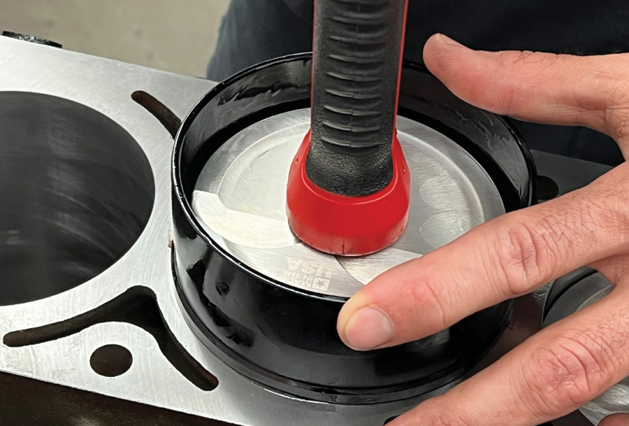
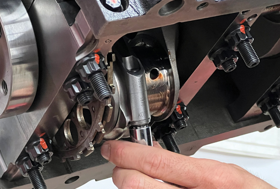
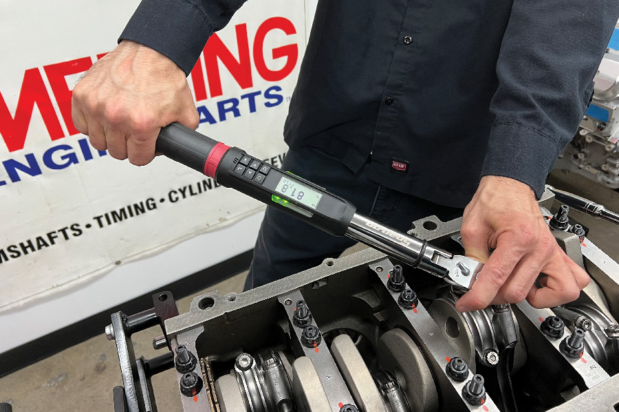
To continue with our Summit build, it should come as no surprise that we chose to use their LS Pro line of products for nearly all the moving parts in our motor. Starting with their 6.125-inch H-beam connecting rods and concluding with a set of their forged 2618 alloy pistons, the top end of our LS is a complete assembly of Summit Racing LS Pro parts. Like the crankshaft installation, Martelli inspected all the components, noted the results, and compared them to the specs provided by Summit and the bearing manufacturer. Pleased with the results, Martelli proceeded to file the ring pack to spec before assembling the piston/rod assembly. From there, using an ARP piston installation tool, Martelli dropped each slug pack into their respective cylinder, torquing every rod cap to spec via ARP 2000 rod bolts.
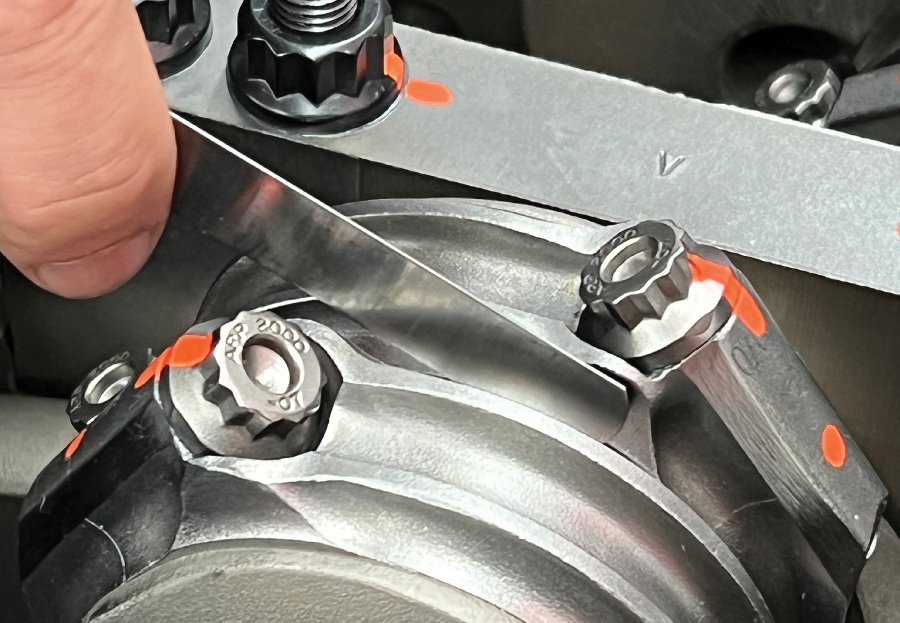
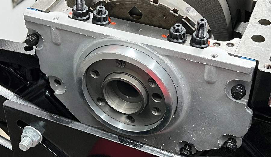
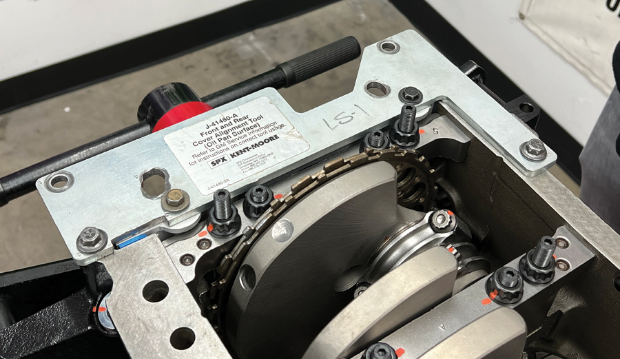
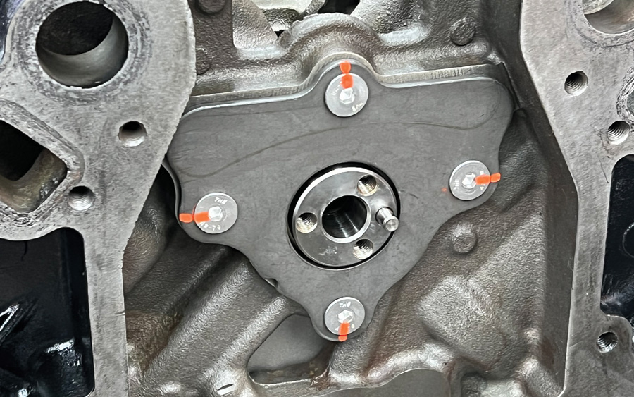
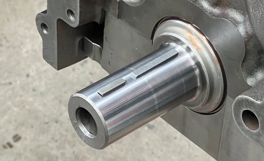
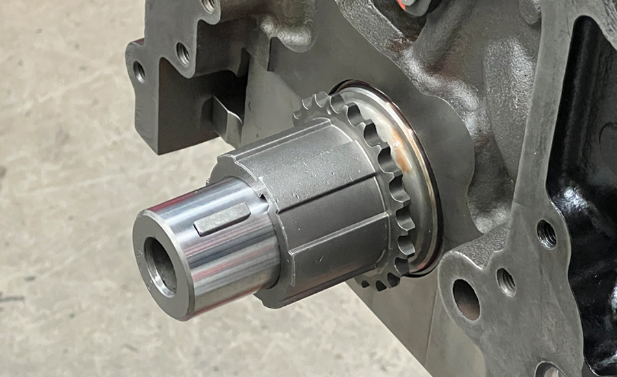
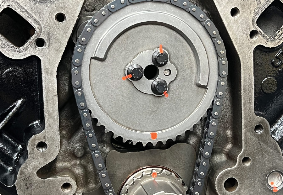
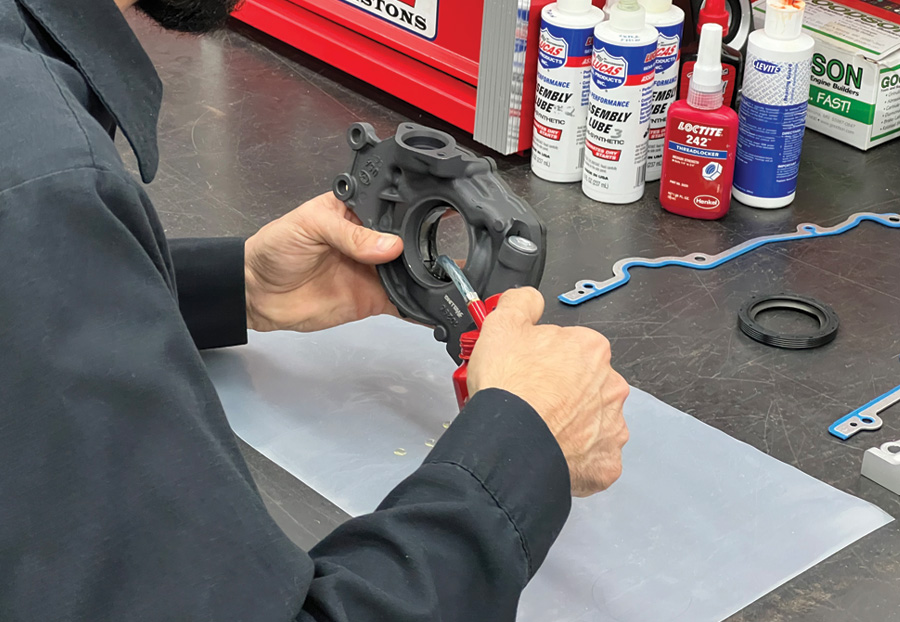
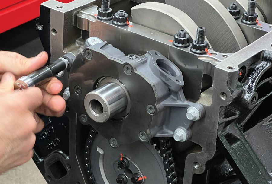
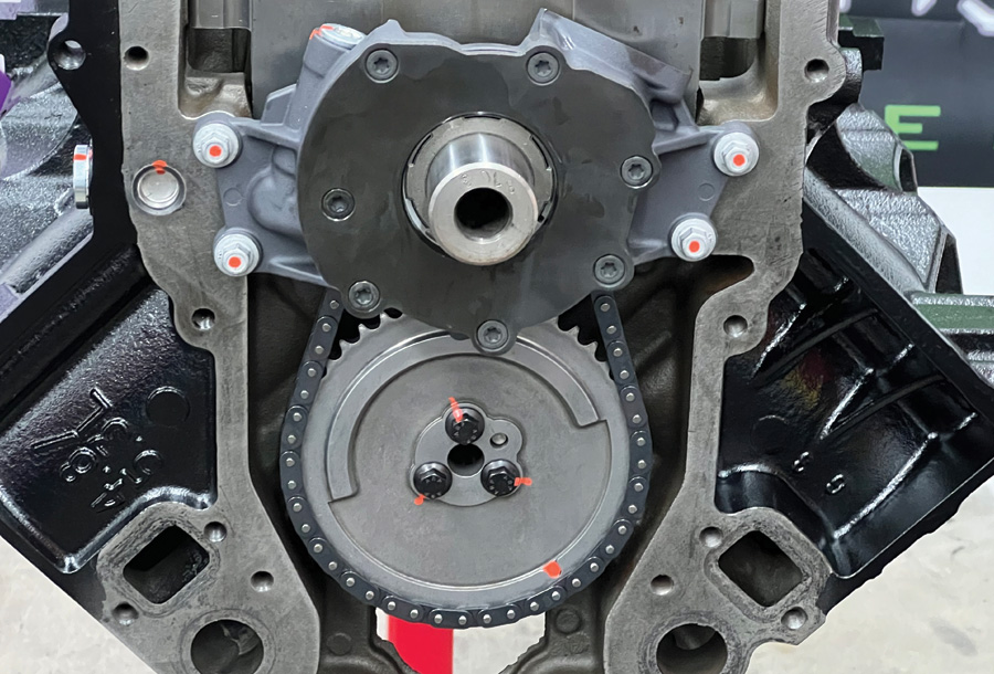
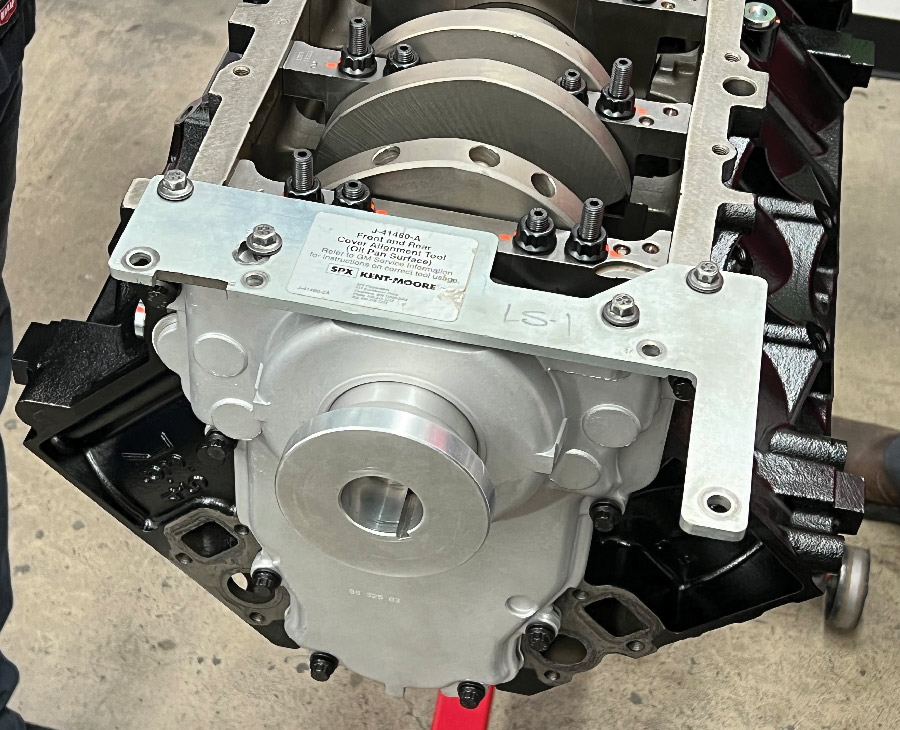
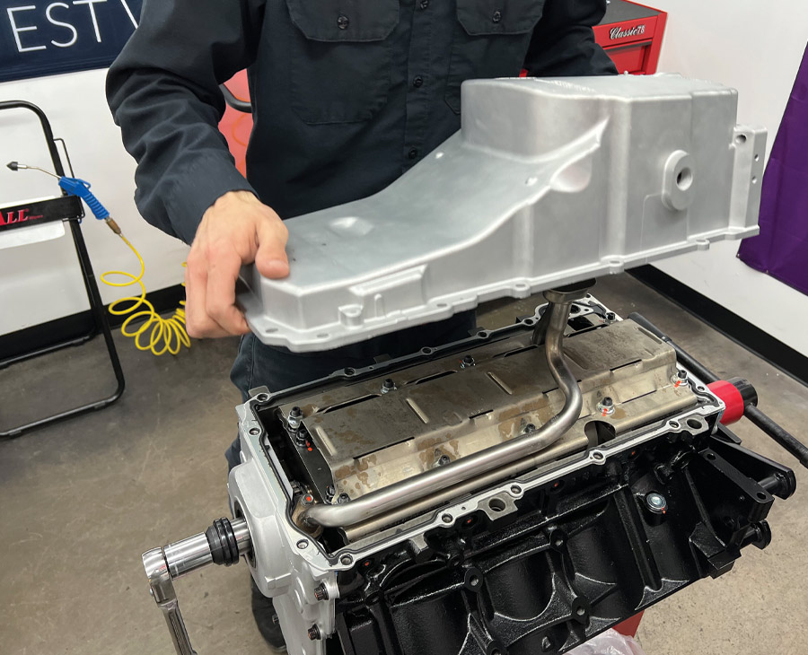
From there, Martelli installed the timing chain components and the high-volume oil pump. Front and rear covers were then installed, followed by a stock oil pan, effectively sealing up the bottom end of our short-block build.
Check out the progress this month as Martelli works his way through the bottom end and come back next time where we’ll conclude the build and put the powerplant to task on the engine dyno.
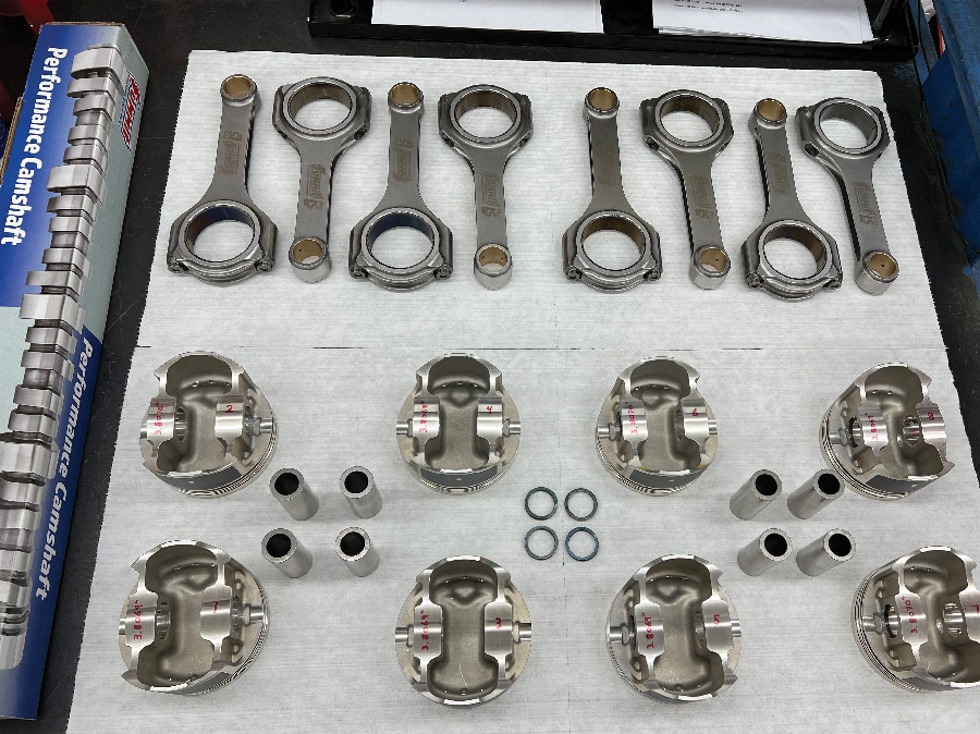
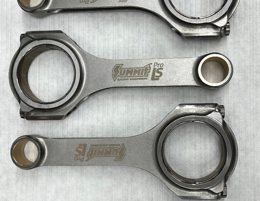
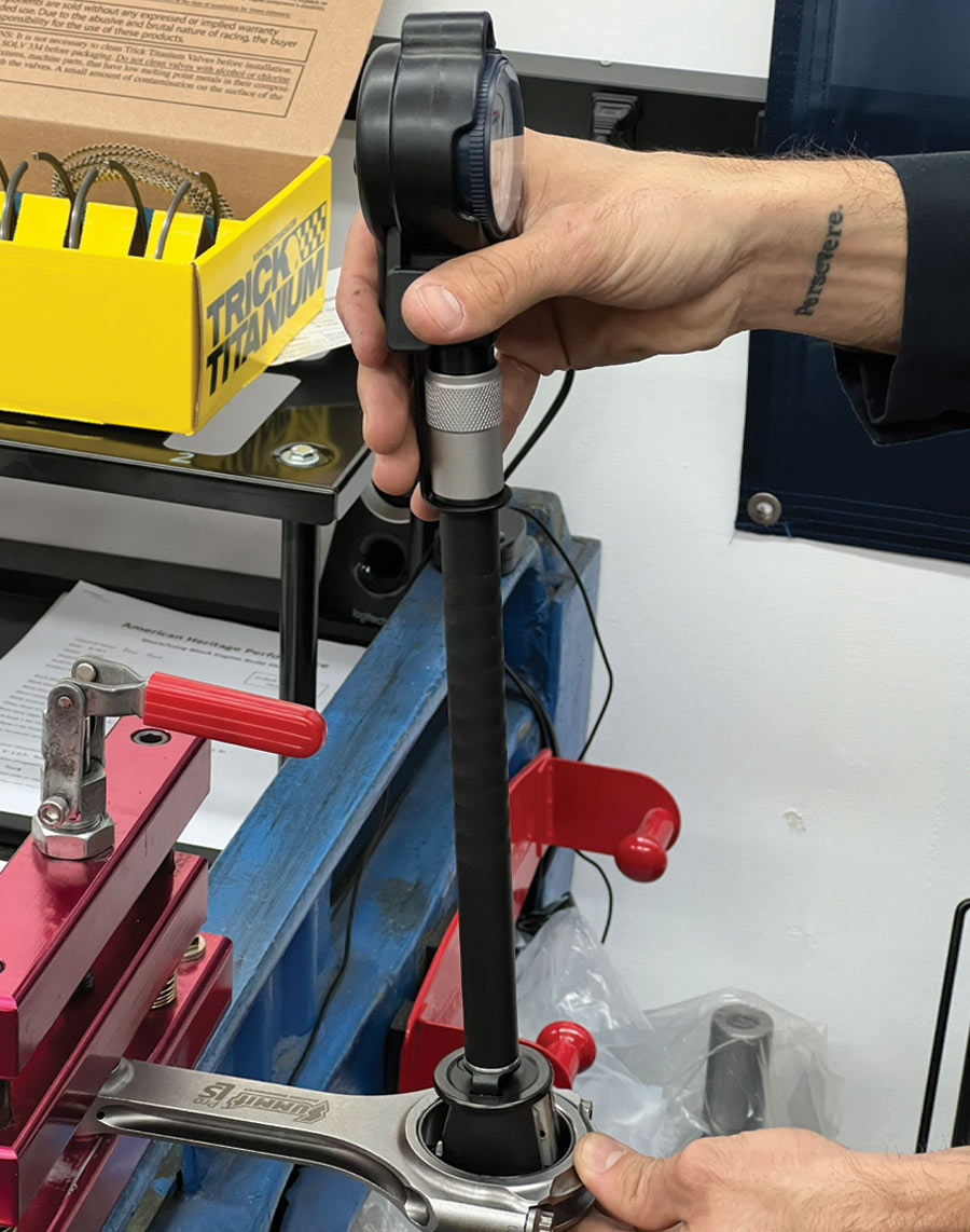
4. To mate the pistons to the crank, 4340 Forged Steel Pro LS H-beam connecting rods (PN SUM-LS6125927) from Summit will be used. Designed for up to 5,000 ft/min average piston speed, these durable rods feature a 6.125-inch length and will clear most camshafts up to a 4.250-inch stroke. Twelve-point ARP 2000 rod bolts come standard to ensure the rotating assembly remains fixed to the crankshaft.


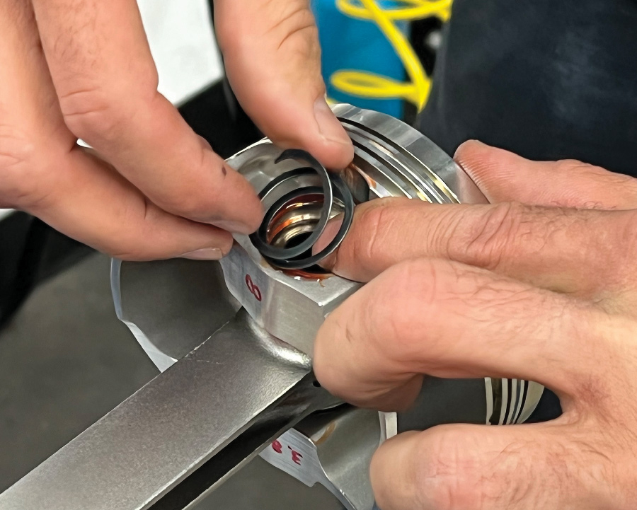
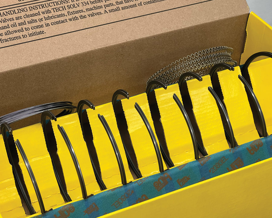
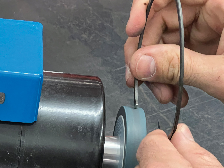
14. A set of Hastings steel performance piston rings (Summit PN SM8531035) will be used to control the oil and compression, but the two top compression rings need to be filed to fit each cylinder before assembly can begin.


VOLUME 3 • ISSUE 25 • 2022