Modern Rodding TECH
InTheGarageMedia.com
1. Willie Wray at Hot Rods by Dean sorted out all the parts required and handled the installation of a Ford Performance small-block in Brian Brennan’s Model A pickup.
 Photography by Brian Brennan
t was a great day for hot rodders when automobile manufacturers discovered there was a market for factory performance engines. It’s true that manufacturers have always seen the value of offering engines for replacement, industrial, or other purposes. That’s why even though the last Model T was produced in 1927 Ford produced the same basic Model T engine from 1908-41, which was arguably Ford’s first crate engine. But things have changed dramatically since the Model T days. Today Ford Performance offers a variety of brand-new engines in a range of performance levels; big-block, small-blocks, and modular engines are all available. To make them even more of a bargain, other than sealed race engines and those with mechanical lifter camshafts, Ford Performance crate engines come with a 24-month, 24,000-mile warranty.
Over the years there have been a number of noteworthy changes in small-block Fords. All 221-260 and early 289 engines used a five-bolt bellhousing pattern. From late 1964-on 302 blocks used the six-bolt pattern that remains in use today.
Another difference to be aware of is firing order. Ford 221, 260, and 302 engines used a sequence of 1-5-4-2-6-3-7-8. With the introduction of the H.O. 5.0L 302 the firing order was changed to 1-3-7-2-6-5-4-8, which is what Ford small-block crate engines use.
Finally, there is engine balancing. From the factory all small-block Fords were externally balanced. From introduction through 1980 all displacements used external balance weights of 28.0 oz-in. From 1981-on 302 engines (and the 255) had additional external balancing of 50 oz-in. By contrast, all current pushrod crate engines from Ford Performance are internally balanced and require a “0” balance flywheel.
Crate engines are an ideal option for powering a hot rod, a conclusion editor Brian Brennan came to when it was time to put a powerplant in his Model A pickup. To combine performance with driveability he had Hot Rods by Dean install a Ford Performance 340hp 302ci crate engine (PN M-6007-X302). This particular engine is from 2014 and has been languishing in the corner of his garage for some time (proving yet again that it takes Brennan longer to complete projects than the author). This was one of the last Ford Performance crate engines that required external balancing, other than that difference installing it is the same as current Ford Performance small-block crate offerings.
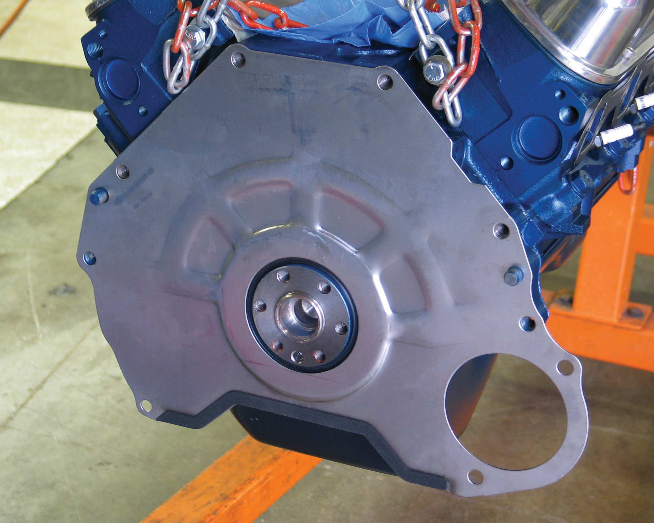
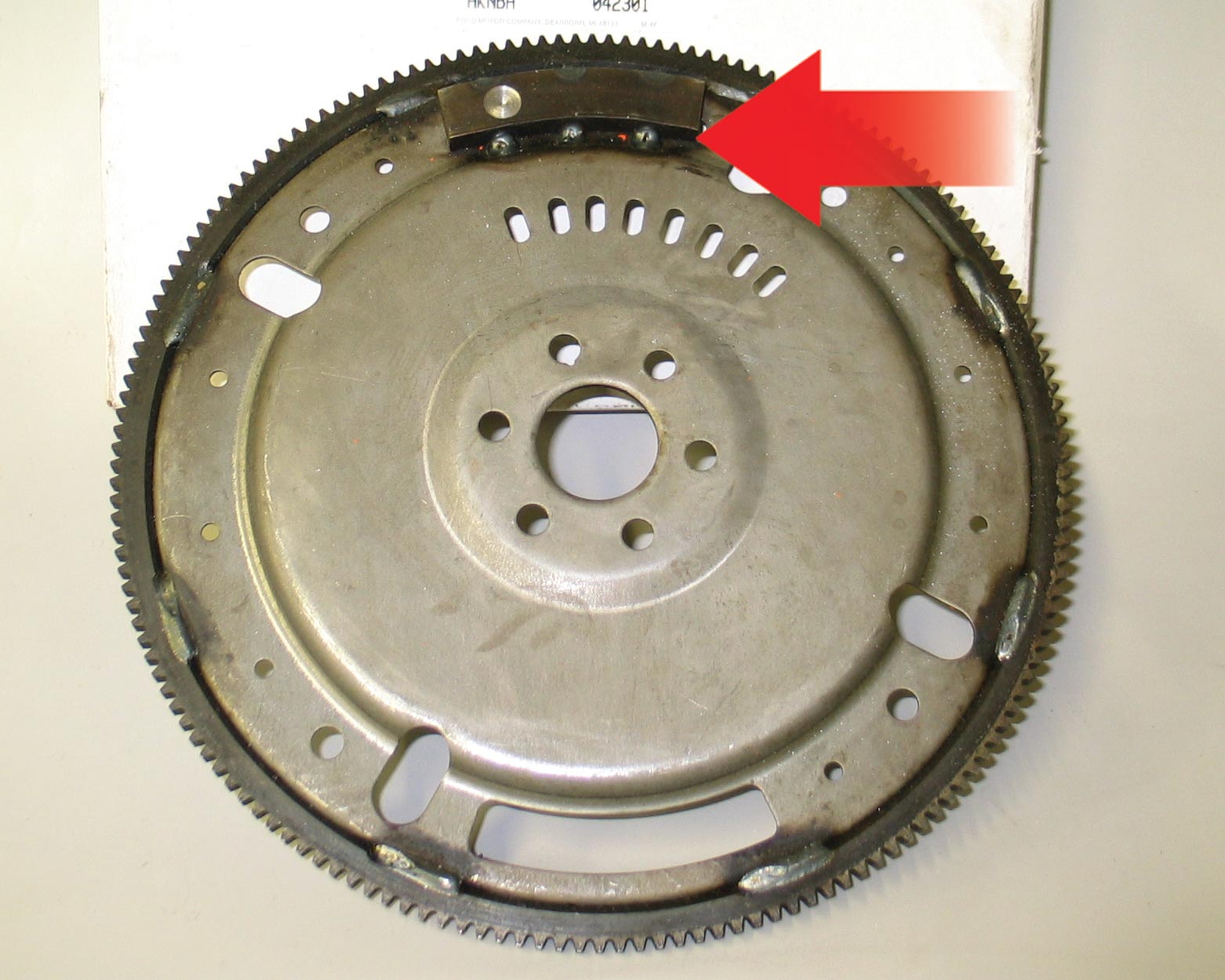
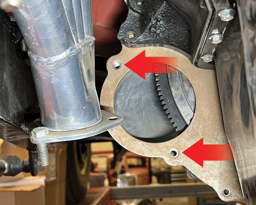
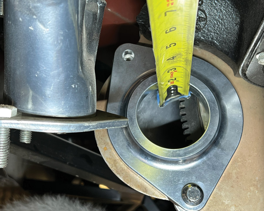
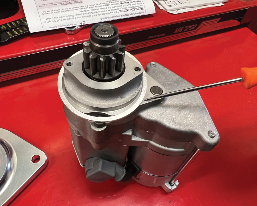
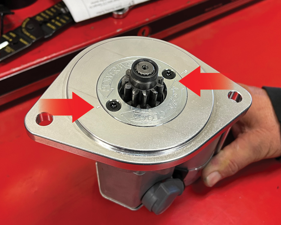
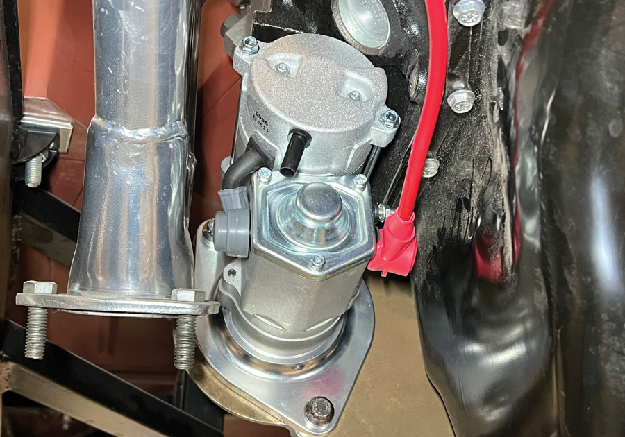
To get our crate engine assembly up and running the crew at Hot Rods by Dean had to add some ancillary components. Beginning at the back of the block the starter plate that fits between the engine and transmission was installed. Like all small-block Fords, the Powermaster starter we would be using attaches to the bellhousing, but it’s the plate sandwiched between the block and transmission that ensures the starter is located correctly in relationship to the ring gear on the flywheel or flexplate. In our case the flywheel used included a 50 oz-in weight to bring the engine into balance.
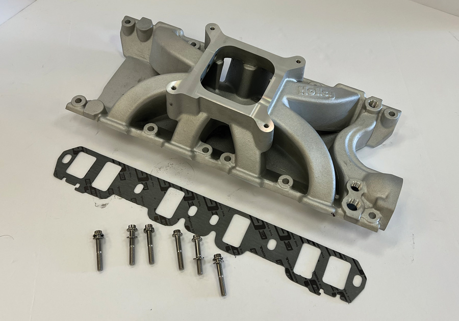
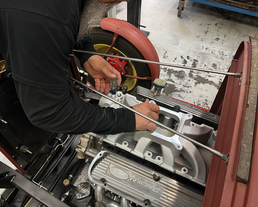
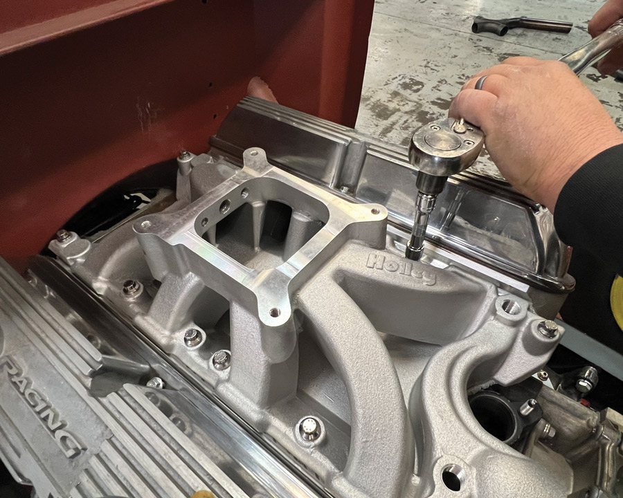
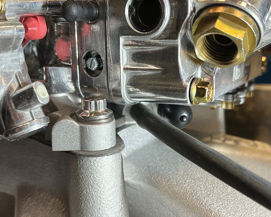
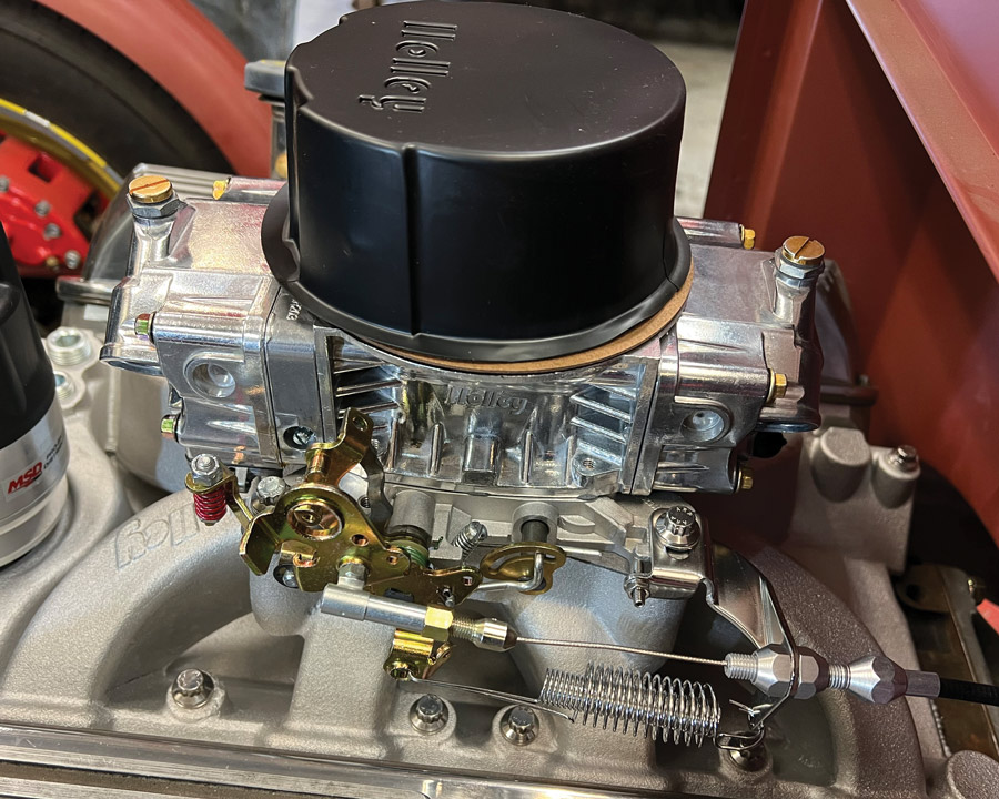
For the intake system we chose a tried-and-true combination—a Holley single-plane intake manifold (PN 300-277) topped by a Holley 600-cfm (the size recommended by Ford Performance) Street Warrior carburetor. Before securing the intake manifold, put it in place without the intake manifold gaskets. There should be at least a 0.040-inch gap at the end rails to ensure the manifold will not “bottom out” on the block. If this is allowed to happen it’s likely that oil will be sucked into the intake runners from the valley between the heads during operation.
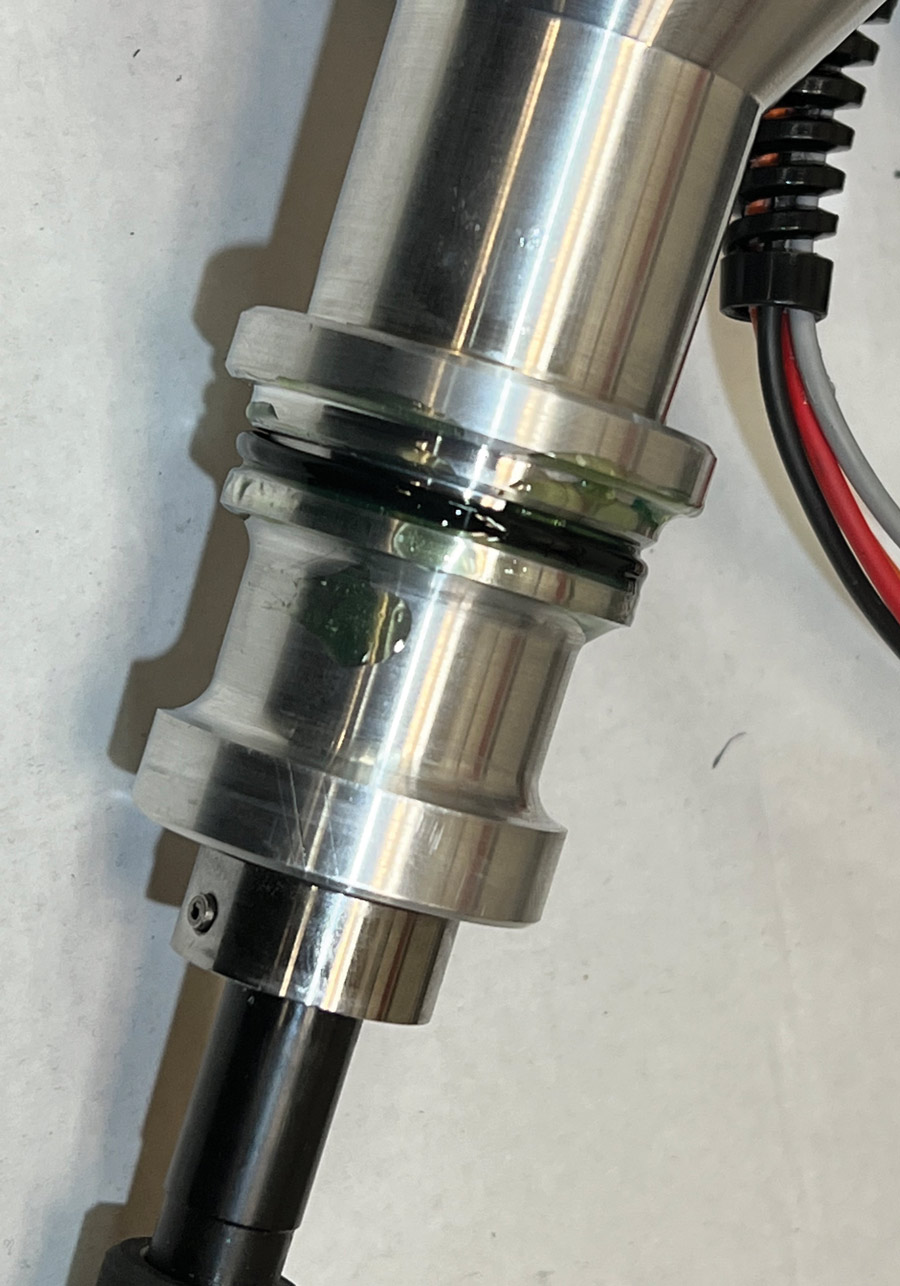
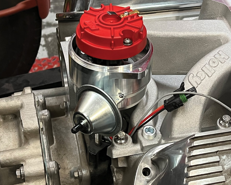
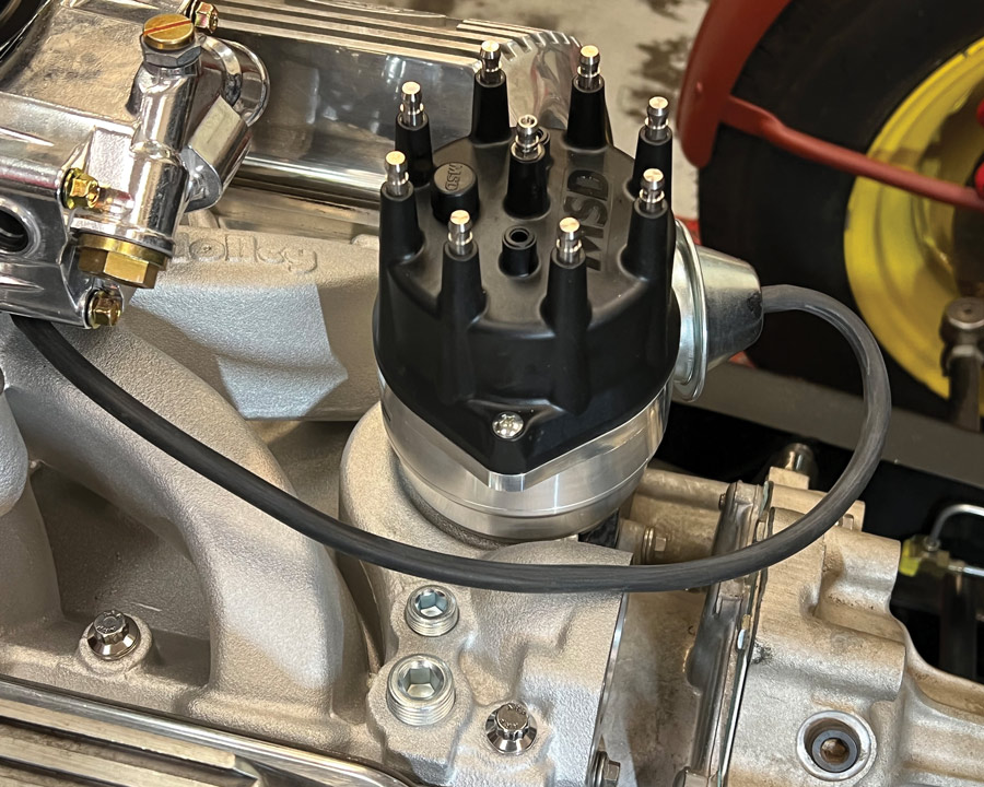
When it came to selecting a distributor, one of the considerations was the drive gear; it had to be compatible with the camshaft. Ford Performance cautions that cast-iron gears are required for castiron flat-tappet cams while steel gears are to be used with hydraulic roller cams like that in our engine. Ford Performance offers a steel distributor gear (PN M-12390-B) that can be installed on most Ford distributors, however we elected to go with MSD’s Pro- Billet Distributor (PN 83521). This distributor includes a built-in ignition module so no external control unit is required. It also comes with a melonized drive gear— which is an iron gear with a Melonite coating for use with either flat tappet or hydraulic roller camshafts.
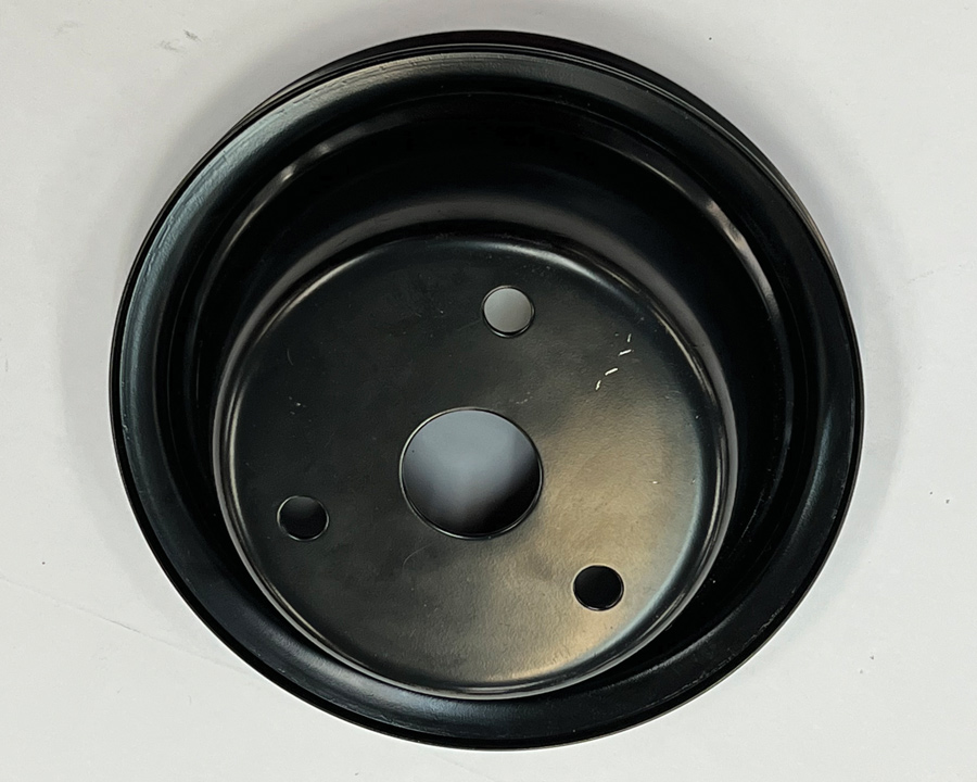
Over the years Ford has used a multitude of water pump/crankshaft pulley and water pump combinations for V-belt and serpentine drives. Early crankshaft dampers and pulleys have three attachment holes; from late 1969-on passenger car (1977-on for pickup trucks and Broncos) crankshaft dampers and pulleys have four holes. Smitty Smith at Edelbrock tells us that ’65-69 small-block water pumps (PN 8841) have the inlet on the right (passenger side) and measure 5.42 inches from the block mounting surface to the pulley mounting surface. Edelbrock pumps (PN 8843) have the inlet on the left side (driver side) and measure 5.75 inches from the block surface to the pulley flange.
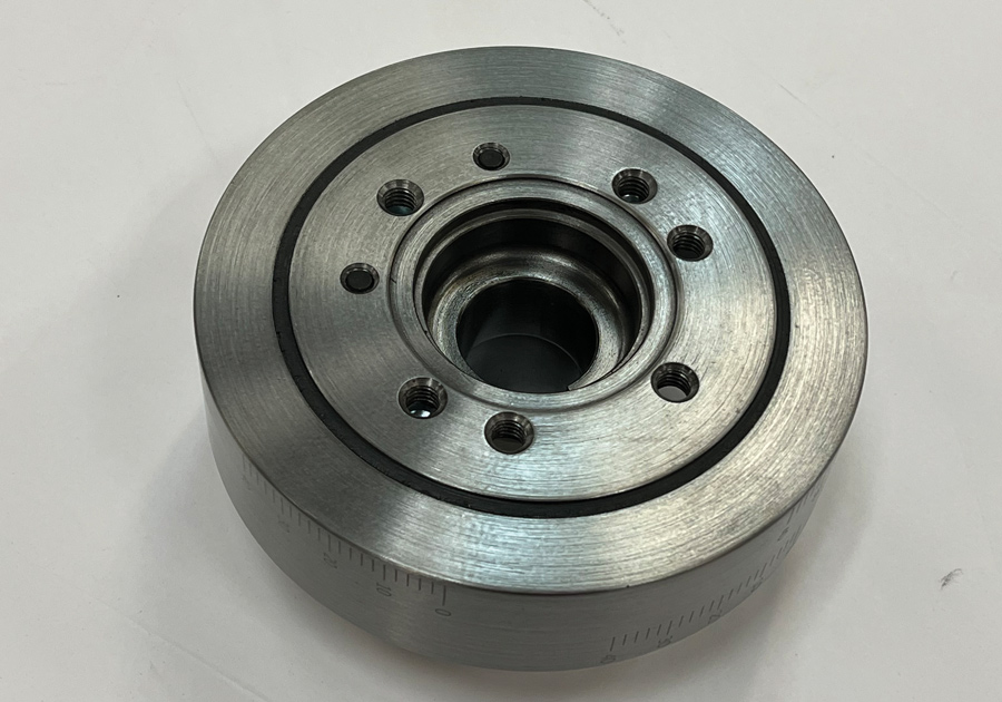
Ford Performance offers a water pump (PN M-8501-E) with a lefthand inlet that shortens the engine 1-1/2 inches and is compatible with a fourbolt crank damper, but custom pulleys are required. To keep with the minimalist theme of the truck ye ol’ editor Brennan chose to stick with steel pulleys and V-belts. To that end the factory four-bolt vibration damper was replaced with a Summit damper that has both a three- and four-bolt pattern, and an early three-bolt crankshaft pulley and an Edelbrock (PN 8843) water pump was used.
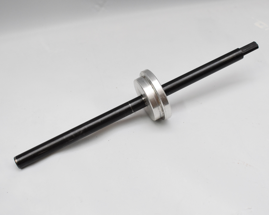
One of the most important steps in the installation procedure is properly priming the engine’s oiling system (this should never be done by cranking the engine with the starter). Ford Performance recommends filling the crankcase with 5 quarts of 10W-30 or 10W-40 oil, then installing a mechanical oil pressure gauge and removing the valve covers. Then, using the appropriate tool (Summit Racing oil pump primer, PN SUM-901011), rotate the priming tool counterclockwise using an electric drill. Once oil pressure appears on the gauge, keep priming for 1 minute, making sure oil comes up through the pushrods to the rocker arms (this may require rotating the crankshaft).
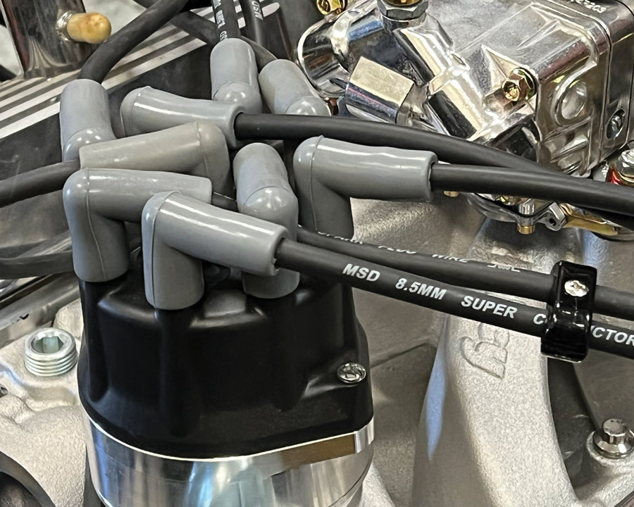
Once the engine was primed the distributor can be installed. Following Ford Performance’s instructions simplifies the process. Before removing the distributor cap, mark the number one post location on the distributor. With the cap removed, rotate the distributor shaft so the blade on the rotor is to the left of the mark, but as close to the mark as possible. As the distributor gear engages the teeth on the camshaft, the rotor will turn clockwise. It may be necessary to slightly rotate the rotor/shaft assembly, until the drive gear “drops” into position. Sometimes rotation of the oil pump driveshaft is required to allow the distributor to drop all the way. Verify the rotor blade is pointing at the #1 mark on the distributor base, loosely install the distributor hold-down clamp and bolt, then install the cap and spark plug wires in order. Once the engine is started timing should be set at 14 to 16 degrees initial, with 36 to 38 total mechanical advance (with the vacuum advance disconnected).
An Ford Performance crate engine makes sense for a variety of reasons. There are a variety of engine types and performance options to choose from, and all the components are the best current factory parts available. The cost of machining a used block, replacing all the internal components, and rebuilding heads gets expensive, and there is the time involved to make it all happen. In terms of convenience, cost, and performance, a Ford Performance crate engine is a bargain, and they come with a warranty. Who would have thought hot rodding could be this easy?



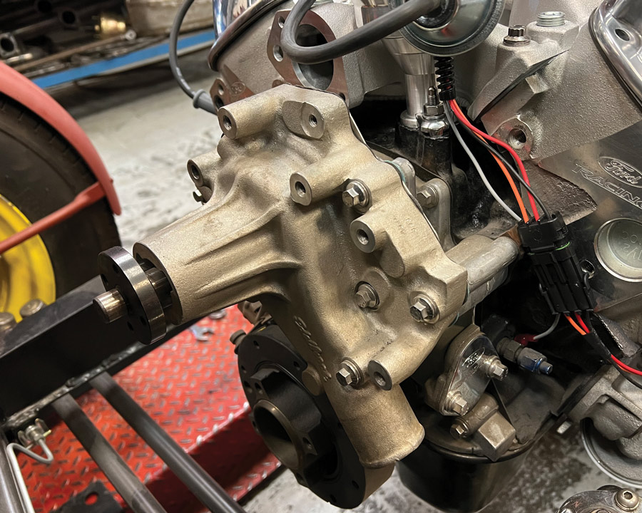


28. In some cases, the water pump pulley may require shims for proper belt alignment. This assortment came from Summit.

VOLUME 3 • ISSUE 26 • 2022