Modern Rodding Tech
InTheGarageMedia.com
Using 18-gauge sheetmetal, Tate Radford  fashioned the upper portion of a replacement  firewall for Colin and Sue Radford’s ’57 Ford wagon.

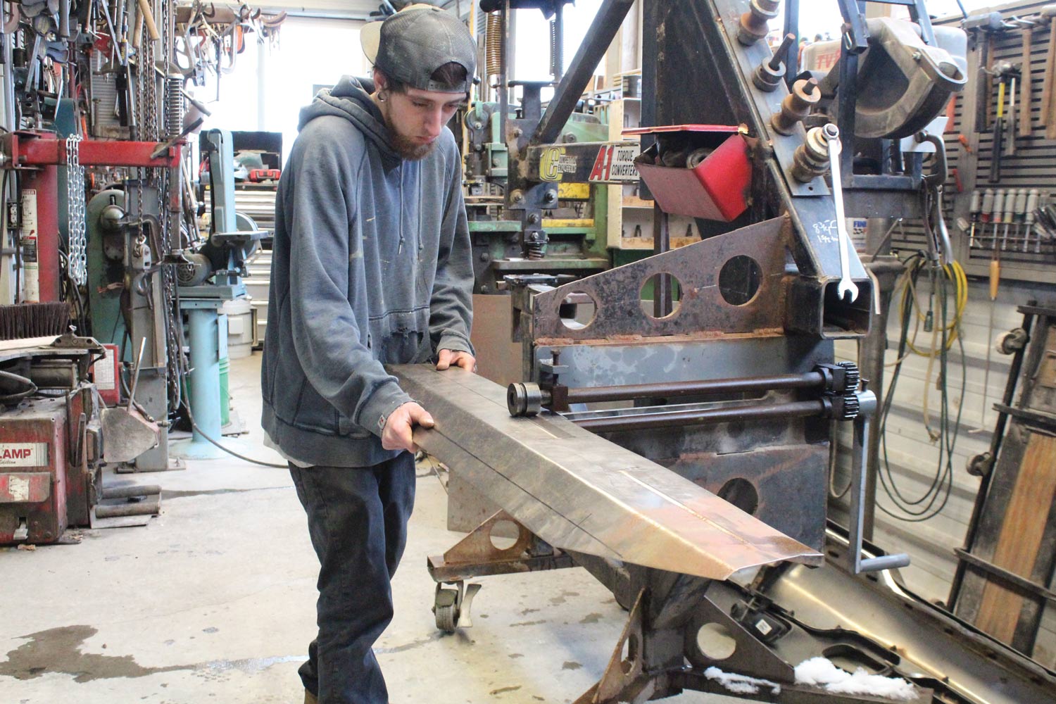
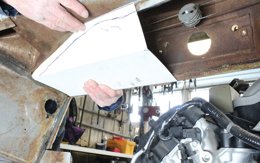
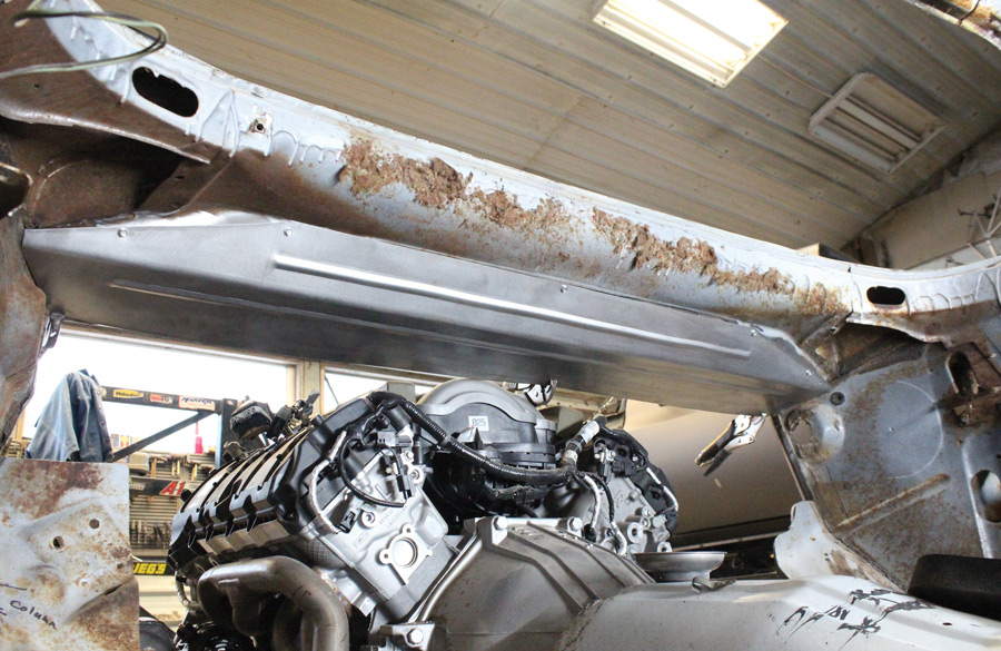
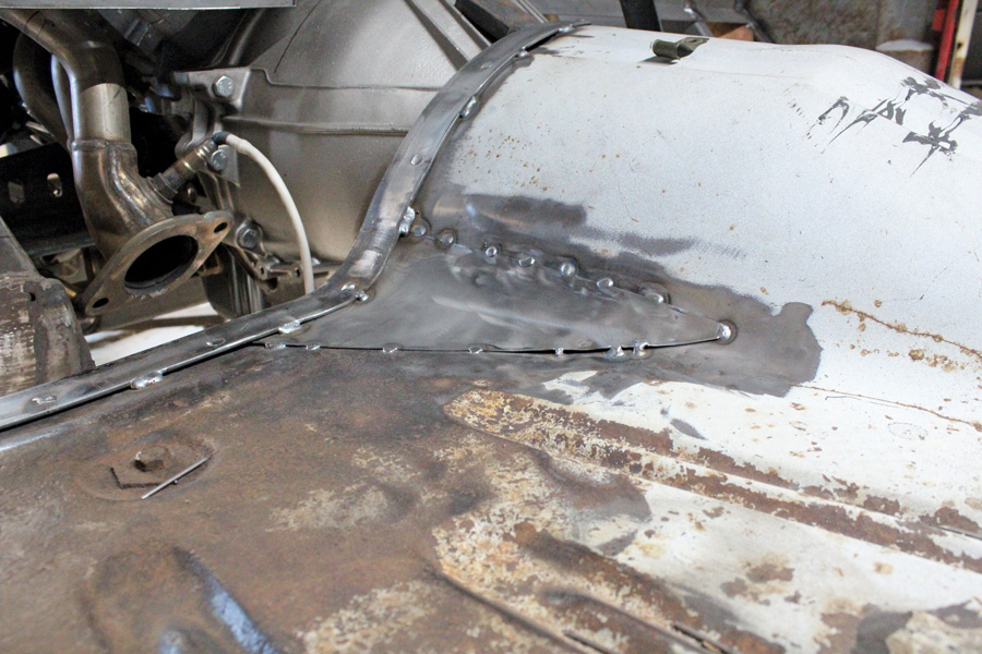
1. Using 18-gauge sheetmetal, Tate Radford fashioned the upper portion of a replacement firewall for Colin and Sue Radford’s ’57 Ford wagon.

Ranch Wagon Redo
Part III: Fabricating a Firewall and Installing a Flaming River Column
By Ron Ceridono Photography by Tate Radford & Colin Radford
W

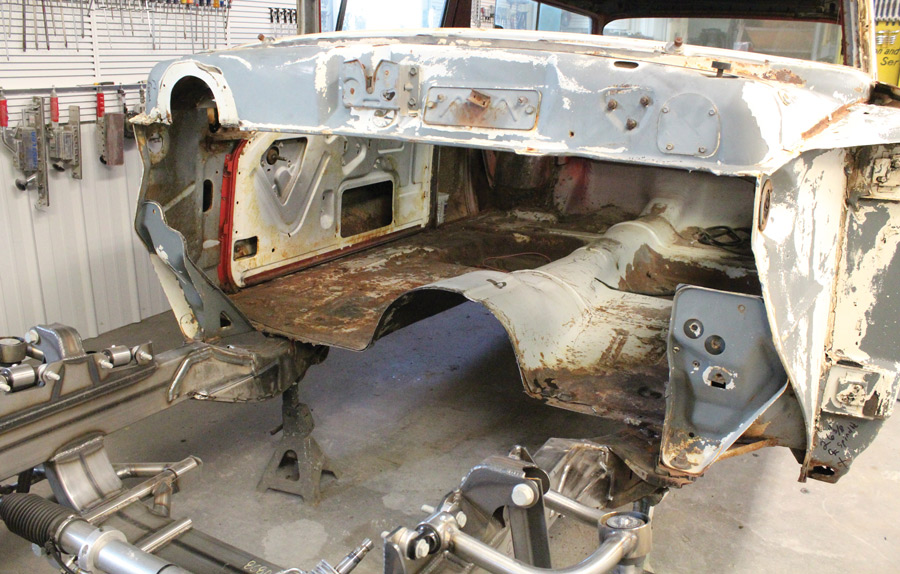
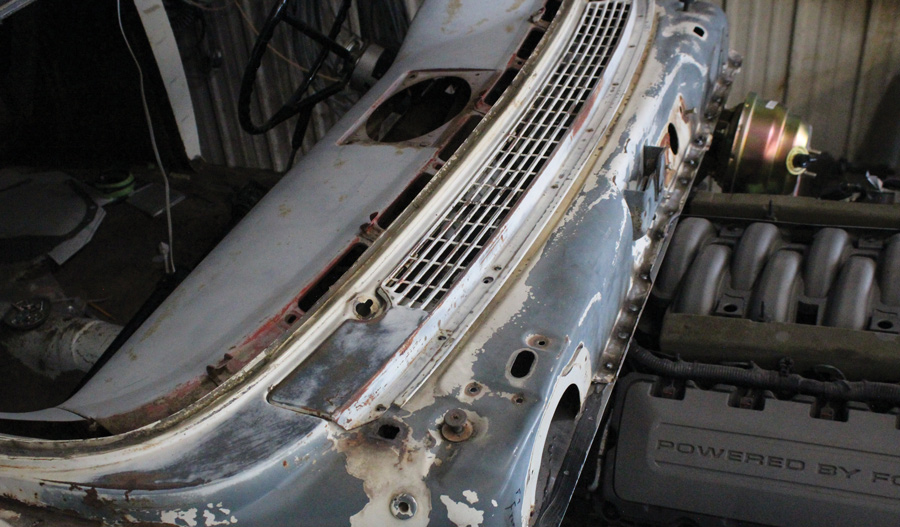
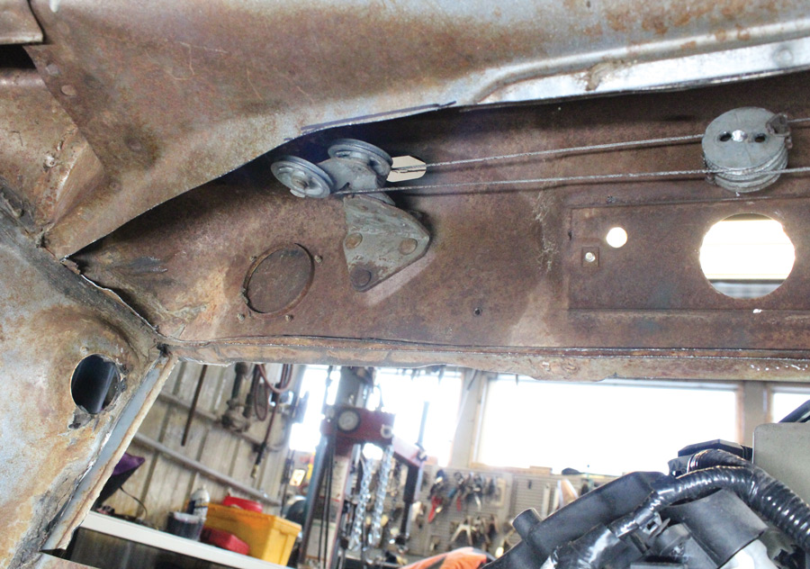
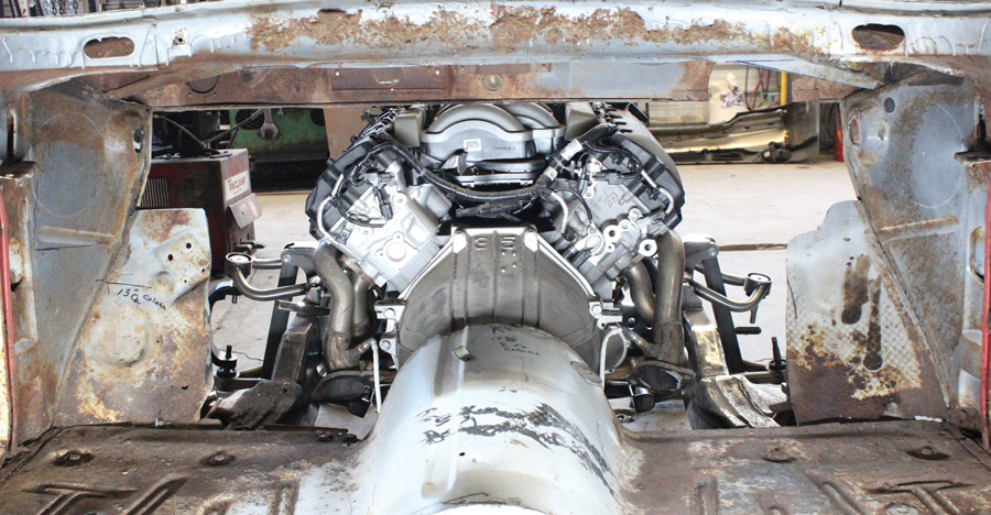
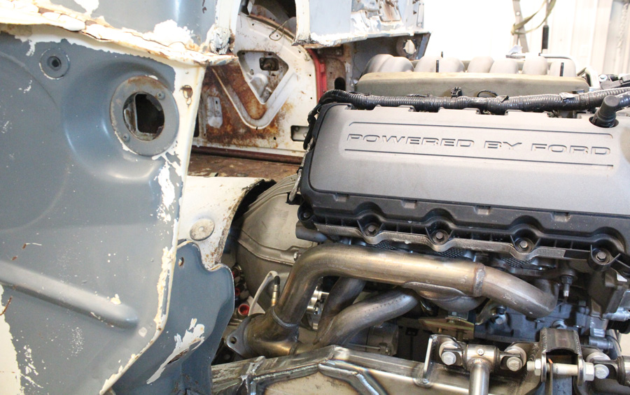
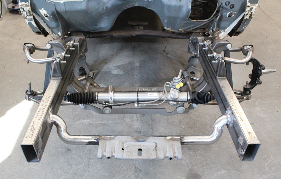
e’ve been following along as Colin and Sue Radford’s ’57 Ford Del Rio Ranch Wagon has been undergoing the transformation from a Leave It To Beaver–era grocery-getter to a contemporary hot rod. With the capable, helping hands of grandsons Tate and Caden, the original front suspension was tossed out and replaced with an Art Morrison Enterprises (AME) Bikini Clip. The Y-block was set aside to make room for a Ford Performance Coyote V-8, which brings us to where we are now: making a little bit more room for the replacement powerplant with a new firewall and installing the Flaming River steering components.

During mock-up it was determined that the best position for the engine would require moving the firewall back roughly 2 inches. In this particular case, the Ford’s firewall had an issue that needed to be addressed anyway. The plenum in front of the windshield that fed fresh air to the factory heating system had some rust issues. As future plans call for a Vintage Air climate-control system that does not rely on outside air, the decision was made to cut down the size of the plenum, killing two birds with one stone—the engine could be tucked under the cowl and the difficult-to-repair rusted areas were eliminated.

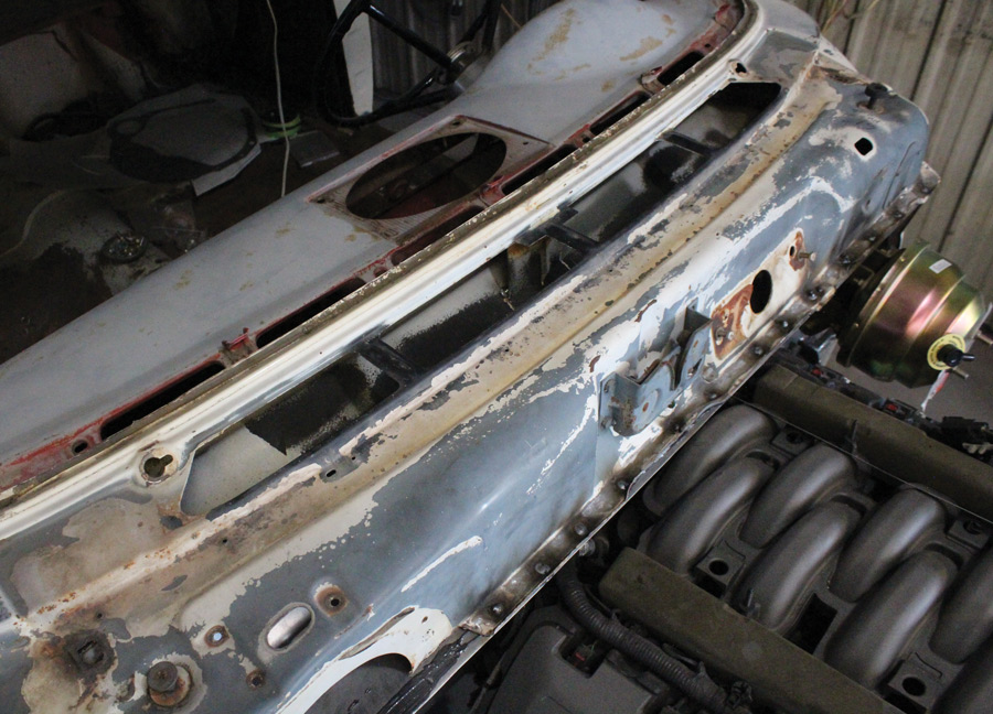
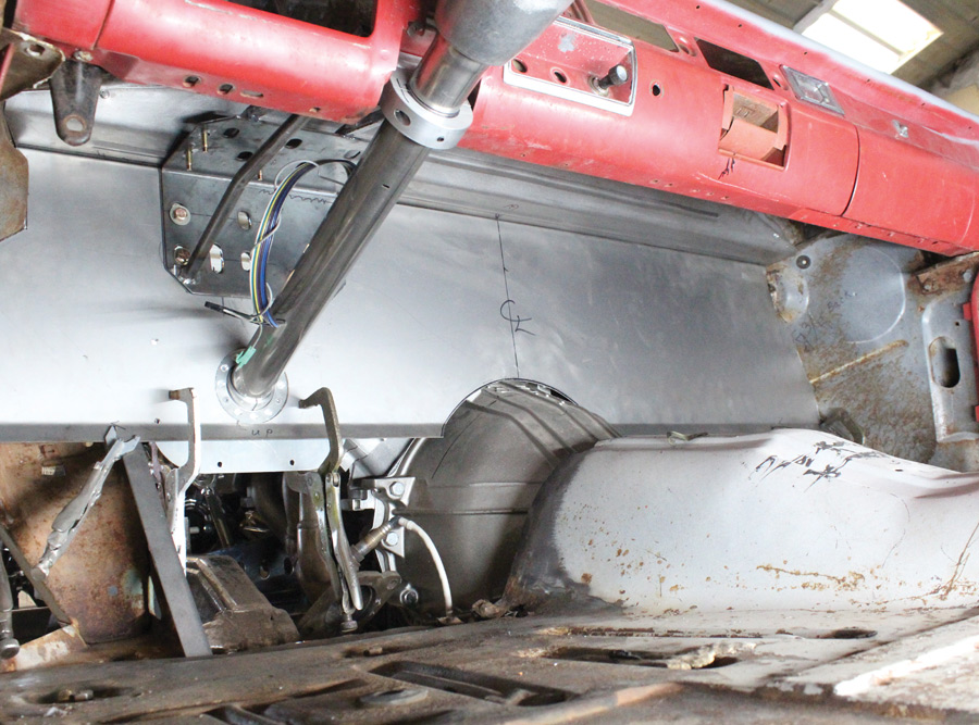
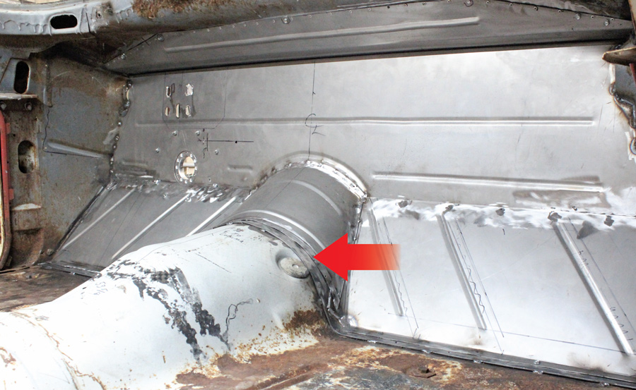
With the heater plenum issue resolved, a new flat firewall was fabricated. Thanks to the generous dimensions of the stock Ford transmission tunnel no modifications to the floor above the Gearstar transmission case were required, although new toeboards and the bellhousing tunnel were needed.

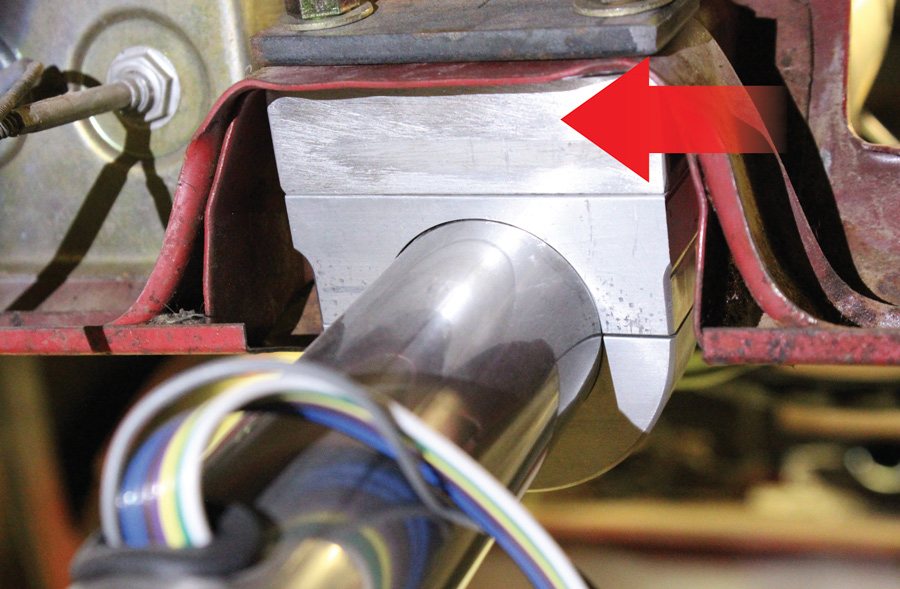
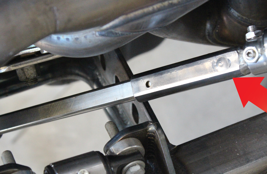
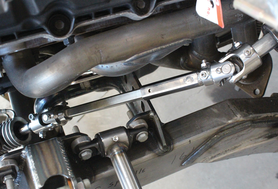
Despite the size of the Coyote V-8, routing the steering shaft from the Flaming River tilt column to the rack-and-pinion was a straight shot and would only require two universal joints. To connect those U-joints a conventional, solid, 3/4-inch Flaming River double D shaft could have been used, however, it was decided to incorporate a slip shaft to accommodate any movement between the body-mounted steering column and the chassis-mounted rack-and-pinion. This was accomplished by sliding a section of 1-inch double D tube over a short piece of 3/4-inch double D shaft and welding them together (the weld just keeps them from slipping apart). That section of the steering shaft is attached to the U-joint on the steering column. On the lower end of the assembly a length of solid, 3/4 double D shaft attaches to the steering gear with a U-joint and fits well into the 1-inch double D. The result is a slip shaft that will absorb any movement between the body and frame and can’t come apart.

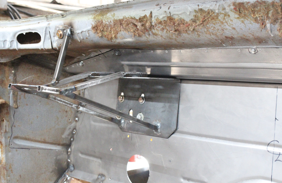
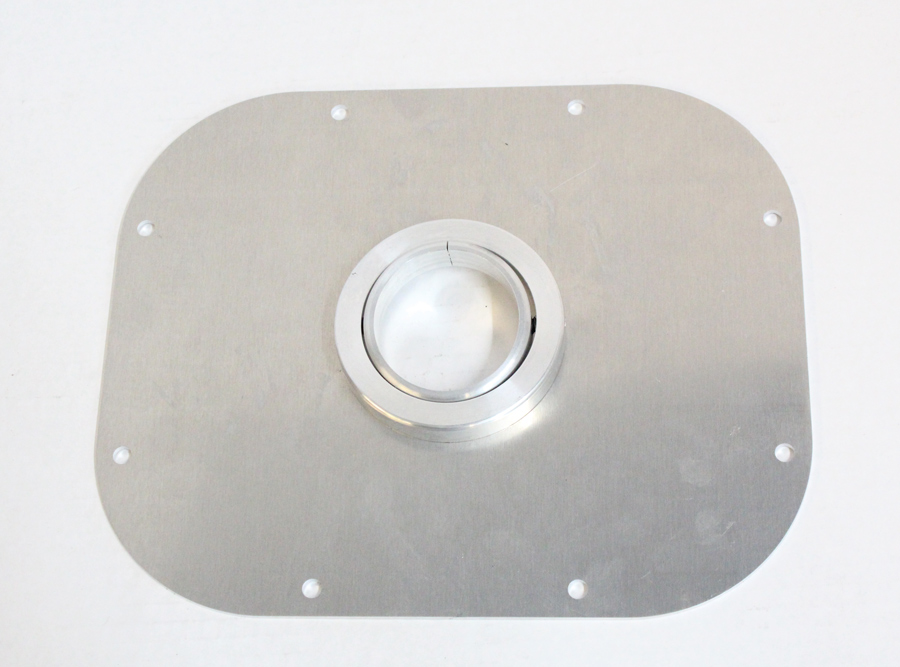
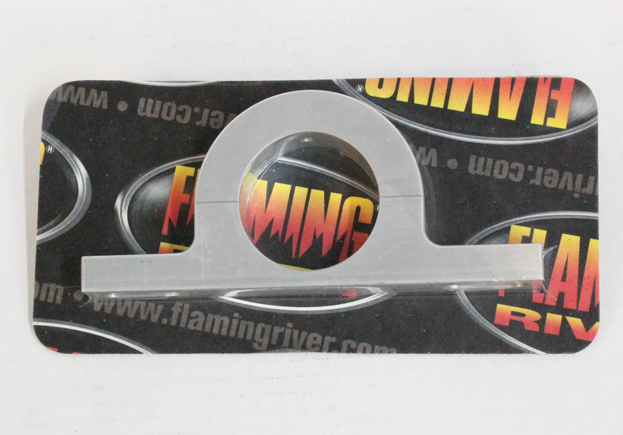
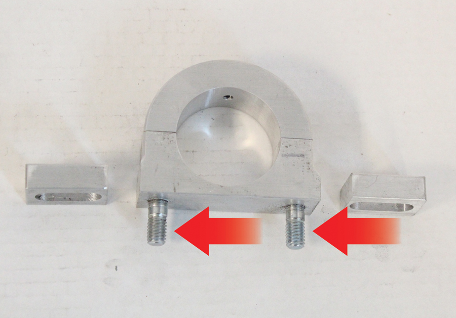
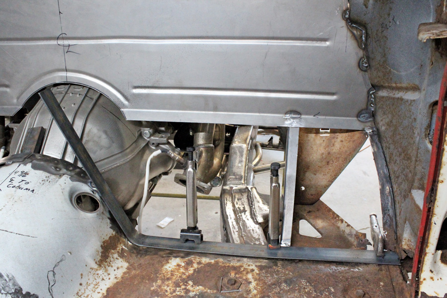
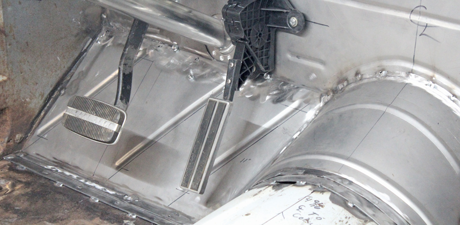
To mount the steering column at the bottom a Flaming River “blank slate” swivel mount (PN FR20101BLS) was used (this universal floor mount is designed to be used in a street rod build that will include a new firewall). At the upper end a Flaming River factory-style 2-inch dash mount (PN FR20114PL) was modified to fit the stock Ford dash bracket. For rigidity, a support that ties the steering column, brake pedal, and master cylinder/booster assembly was fabricated from flat stock and tubing.

Building the ’57 Ford Del Rio has been a real family affair for the Radfords, which is fitting considering station wagons were once the ultimate utilitarian family vehicle. Who knows, cool as this one is turning out they may be again.
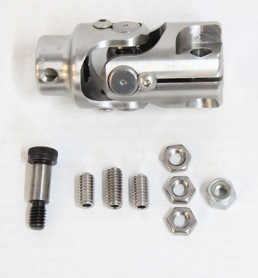
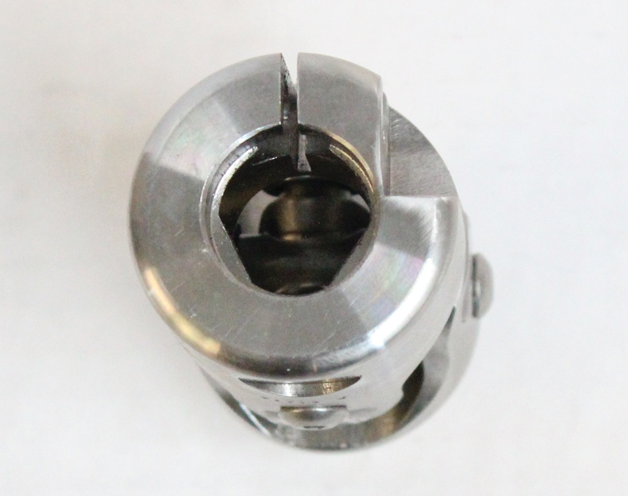
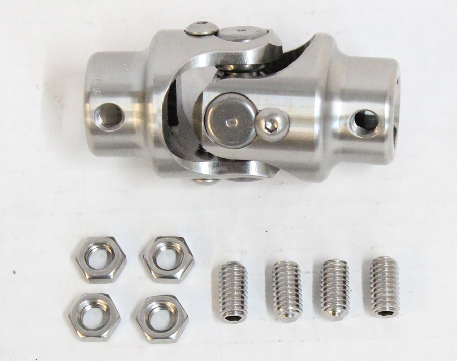
 The lower portion of the Ford’s firewall cut at the seam where it joined the cowl and was removed.
2. The lower portion of the Ford’s firewall cut at the seam where it joined the cowl and was removed.
 The vent panel in front of the windshield provided fresh air to the factory heating system. It also concealed the windshield wiper mechanism.
3. The vent panel in front of the windshield provided fresh air to the factory heating system. It also concealed the windshield wiper mechanism.
With the vent panel removed, rust holes were discovered in the bottom of the plenum where they would be difficult to repair.
4. With the vent panel removed, rust holes were discovered in the bottom of the plenum where they would be difficult to repair.
Rather than repair the bottom of the plenum it was removed. Note the cables that operated the factory windshield wipers—not one of Ford’s better ideas.
5. Rather than repair the bottom of the plenum it was removed. Note the cables that operated the factory windshield wipers—not one of Ford’s better ideas.
To accommodate the Coyote V-8 the firewall, toeboards, and front of the transmission tunnel were removed. The good news was the factory tubular headers fit without modification.
6. To accommodate the Coyote V-8 the firewall, toeboards, and front of the transmission tunnel were removed. The good news was the factory tubular headers fit without modification.
The engine sits back roughly 2 inches from the seam where the original firewall joined the cowl. Despite the recess all the engine components, such as the intake manifold and cam covers, can be removed with the engine in place.
7. The engine sits back roughly 2 inches from the seam where the original firewall joined the cowl. Despite the recess all the engine components, such as the intake manifold and cam covers, can be removed with the engine in place.
With the bottom of the heater plenum removed a paper pattern was made to form the replacement. The large hole in the cowl is where the windshield wiper motor mounts from the engine compartment side.
8. With the bottom of the heater plenum removed a paper pattern was made to form the replacement. The large hole in the cowl is where the windshield wiper motor mounts from the engine compartment side.
The replacement sheetmetal was temporarily held in place with sheetmetal screws. Ultimately it would be secured with rivets and panel-bonding adhesive.
9. The replacement sheetmetal was temporarily held in place with sheetmetal screws. Ultimately it would be secured with rivets and panel-bonding adhesive.
For strength a fabricated brace attaches to the firewall with the bolts for the brake booster, a bolt in the cowl, and it will be attached to the steering column mount.
10. For strength a fabricated brace attaches to the firewall with the bolts for the brake booster, a bolt in the cowl, and it will be attached to the steering column mount.
Securing the bottom of the steering column is a mounting plate with a swivel socket from Flaming River.
11. Securing the bottom of the steering column is a mounting plate with a swivel socket from Flaming River.
Here the flat lower firewall section has been installed, the brace and steering column are in place. Note how the socket in the Flaming River mounting plate swivels to accommodate the angle of the column.
12. Here the flat lower firewall section has been installed, the brace and steering column are in place. Note how the socket in the Flaming River mounting plate swivels to accommodate the angle of the column.
At the top of the Flaming River steering column a Flaming River 2-inch dash mount was used, however it was modified to fit.
13. At the top of the Flaming River steering column a Flaming River 2-inch dash mount was used, however it was modified to fit.
Due to the steering column recess in the Ford’s dashboard, the Flaming River dash mount was modified by cutting off the mounting ears. Then two holes were drilled and tapped for mounting studs <i>(arrows)</i>.
14. Due to the steering column recess in the Ford’s dashboard, the Flaming River dash mount was modified by cutting off the mounting ears. Then two holes were drilled and tapped for mounting studs (arrows).
The modified column mount was used with a spacer  (arrow) that then fit in the factory dashboard recess perfectly. The modified mount will be hidden behind the original Ford sheetmetal cover.
15. The modified column mount was used with a spacer (arrow) that then fit in the factory dashboard recess perfectly. The modified mount will be hidden behind the original Ford sheetmetal cover.
Our AME Bikini Clip was equipped with a Flaming River ’79-93 Mustang-type power rack-and-pinion steering gear (PN FR40002PLN).
16. Our AME Bikini Clip was equipped with a Flaming River ’79-93 Mustang-type power rack-and-pinion steering gear (PN FR40002PLN).
A unique feature of the Flaming River rack is the triangular shape of the sector shaft; it requires a Flaming River U-joint FR Power x 3/4-inch DD (PN FR2589P).
17. A unique feature of the Flaming River rack is the triangular shape of the sector shaft; it requires a Flaming River U-joint FR Power x 3/4-inch DD (PN FR2589P).
Not only is the shape of the required U-joint unique but there are also no splines as it uses a bolt to clamp onto the sector shaft—note the slot that allows that to happen.
18. Not only is the shape of the required U-joint unique but there are also no splines as it uses a bolt to clamp onto the sector shaft—note the slot that allows that to happen.
To connect the steering shaft to the Flaming River column a 1-inch double D x 3/4-inch double D U-joint was used  (PN 2517 DD).
19. To connect the steering shaft to the Flaming River column a 1-inch double D x 3/4-inch double D U-joint was used
(PN 2517 DD).
To make a slip shaft Colin Radford used a combination of 3/4-inch double D solid shaft and 1-inch double D tube. Note the welds on the upper shaft (arrows). The hole is for a zerk fitting that will be added.
20. To make a slip shaft Colin Radford used a combination of 3/4-inch double D solid shaft and 1-inch double D tube. Note the welds on the upper shaft (arrows). The hole is for a zerk fitting that will be added.
The lower solid shaft fits far enough into the 1-inch tube that it can never come apart while it is free to move in and out to absorb any movement between the body and chassis.
21. The lower solid shaft fits far enough into the 1-inch tube that it can never come apart while it is free to move in and out to absorb any movement between the body and chassis.
A minor modification was necessary to the floorpan to provide room for the transmission’s shift linkage. Other than that, no other transmission tunnel modifications were required.
22. A minor modification was necessary to the floorpan to provide room for the transmission’s shift linkage. Other than that, no other transmission tunnel modifications were required.
With the upper portion of the firewall in place, attention was turned to the toeboards. Note the flat steel strap that’s being clamped in place—it will serve to reinforce the floor.
23. With the upper portion of the firewall in place, attention was turned to the toeboards. Note the flat steel strap that’s being clamped in place—it will serve to reinforce the floor.
Colin used a slip roll to form the section of the floor that would cover the bellhousing.
24. Colin used a slip roll to form the section of the floor that would cover the bellhousing.
 Here the firewall is completed. Note the round plug in the trans tunnel (arrow). That’s where the transmission fluid was checked back in the day—not particularly convenient.
25. Here the firewall is completed. Note the round plug in the trans tunnel (arrow). That’s where the transmission fluid was checked back in the day—not particularly convenient.
A brake pedal of undetermined origin was equipped with a Ford Swift Sure Power Brake pedal pad and the electronic throttle has a cable-style pedal grafted on.
26. A brake pedal of undetermined origin was equipped with a Ford Swift Sure Power Brake pedal pad and the electronic throttle has a cable-style pedal grafted on.
Flaming River Industries
(806) 648-8022
flamingriver.com
Ford Performance
(800) 367-3788
performanceparts.ford.com
Radford Automotive
(208) 745-1350
Modern Rodding
VOLUME 3 • ISSUE 20 • 2022