Modern Rodding Tech
InTheGarageMedia.com
Early Ford Kingpins, Rekindled
Replacing Bushed Bushings With Much-Needed Needle Bearings
By Ryan Manson Photography by the Author
A

tight frontend can make all the difference between an enjoyable early Ford and a downright rotten roach of a hot rod. A car that wanders around the lane, is hard to steer and control, or clunks, clangs, and creaks while going down the road is not only uncomfortable, it’s dangerous. Thankfully, early Fords are easy to work on, simple to fix, and easy to find parts for because of companies like Speedway Motors. They stock everything from aftermarket, modern upgrades to OE-style replacement parts for 1928-1948 Fords and beyond.

When it comes to restoring an early Ford frontend or solving any of those aforementioned issues, most attention is usually paid to the area of the kingpin. Over time this is usually the spot that has seen the majority of abuse and is one of only a few items on an Early Ford frontend that requires any kind of maintenance. Put simply, a kingpin attaches solidly to the straight axle via a lock pin and the spindle rotates around the kingpin on brass bushings. Years of regular use eventually wear the softer brass bushings down, allowing the spindle-to-kingpin clearance to increase, resulting in negative handling characteristics. Caught early, it was a simple manner of installing new brass bushings, honing them to match the kingpins, and reassembling the frontend. But many Early Fords were driven into the ground, scrapped, and then scavenged for useful parts. That means buying an old axle at the local swap meet can be a bit of a gamble. Oftentimes, the wear that first attacked those brass bushings, moved on to attack the axle, hogging the kingpin bores out to an undesirable shape. This makes the job of the restorer/rebuilder that much more difficult. Thankfully, there are solutions to even the most clapped-out early Ford axle, one of which bears little resemblance to the old bushing kingpin design.

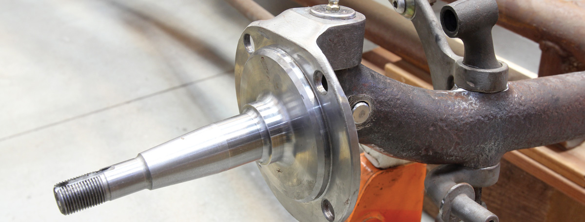
Recently, we sourced an original Henry Ford V8-60 front axle for our Project Potvin roadster. It was in decent shape, the kingpin and spring perch bores looked good. After careful consideration and thorough design of our chassis, it was decided that we would need to use a pair of Speedway Motors 3-3/4-inch dropped steering arms to clear the framerails of our one-off tube chassis. We had also decided to use their Bendix-style 12-inch drum brake kit, having installed a set on our Model A coupe and being thoroughly impressed. That said, it only made sense to use a set of their 1929-1948 spindles to mate the old and new. And since we were mixing up a couple new components with the old, we thought it was worth giving their Deluxe Spindle Kingpin Set a shot.

Speedway Motors’ Deluxe Spindle Kingpin Set does away with the old-style brass bushings, instead using a set of precision needle bearings pressed into the upper and lower spindle bosses. This design not only decreases the friction involved, providing easier steering and smoother operation but also negates the need for special tooling required to ream stock-style brass bushings to suit the kingpins. The stronger design is also easy to install and maintain, providing a cost-effective solution to the original, bushed design.
Altering the spindles to fit the brake kit backing plates
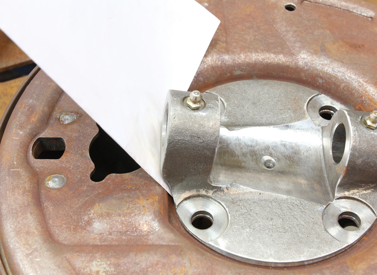
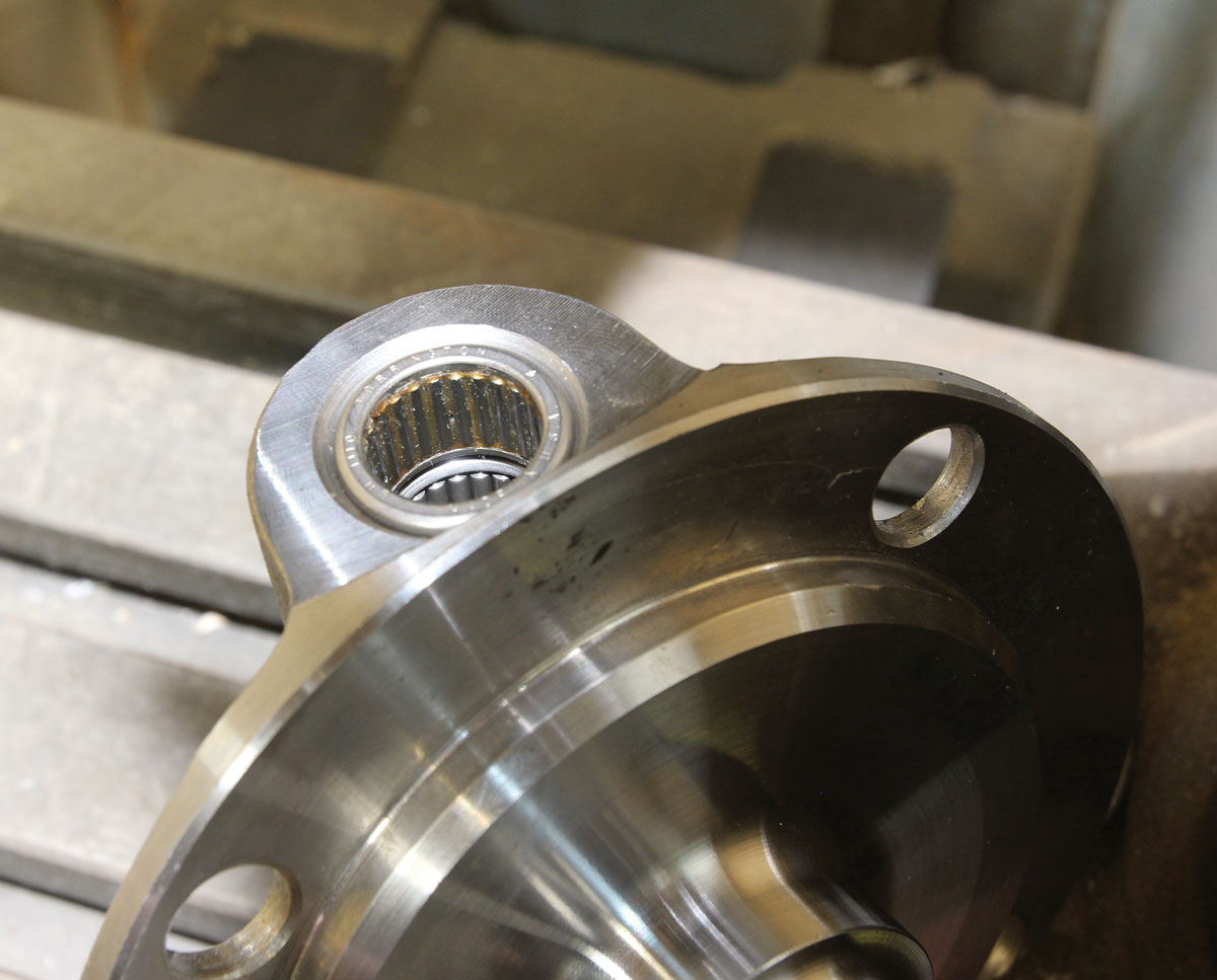
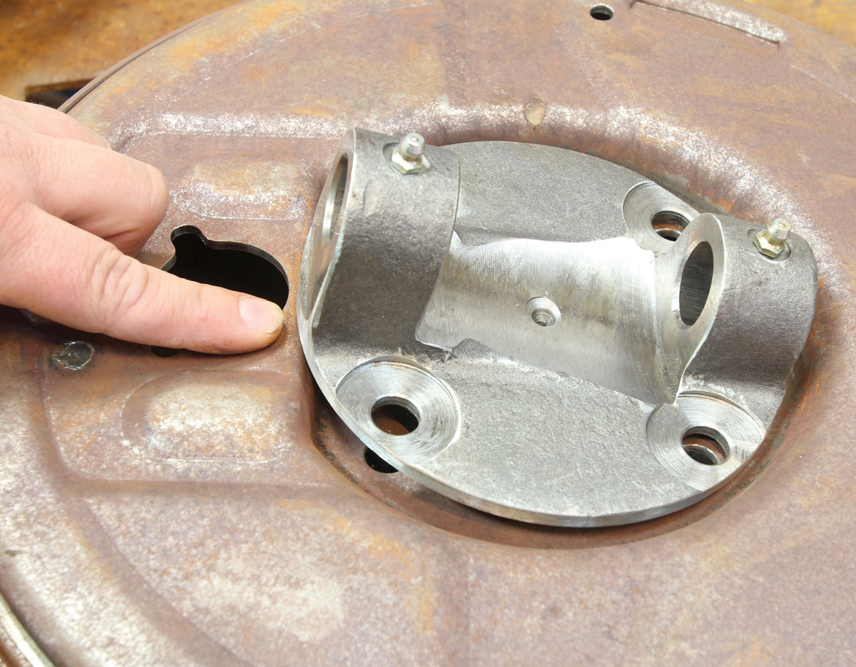
1. Before we begin the spindle installation for our roadster we need to modify the top of our Speedway Motors 1929-1948 Ford Forged Spindles (PN 91632104) to fit their 12-inch Bendix-Style brake kit backing plates (PN 91065420). Here you can see the area that needs to be relieved.
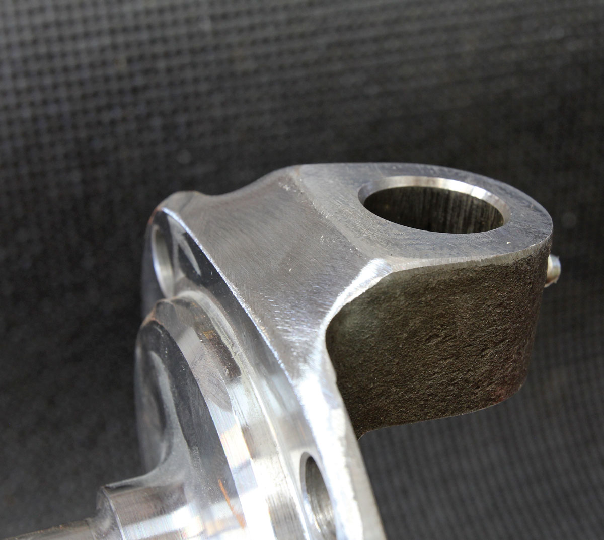
One end of the ground-down spindle
2. A 4-inch grinder with a 120-grit flap wheel made pretty quick work of clearancing our spindles, while still keeping things relatively smooth. A couple more minutes with a smaller sander will get things perfect before we paint.
piece of card stock working as a good indicator to check the clearance
3. A piece of card stock works as a good indicator to check the clearance as it gets close. Once the register of the spindle seats fully into the backing plate and the card stock can be slid between the two surfaces, you’re good to go.
stock-style kingpin bushing rebuild kit parts displayed on tablet
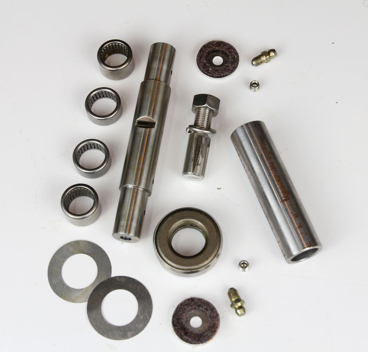
4. We’ve used the stock-style kingpin bushing rebuild kits in the past but thought we might try out Speedway’s fancy Deluxe Spindle Kingpin Set for 1937-1948 Fords (PN 91032115) for this project. We like the idea of using precision needle bearings instead of the original-style brass bushings and the fact that we won’t need to hone the bushings to get a nice, snug fit. The needle bearing design is also reported to provide superior strength, better lubrication, and easier steering than the stock-style setup. The kit consists of a kingpin, four needle bearings, shims, lock pin, grease fittings, felt gaskets, endcaps, setscrews to replace the spindle-mounted grease fittings, and a thrust bearing for each side. Also pictured is the bearing installation tool at right.
perch pin holes being cleaned
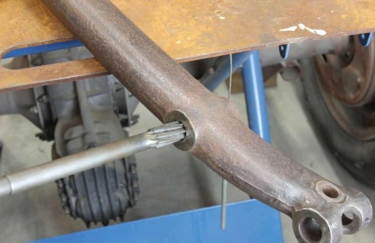
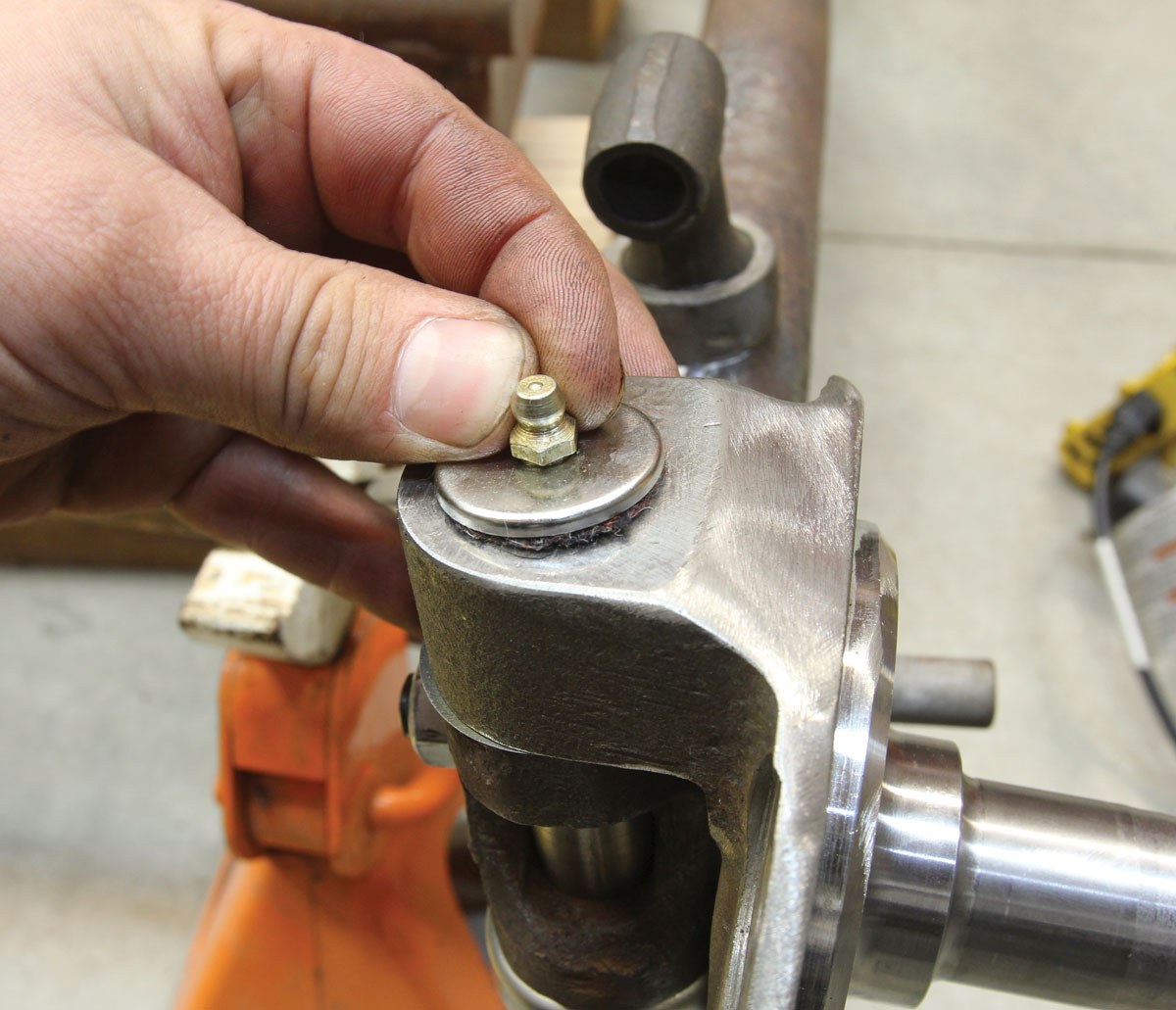
5. Before we begin the installation, I wanted to take a moment to clean out the perch pin holes in our V8-60 axle. Thankfully, the bores were pretty clear, so all we had to do was make a couple light passes with an appropriately sized reamer and we were good to go.
kingpin bores similar in shape
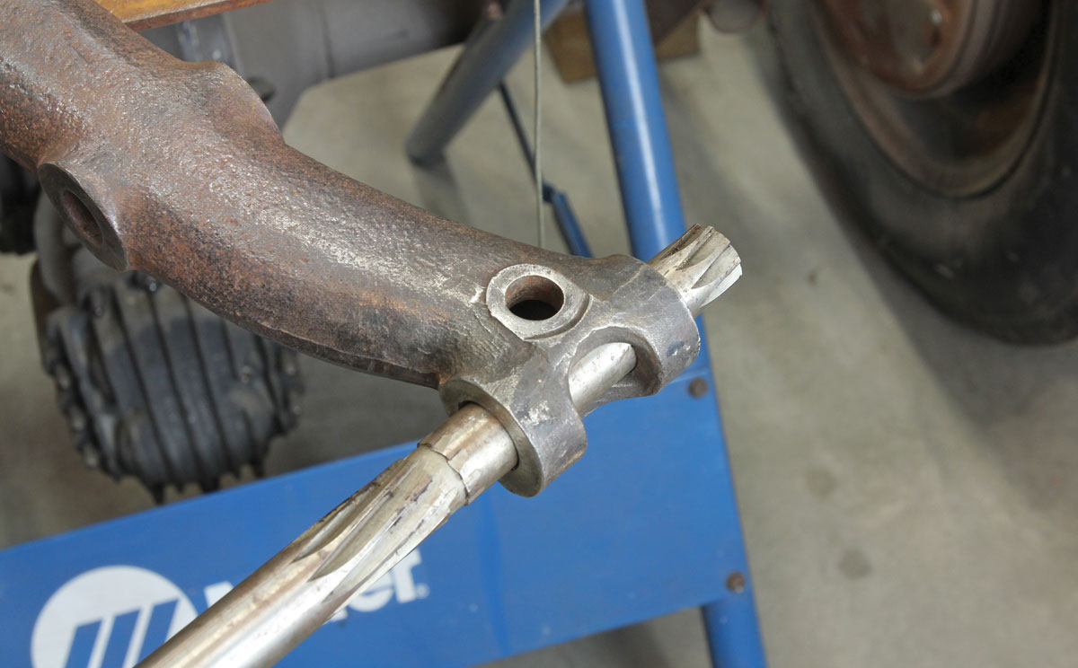
6. The kingpin bores were in similar shape and thus received similar attention. This old Snap-On King Bolt Reaming Tool has been in service since these old Fords were new, handed down from my great-grandfather, who was a Ford mechanic before the war. It’s little things like this that make working on these old cars so much fun!
parts properly prepped so the rebuild can start
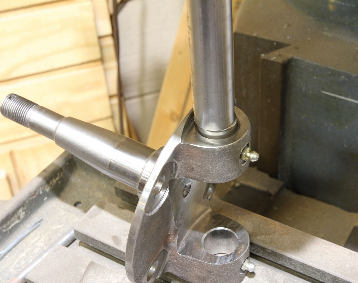
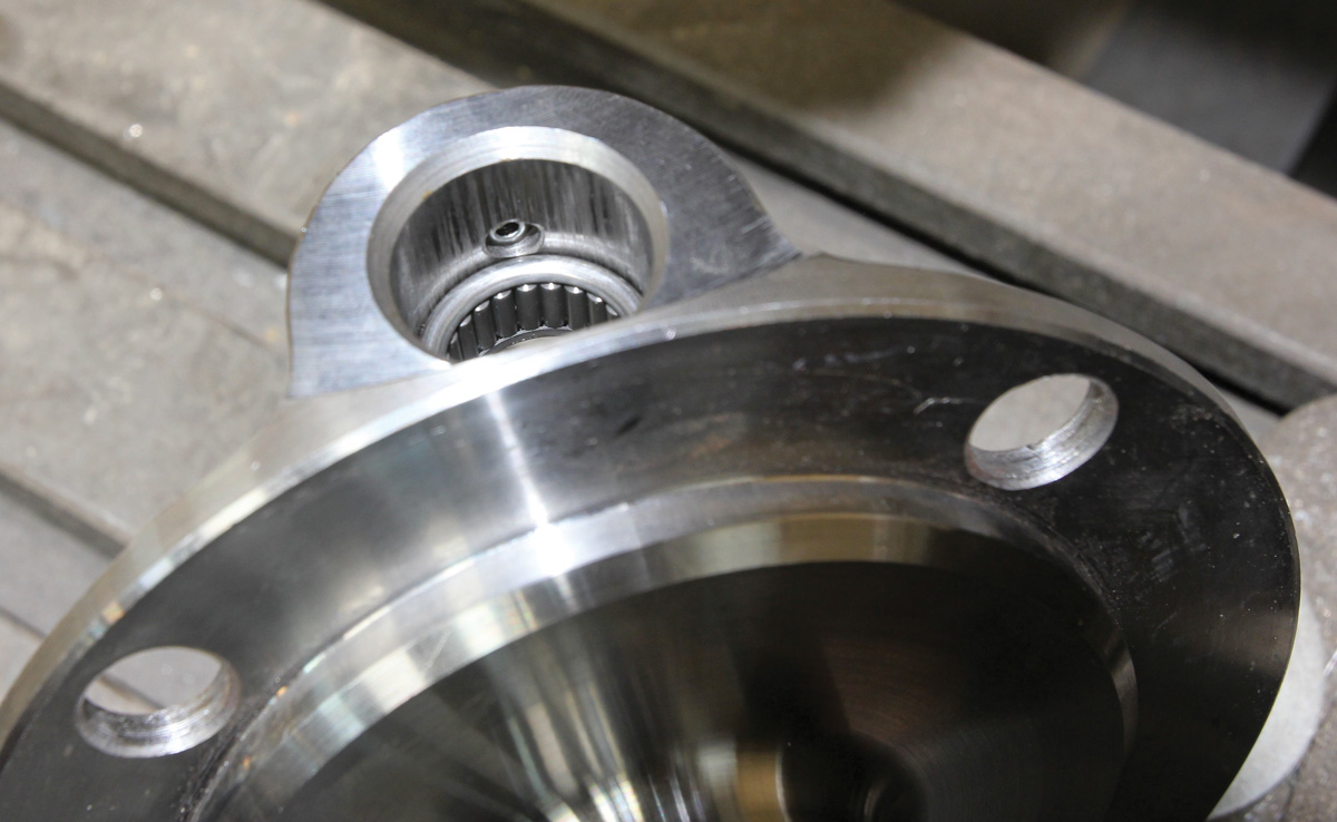
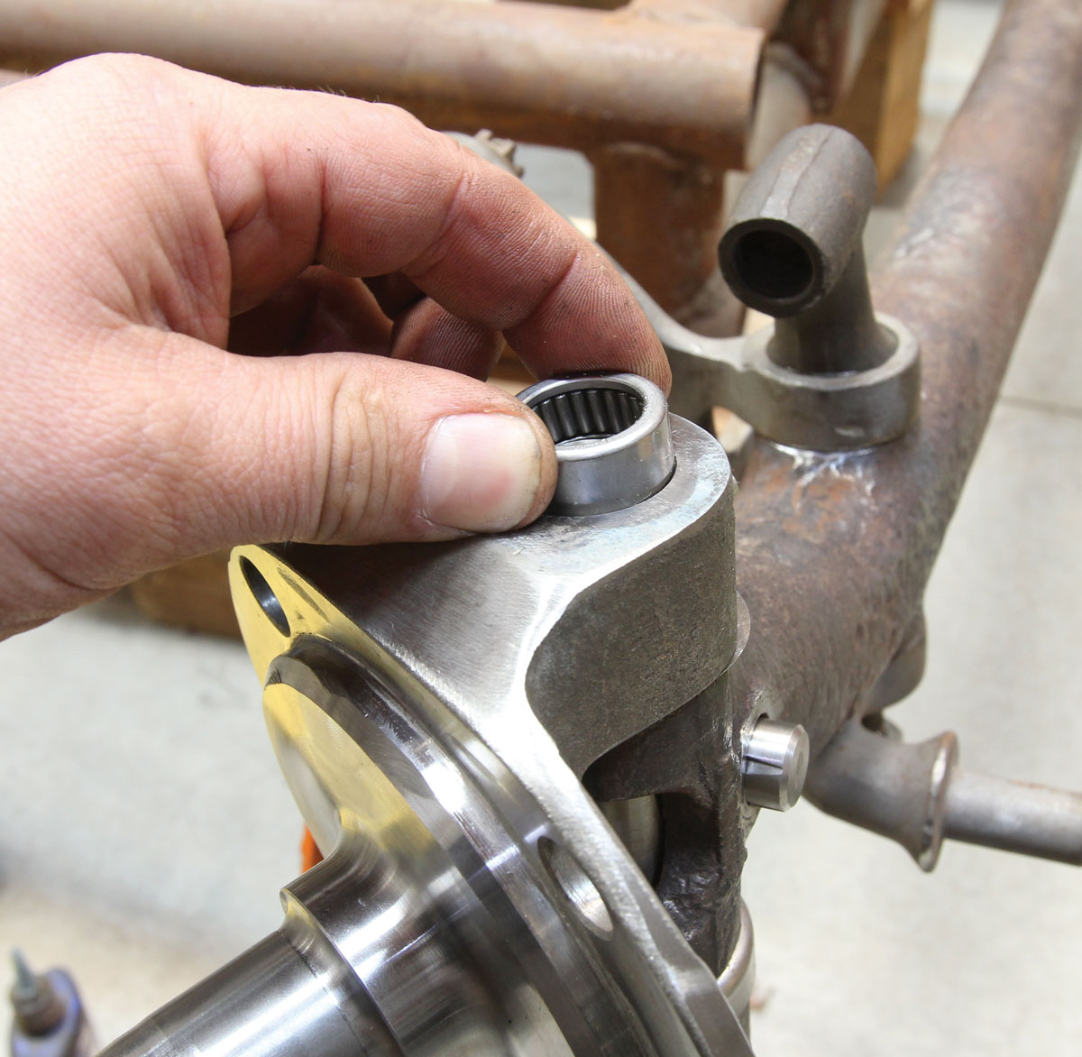
7. With all our parts properly prepped, we can now get started. The first step is to press the two lower needle bearings into the spindle. There are two different sized bearings; the taller bearings will be installed at the outside ends underneath the grease caps. Here, the bottom short bearing is being pressed into the spindle, flush with the top of the lower casting.
the bearings being installed
8. It’s important to only install the bearings until they’re flush with the spindle casting as this will provide a critical gap necessary to allow grease from the top or bottom fitting to reach the bearings through ports in the kingpin.
the bottom tall bearing being pressed into service
9. Next, the bottom tall bearing is pressed into service.
bearing flushed with the spindle casting and no further
10. Again, the bearing is installed until it’s flush with the spindle casting and no further.
two bottom bearings installed
11. The two bottom bearings are now installed.
the spindle being checked for any vertical play
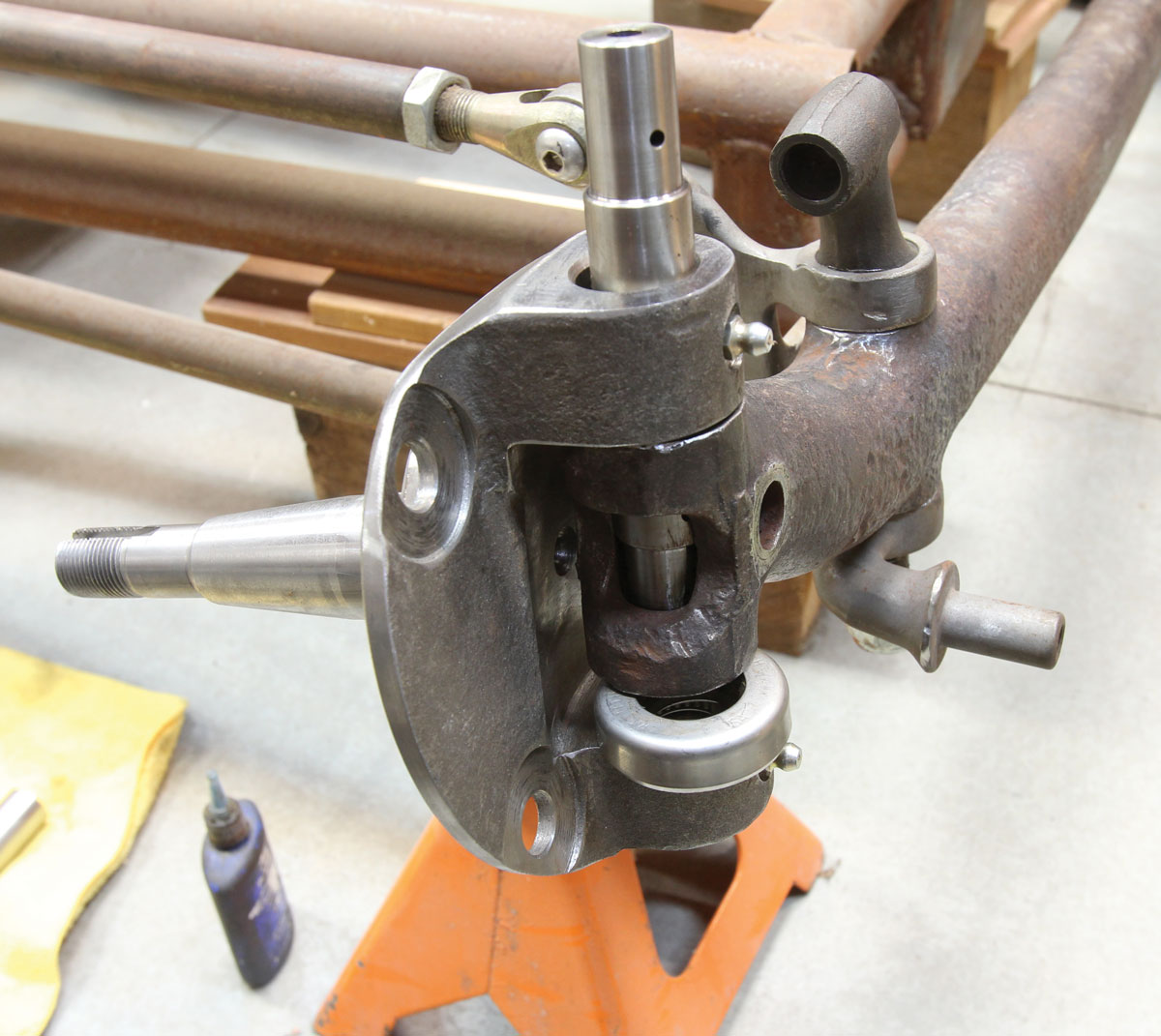
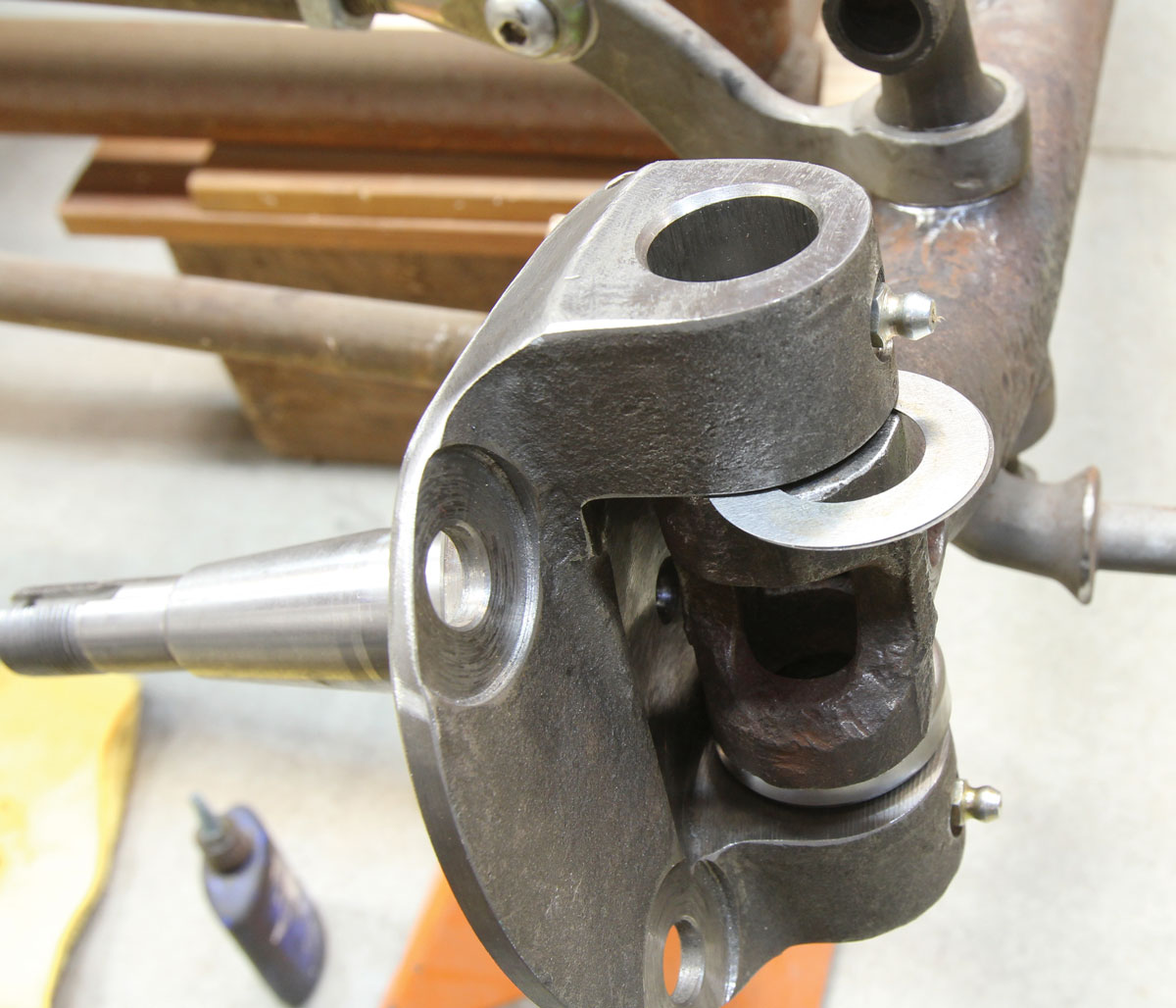
12. Next, we’re going to check the spindle for any vertical play. The spindle is slid over the axle, along with the thrust bearing before the kingpin is then slid down and through the lower spindle boss. Any excessive play at this point requires the installation of a shim or two, but no more than two, underneath the upper spindle boss. Any play above that indicates excessive play and indicates a worn axle. Worth mentioning here is the installation of the thrust bearing, with the seam facing down, to prevent water intrusion into the bearing.
axle requiring two shims on the passenger side
13. Our axle did require two shims on the passenger side, but none on the driver side. Thankfully, this axle should be good to go.
kingpin reinstalled
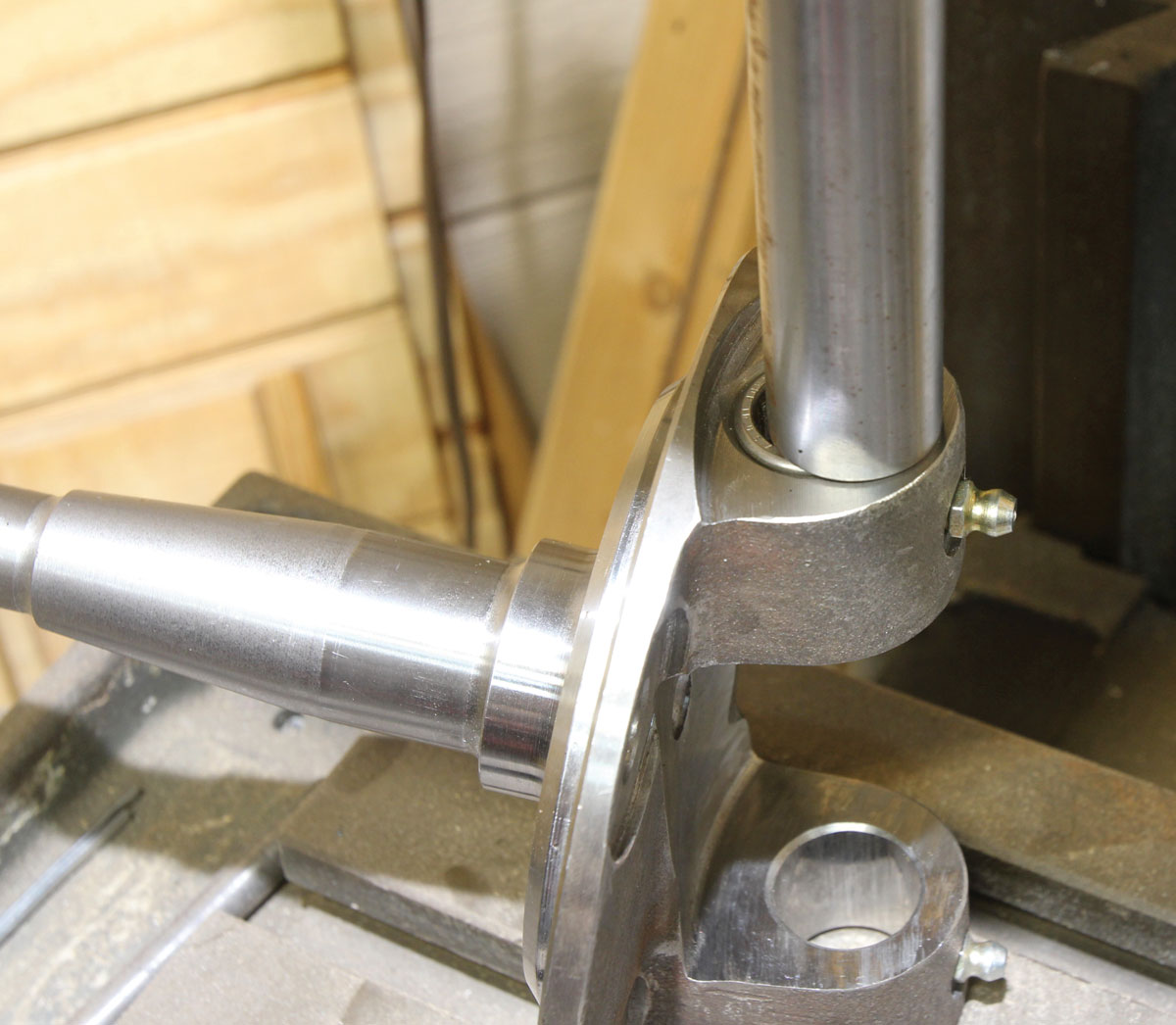
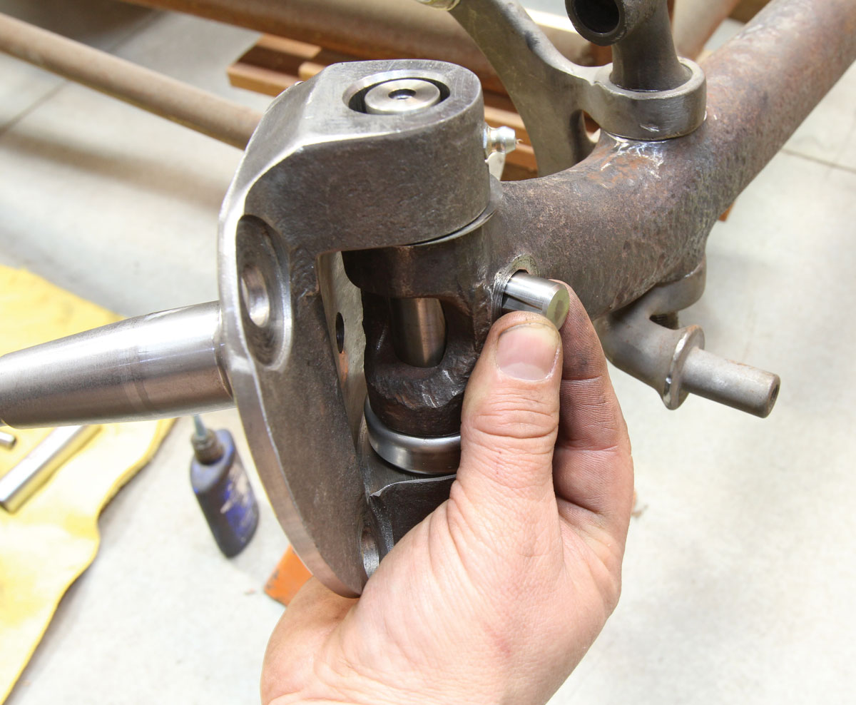
14. With the spindle shimmed, the kingpin is reinstalled with care so as to not damage the delicate shim(s) and, with the notch lined up with the lock pin hole in the axle, the lock pin can then be installed. For now, the lock pin nut and washer are only installed finger tight.
the upper short bearing installed
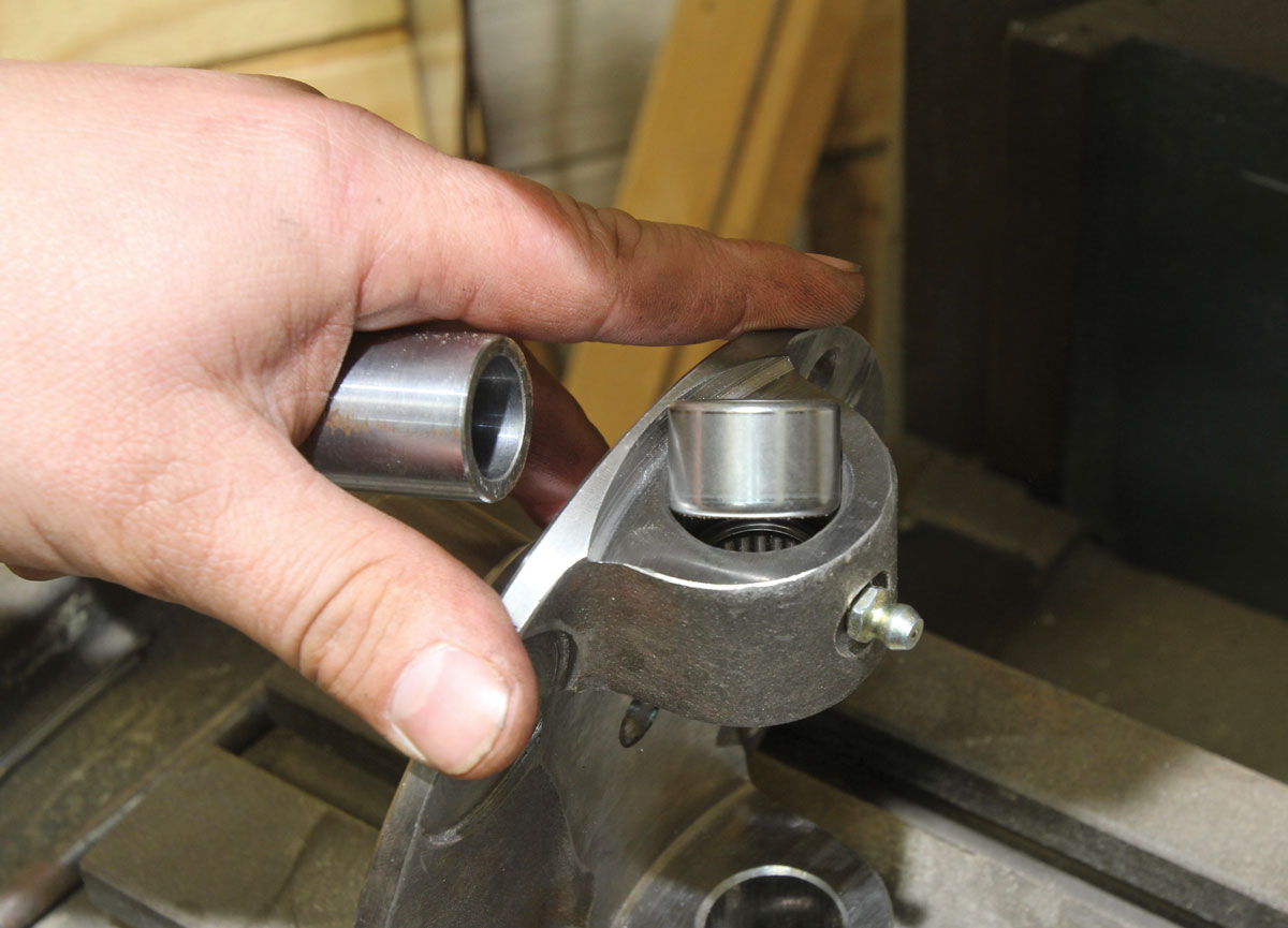
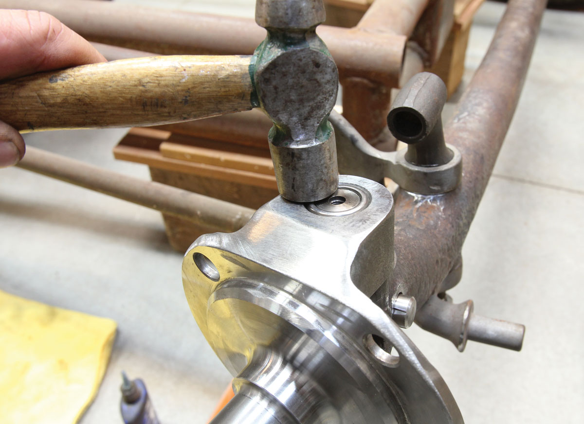
15. Next, the upper short bearing is installed into the spindle boss using the provided installation tool. This bearing will be driven in until it bottoms out against the axle.
upper tall bearing driven with flush with top surface of the spindle
16. The upper tall bearing is installed last, driven just flush with the top surface of the spindle. This will again leave a small gap between the two bearings to provide a path for lubrication. With the kingpin installed and all four bearings pressed in place, now is a good time check for any excessive play and that the spindle moves freely throughout its travel.
Speedway Deluxe Spindle Kingpin Set designed to lubricate the inner bearings
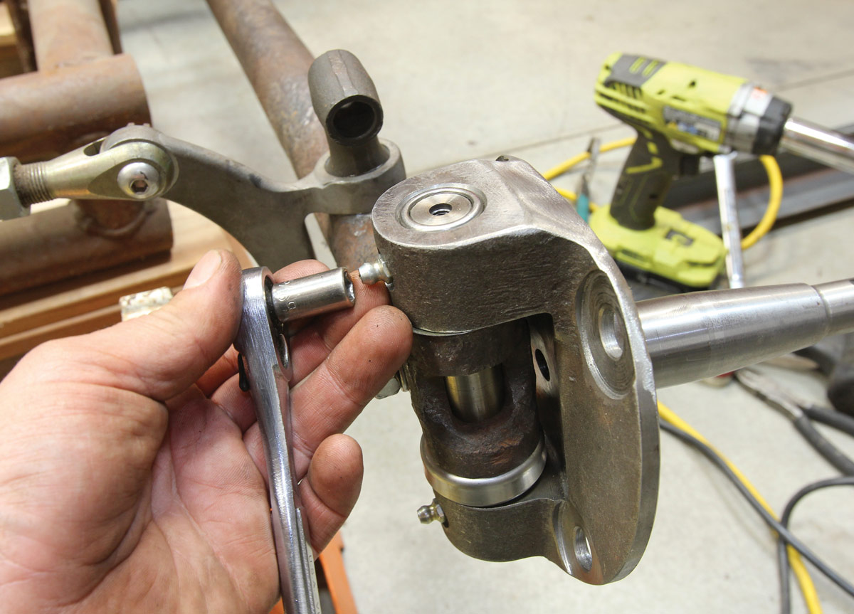
17. The Speedway Deluxe Spindle Kingpin Set is designed to lubricate the inner bearings via top- and bottom-mounted grease fittings, negating the need for the spindle-mounted fittings. So, we’ll be replacing these fittings …
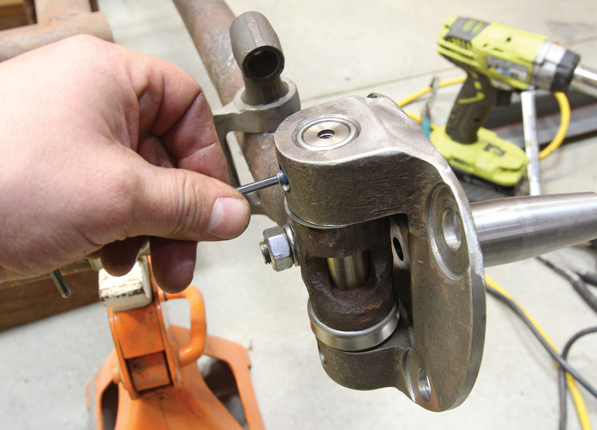
stainless steel setscrews provided in the kit
18. … with the stainless steel setscrews provided in the kit. A small drop of thread locker is used as the setscrews only need to be installed until they’re flush with the surface of the spindle. Any further and they could push against the spindle bearings.
felt gasket, covered by a stainless steel endcap
19. A felt gasket, covered by a stainless steel endcap is held in place by a new grease fitting at the top and bottom of each kingpin.
lock pins being tightened
20. With the installation complete, all that’s left is to tighten the lock pins to 55-60 ft-lb, grease the fittings, and hit the road!
 SOURCES
Speedway Motors
(800) 979-0122
speedwaymotors.com
Clampdown Competition
clampdowncomp.com
Modern Rodding
VOLUME 2 • ISSUE 8 • 2021