 By Gerry Burger
e’ve been following along with Troy Gudgel and the team at BBT Fabrications as they transform Bill Sather’s 1934 five-window coupe from a rough old hot rod into a state-of-the-art exercise in modern rodding. After re-chopping the coupe (see Modern Rodding Mar. ’21 issue) Gudgel turned his attention to building a better firewall.
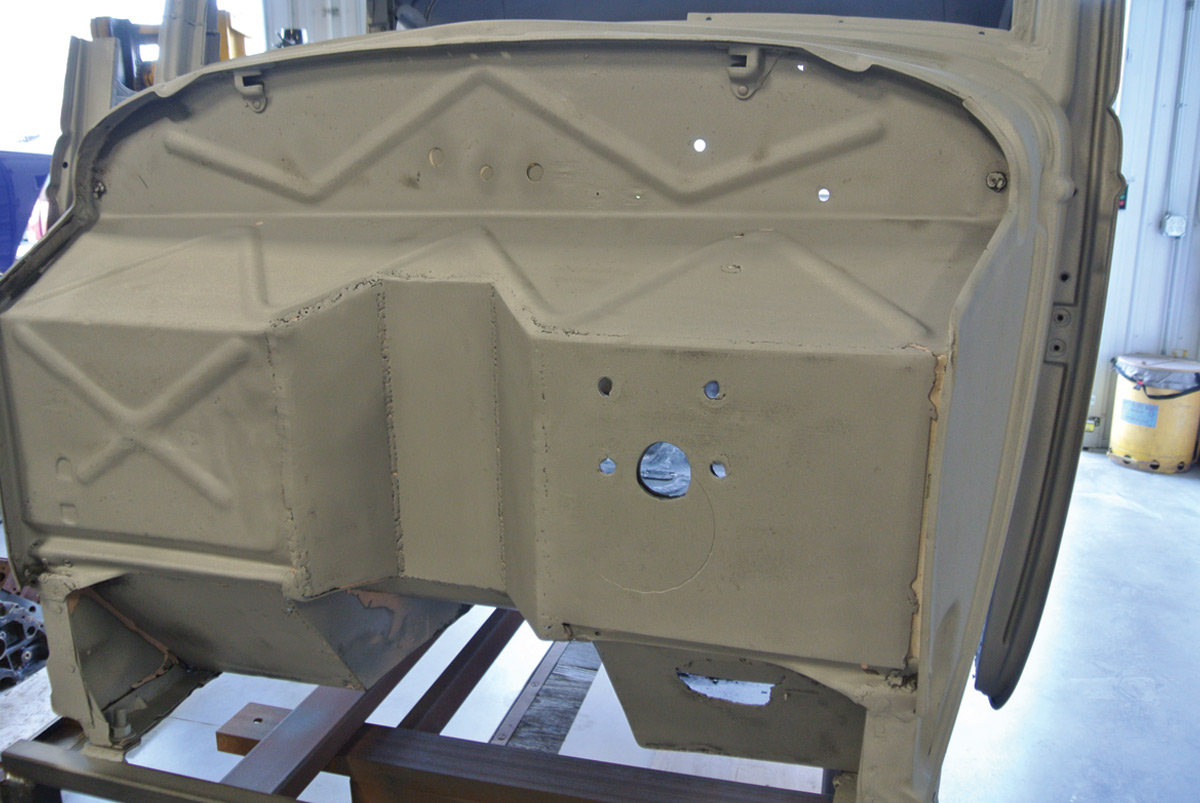
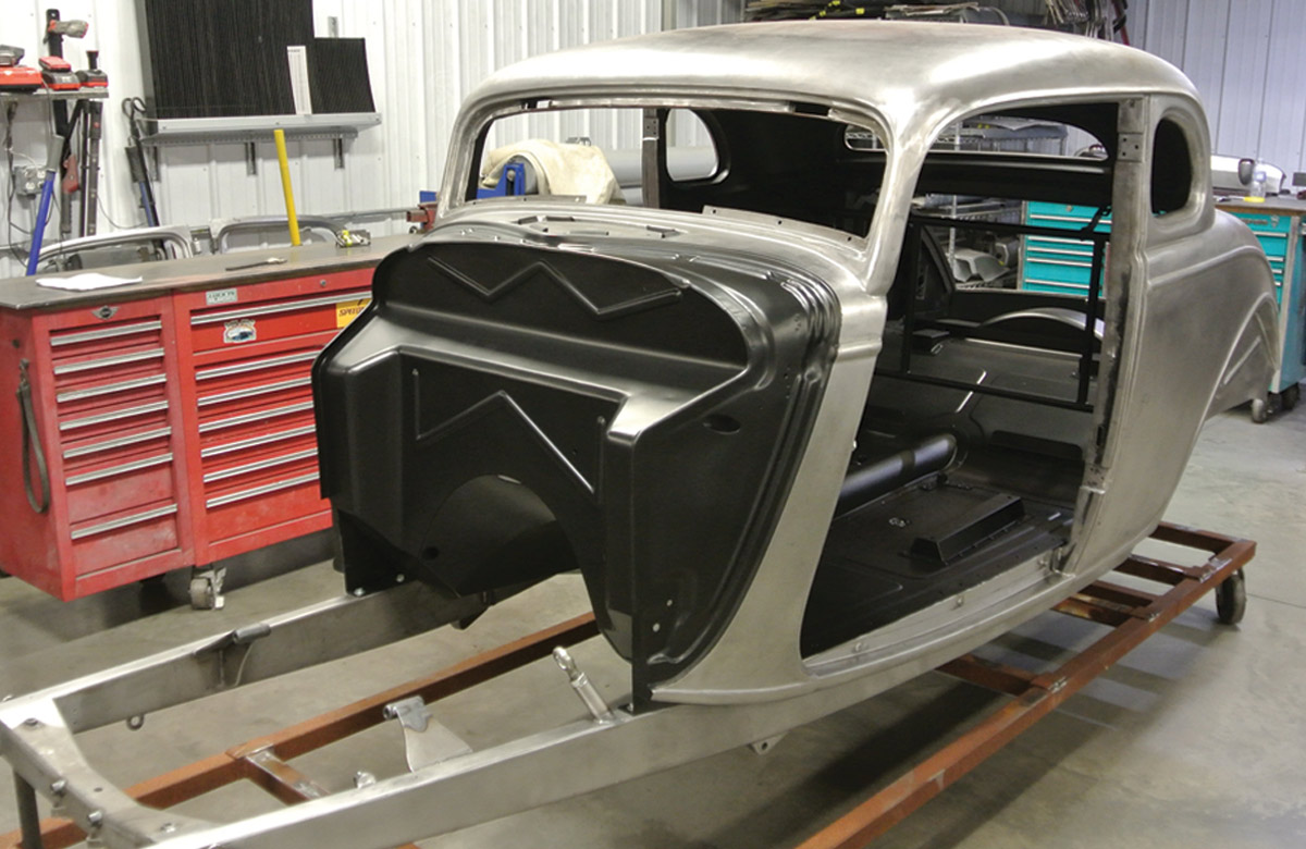
After blasting the original firewall clean, it uncovered the original 1934 Ford five-window coupe firewall modified in typical hot rod fashion of years past. Actually, as original hot rod firewalls go, this one was in above-average condition. The typical notch had been welded in for distributor clearance. The four mounting holes told us at one time the car had a power brake master cylinder mounted to the driver side firewall over a reinforcing plate that had been welded in place when the distributor notch was formed. Once again we’ve seen worse modifications and many more holes, but this coupe was being completely transformed so this firewall had to go.
Three major differences would dictate the shape of the new firewall. First, the new chassis would incorporate an under-the-floor Wilwood master cylinder. This location facilitates 1934 Ford factory-style, through-the-floor pedals, eliminating the firewall-mounted swing pedals once fitted to this old hot rod.
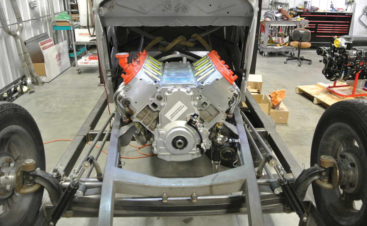
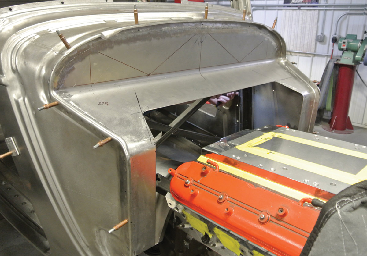
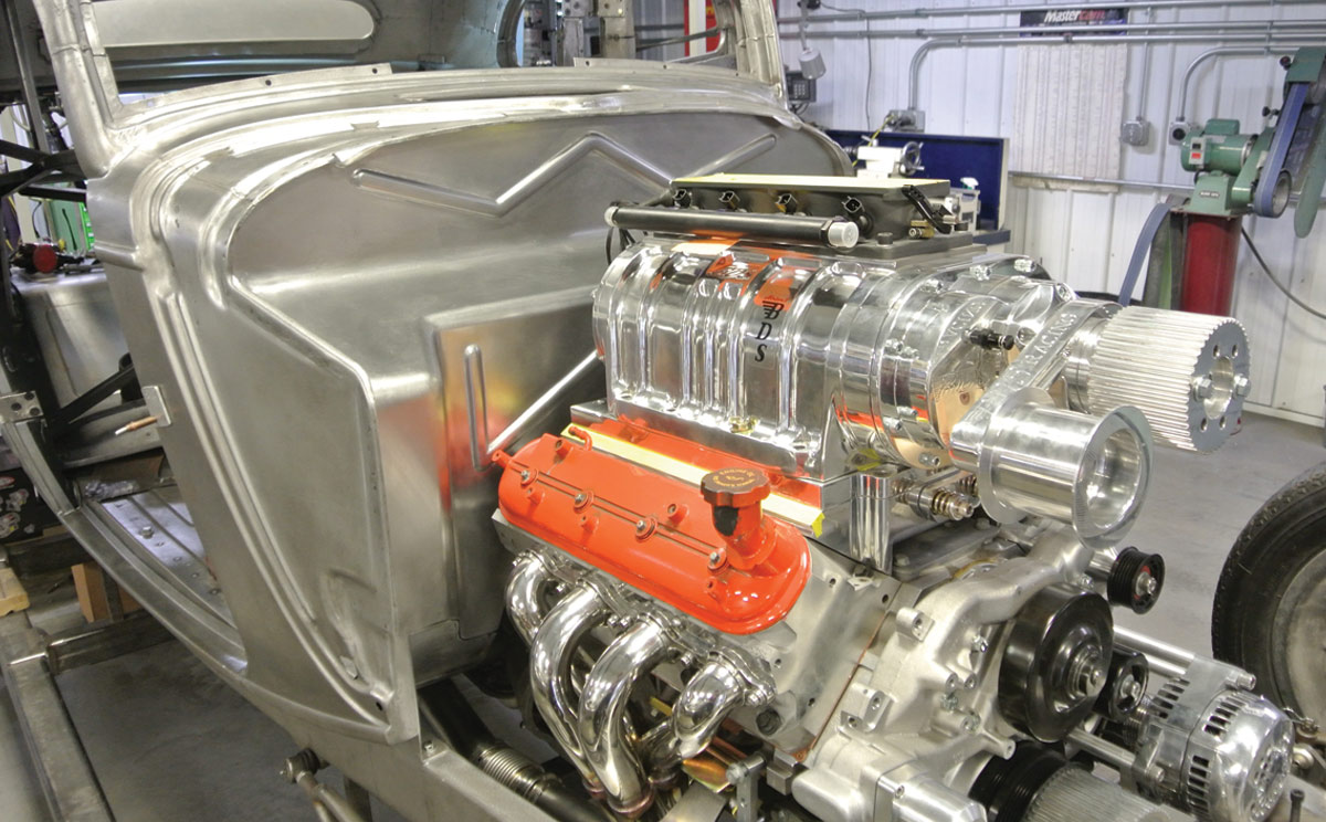
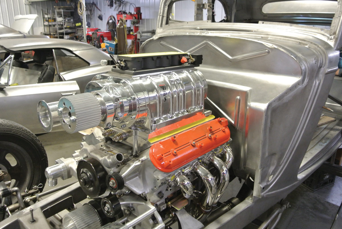
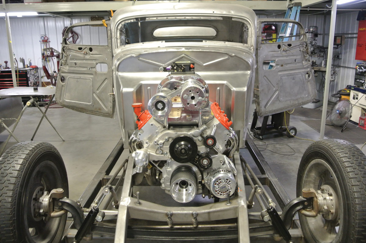
The second major change to affect the shape of the firewall was the new 427 LS blower motor from Texas Speed now nestled between the framerails. This required a deeper recess to allow access to the distributor and the rear of the blower.
Finally, the third major change was forming a transmission tunnel to provide clearance for the 4L75E transmission. This change would drastically change the lower center portion of the firewall and also dictate the shape of the floor. Armed with these three requirements, Gudgel pulled out the sheetmetal and put on the thinking cap.
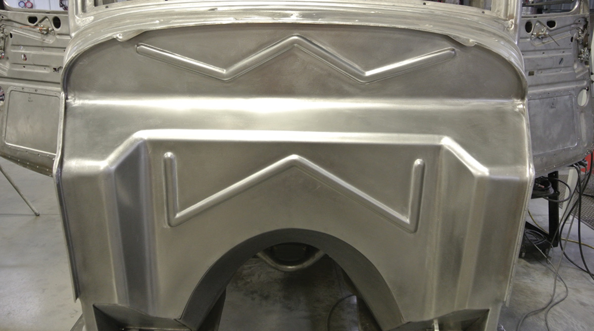
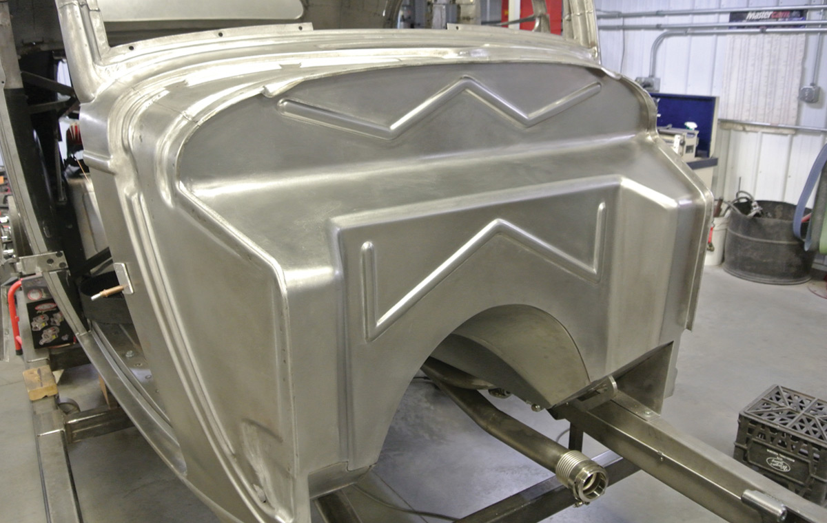
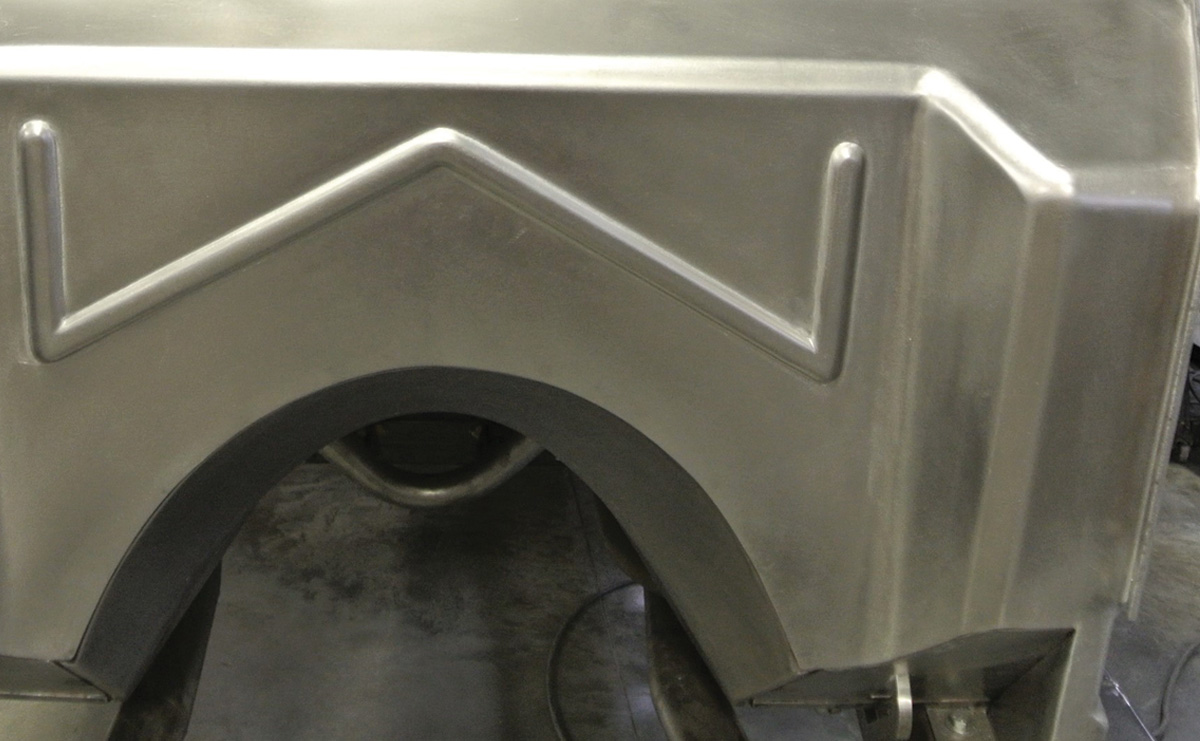
Great hot rods incorporate equal portions of two things … form and function. Combining those two things will generally provide a good hot rod piece. When it came to form, Gudgel wanted to maintain the general shape of the original firewall, including the shape of the stamped beads in the firewall. The new stampings on the upper firewall are not exact replicas, rather they are inspired by the originals. The lower portion of the firewall is completely different, so the stamped beads were designed to complement the upper stampings. This would provide a strong firewall with a design reminiscent of the original firewall while incorporating clearances for one very modern driveline.
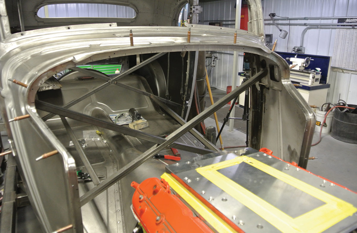
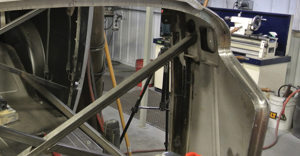
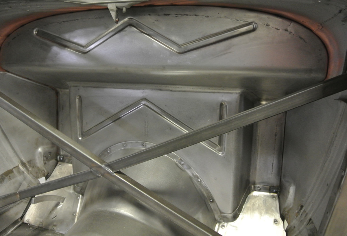
Having a vision and having the ability to convert that vision into reality can be challenging for the home builder, but this is simply what BBT Fabrications does on a daily basis. The first step was to remove the lower portion of the original firewall and install the engine and transmission to check for required clearances. Next the inside of the body was crossbraced to ensure body alignment is not compromised while fitting the new firewall. After the crossbracing was in place, the top half of the firewall was removed and the inner structure was ground clean.
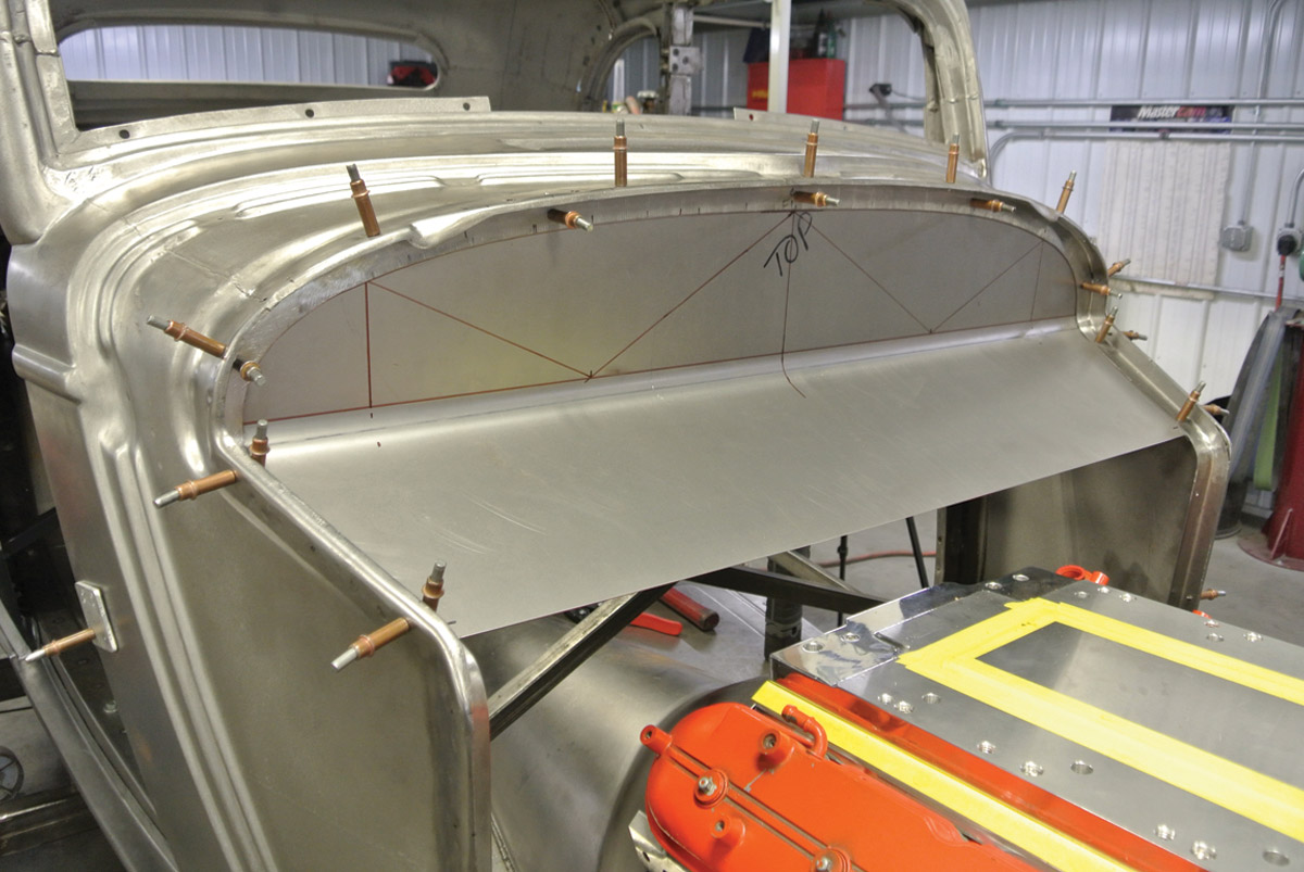
Fabrication of the new firewall begins with a 90-degree flange formed around the entire perimeter of the firewall opening. This sounds simple, but is not easy. It involves multiple compound curves to make a perfect fit. Making curves in a 90-degree piece of sheetmetal involves stretching the flat portion and shrinking the vertical portion. Using a Pullmax machine makes this a much simpler task. It still takes skill and patience to form the flange. The flange will be formed in multiple pieces and then welded together and metal finished before being fitted inside the cowl. This flange is the mount for the new firewall. Cleco panel fasteners through the cowl hold the fabricated flange in place while the firewall panels will be fitted to this flange. Next a posterboard template was made for the shape of the top half of the firewall. This template was traced to a piece of 18-gauge steel and it was cut to shape. The proper angle was bent into the sheetmetal and the piece of sheetmetal was fit to the flange around the firewall opening. Next, two pieces of sheetmetal were rolled to form the vertical pieces on each side of the firewall. This new firewall panel is trimmed to precisely fit the flange and then the two pieces are tack-welded together. After they are tack-welded in place, the final welding and metal finishing is completed. You now have a new firewall with a flange that fits the cowl perfectly.
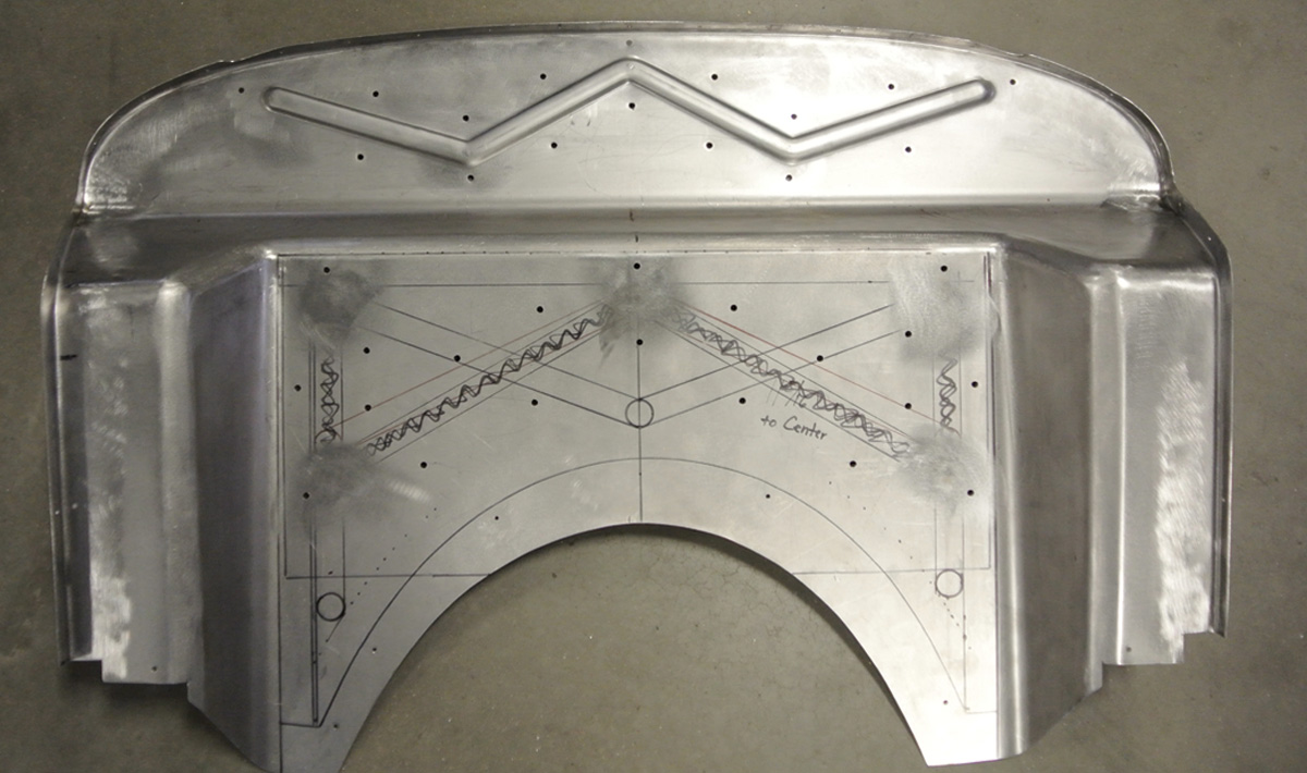
The final piece to the firewall puzzle was the center piece that resides directly behind the motor. This piece was formed to fill the opening, go over the transmission, and also connect to the two vertical pieces of the upper firewall. It should be noted there are no square edges on the entire firewall and all bends are done on a radius for a smooth-flowing look. Adding to that “no square edge look” is the addition of an angle where the lower firewall panel meets the upper firewall panels. This angle really completes the smooth-formed look of the completed firewall.
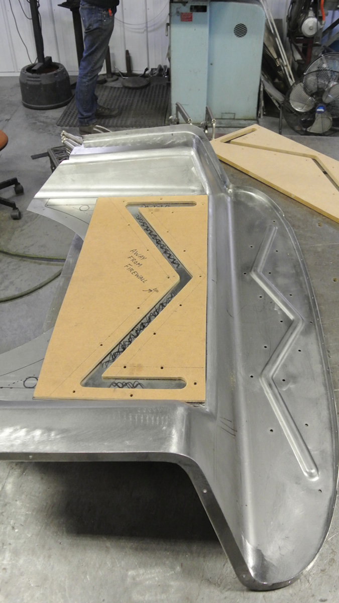
With the sheetmetal work, welding, and metal finishing complete it was time to stamp the beads into the finished firewall. While a bead roller can sometimes be used to roll beads on a panel, in this case Gudgel opted to stamp the beads into the panel using a Pullmax machine. Custom stampings involve building a set of forms from 3/4-inch particle board. The design is carefully laid out on the particle board and the shape of the bead is formed with a router. These two panels must firmly fit over the sheetmetal, so the lower particle board panels were held together with 22-1/4-inch bolts, while the upper panel dies were sandwiched with 16 bolts. The bolt heads must be countersunk to provide a smooth surface to feed through the Pullmax machine. You will need a particle board form on both sides of the panel, so clamp the two pieces of particle board together and cut the bead shape through both panels to ensure perfect alignment. With the design and shape of the bead cut into both pieces of particle board your stamping forms are complete. Think of it as a sandwich form, with the firewall panel in the middle. With the forms precisely located on the sheetmetal panels and bolted in place, it is time to begin forming the beads. Gudgel carefully fed the panel through the Pullmax as it hammered out the beads.
You now have a finished firewall that fits the body opening perfectly. Install the finished panel and hold it in place with Cleco fasteners. Tack weld the firewall to the body and then finish welding the firewall to the body, alternating welding sites to prevent warpage. Metal finish the welds, and just like that you have one very cool firewall with equal parts engine clearance, strength, and good looks.
 SOURCES
Wilwood Disc Brakes
(805) 388-1188
wilwood.com