Modern Rodding Tech icon
Stop It!
Speedway Motors’ kit is ideally suited for combining the large brake shoe Lincoln front brakes and early Ford spindles onto a solid axle.
By Eric Geisert | Photography By the Author
Viewing LINCOLN FRONT BRAKES AND EARLY FORD SPINDLES ONTO A SOLID AXLE
M

aking stuff work together when it wasn’t originally designed to be is the cornerstone of hot rodding, but doing that is often more than half the challenge. Step in Speedway Motors and their Lincoln front brake kit for early Ford spindles.

For many years, if someone wanted to use 12×2-inch Lincoln drum front brakes (mostly because the brake shoe is 1/4-inch wider) they had to cobble something together, and if you were using 1937 – 1941 Ford spindles (the ones with the round, not square, back) then you had to bust out the heavy grinder and attack the top of the spindle so the Lincoln backing plate would fit flush. Up until just recently, that was how it was done.

Speedway Motors has recently expanded their line of hot rod brake systems and parts to be more friendly to the needs of a traditional hot rodder who wants the vintage look without having to resort to using possibly stressed-out 80-year-old parts. Speedway saw the need for a simpler approach and began manufacturing forged spindles that have that clearance already precision milled into the piece, saving hours of work grinding to achieve the desired result. And they offer several “kits” that group all the needed parts together, making ordering a snap. The only non-Speedway parts used for this build was a pair of Super Bell steering arms from Pete and Jakes.

We found some folks will want to assemble these brake components on the mounted spindle, while others (like us) will do the work on a workbench and then transfer the assembled parts to the spindle. Either way you can now build a vintage hot rod Lincoln drum—based brake system using only brand-new parts, and this is how it’s done.

SourceS

Speedway Motors
(800) 979-0122
www.SpeedwayMotors.com

Pete and Jakes / Super Bell
(800) 334-7240
www.PeteAndJakes.com
A look at the The Speedway Lincoln drum kit
01 The Speedway Lincoln drum kit comes with all the necessary brake components, including the iconic finned drums, backing plates, shoes, springs, adjusters, wheel cylinder, clips, and more.
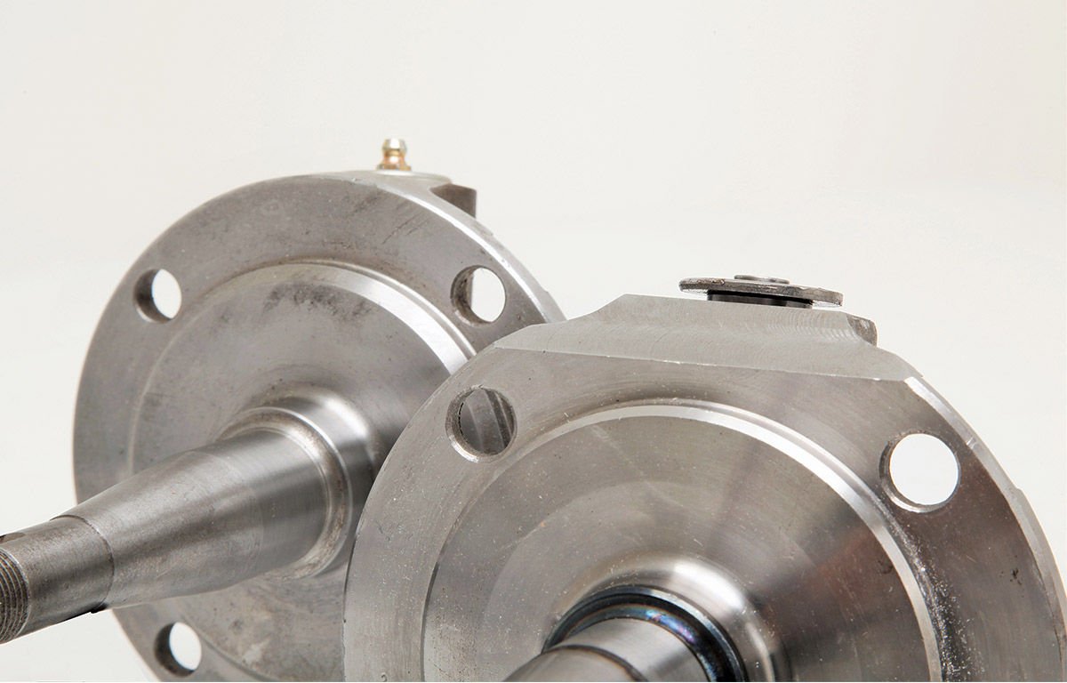
A stock-type aftermarket spindle and the Speedway drop-forged milled spindle (PN 91032111)
02 A stock-type aftermarket spindle is in the background and the new Speedway drop-forged milled spindle (PN 91032111) is in the foreground, with the milled/clearanced area between the mounting holes at the top of the spindle clearly visible.
Looking at how the the stock-type spindle does not fit flush to the backing plate
Seeing how the new Speedway spindle fits perfect
03 You can see how much material would have to be ground in the top photo as the stock-type spindle does not fit flush to the backing plate. The new Speedway spindle (above) fits perfect.
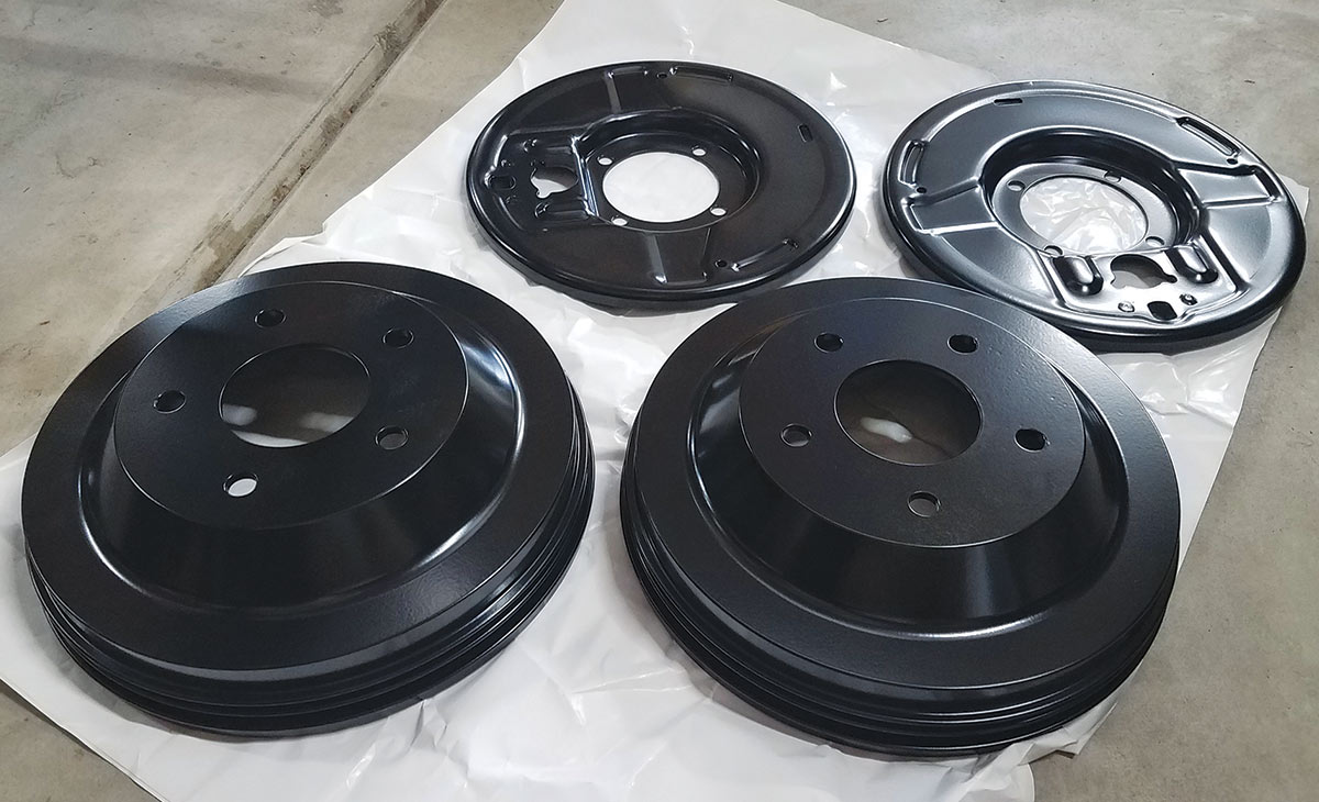
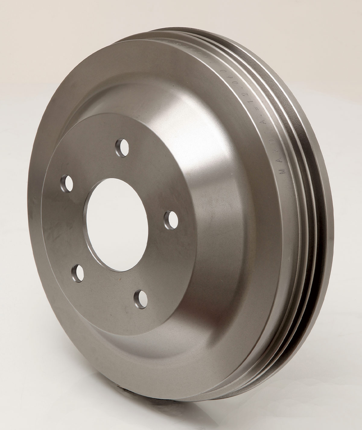
Powder coated Speedway Motors’ Lincoln-type 12×2-inch Bendix-style brake drums
04 We powdercoated both the Speedway Motors’ Lincoln-type 12×2-inch Bendix-style brake drums (PN 91065400) as well as the backing plate in a satin black finish, and then painted the spindles to match.
Using an arbor press the bushings are pressed into the painted spindle
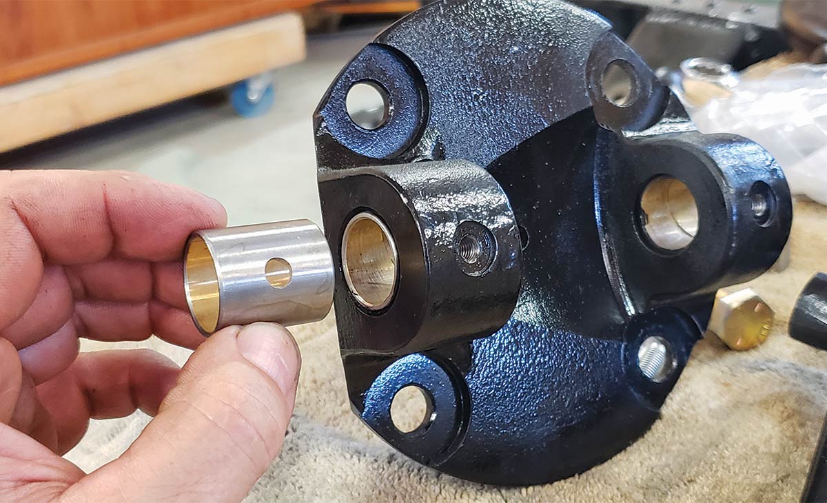
05 Using an arbor press the bushings are pressed into the painted spindle so the hole lines up with the hole for the threaded Zerk grease fitting, which gets added next.
Looking at the The Speedway 1937-1941 kingpin set
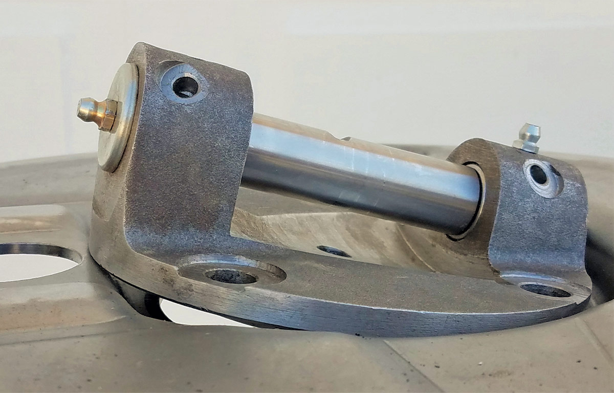
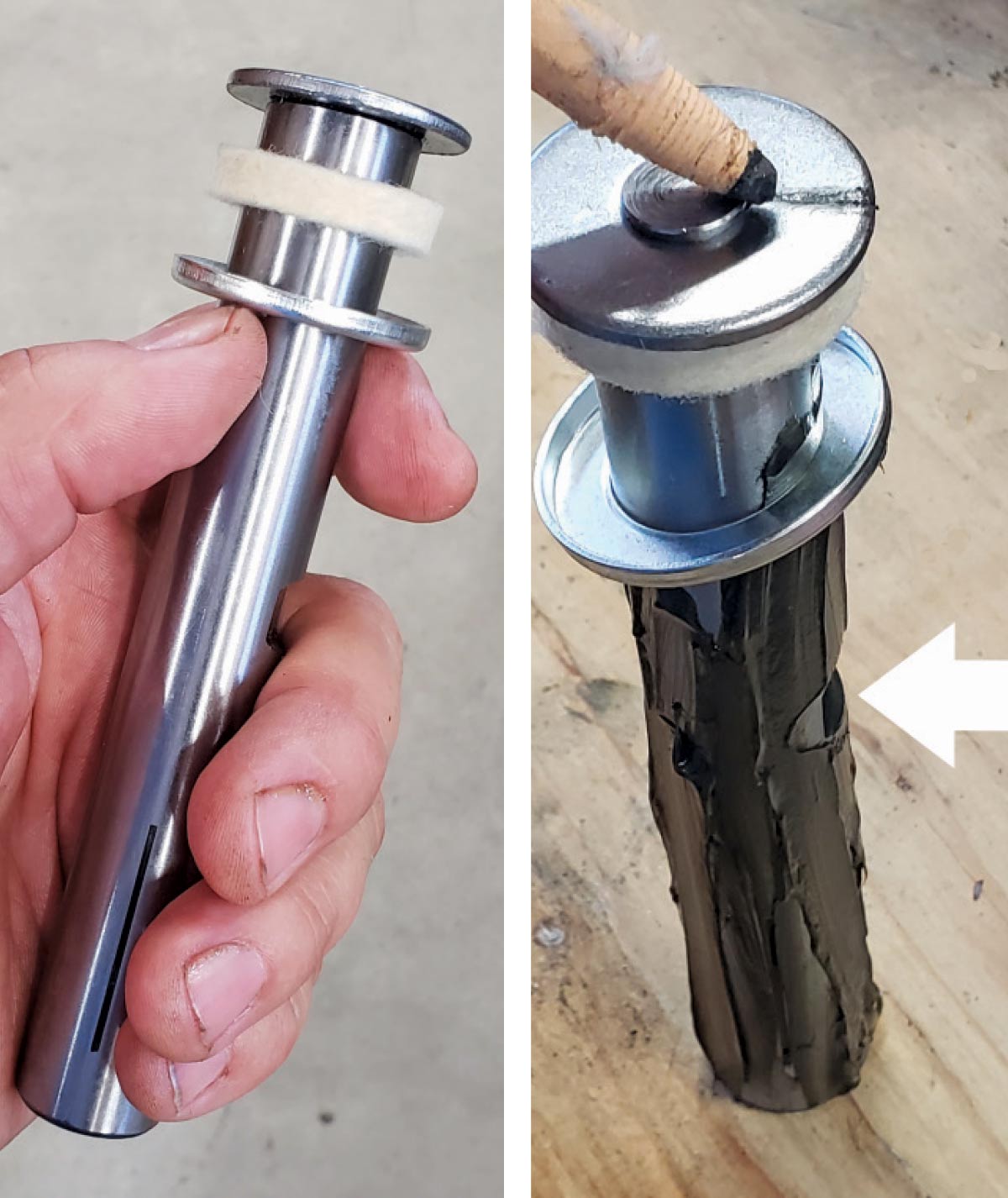
06 The Speedway 1937-1941 kingpin set (PN 91032121) comes with the necessary bushings, bearings, and lock pins. To make sure the notch (see arrow) will line up with the lock pin hole, mark the notch’s location on top of the kingpin with a marker, then add grease to the pin to make the installation easier.
The inner and outer wheel hub bearings
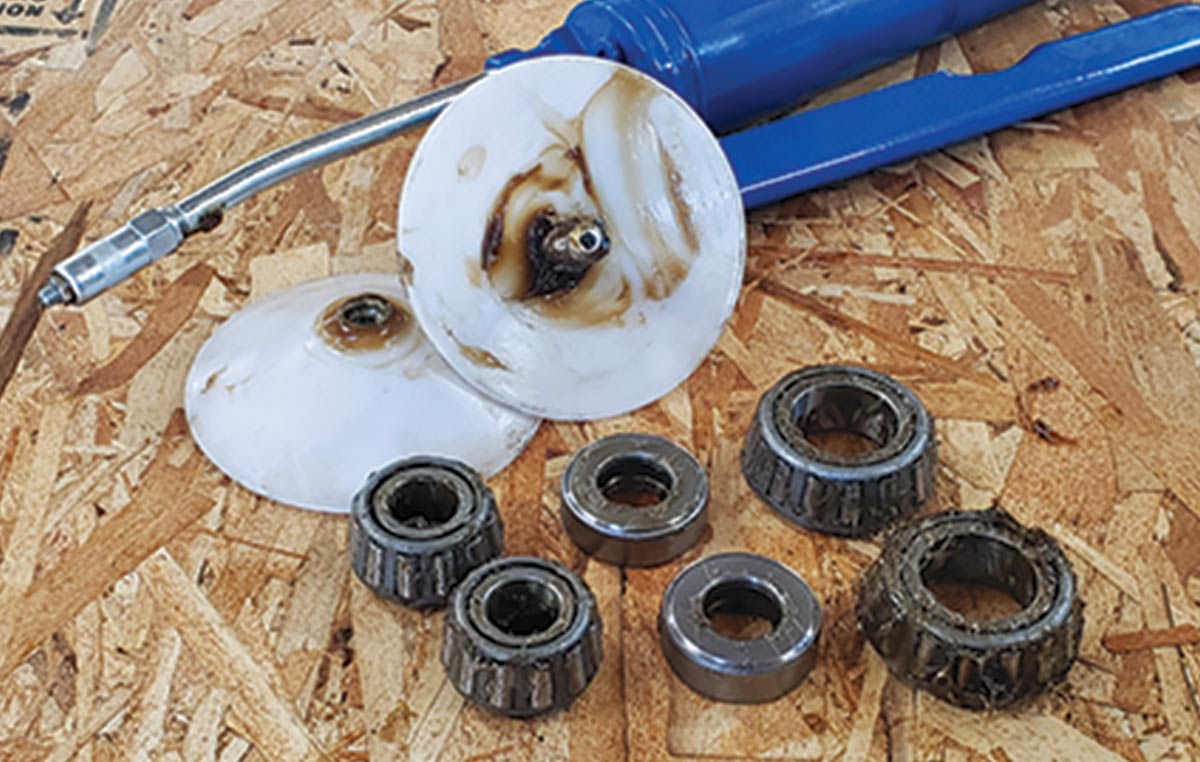
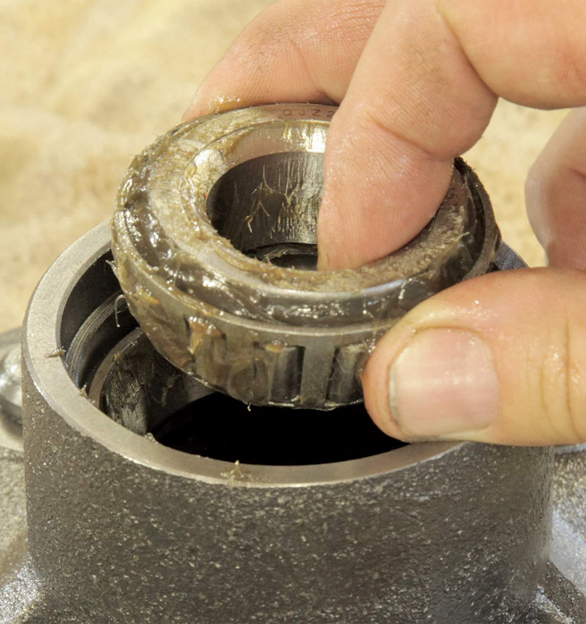
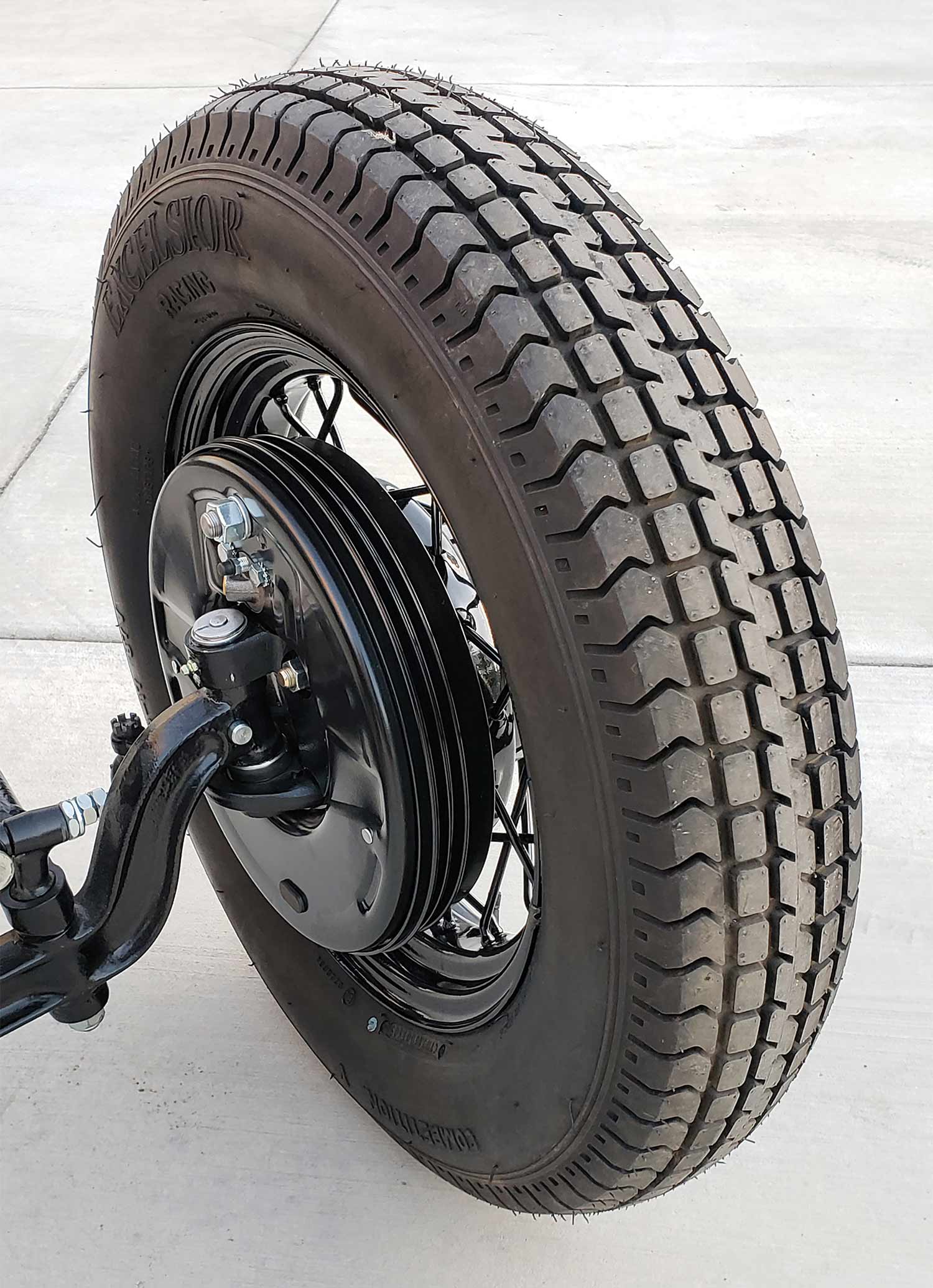
07 The inner (larger, on right) and outer wheel hub bearings (along with the kingpin bearings) all get heavily packed with grease.
Placing the kingpin bearing on top of the lower spindle “ear”
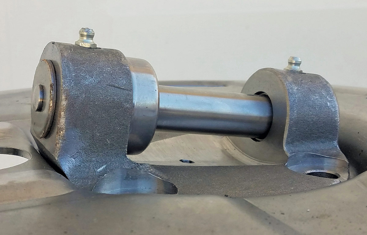
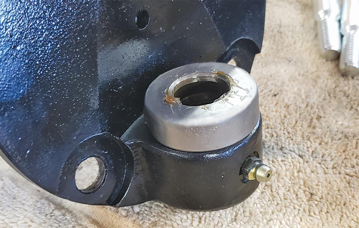
08 Place the kingpin bearing on top of the lower spindle “ear” (the kingpin will eventually hold it in place) with the rounded, smooth side of the cup facing up and its seam on the bottom. Partially install the kingpin and check the gap between the upper spindle “ear” and the axle boss. If there’s a gap of more than 0.015-inch then use the supplied shims to take up the slack as you want a gap of between 0.005 and 0.015-inch. (You probably won’t need them by using all brand-new parts.)
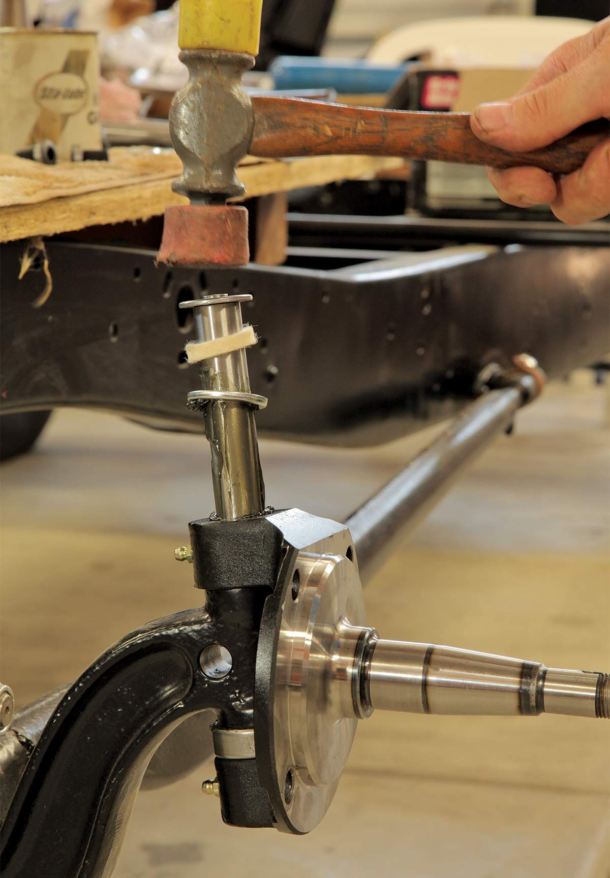
The greased kingpin is tapped into place
09 Next the greased kingpin is tapped into place, keeping an eye out to align its notch with the hole in the axle for the threaded lock pin.
Installing the pin from the front of the axle
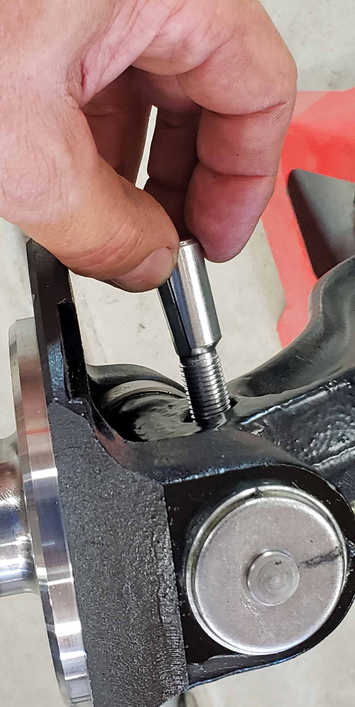
10 With the flat edge of the wedge-shaped lock pin facing the kingpin, install the pin from the front of the axle (so the threaded end points to the rear of the car) and tighten it with its nut.
Evenly tapping the bearing race into the 5×5.5 lug pattern wheel hub
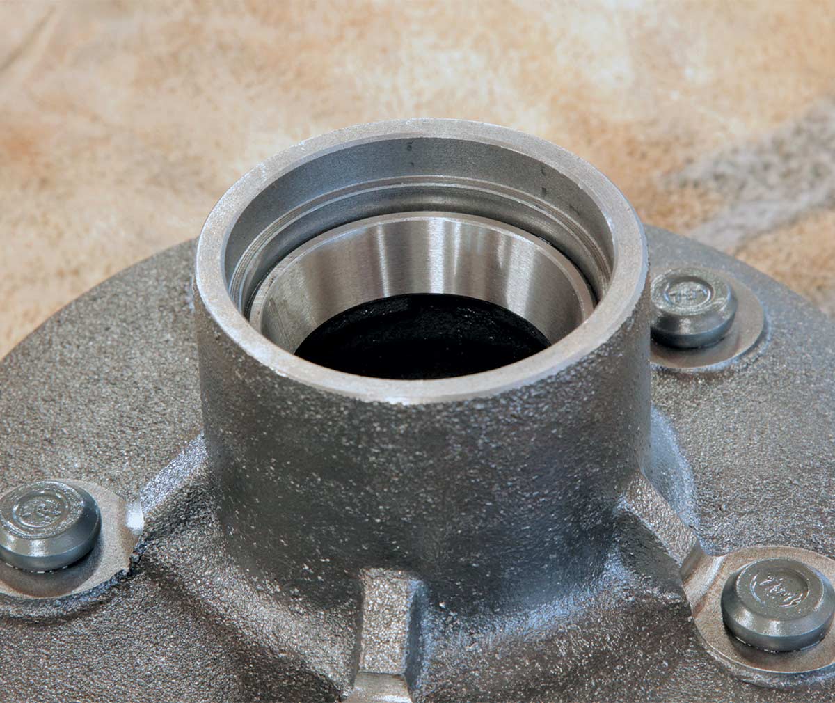
11 The easiest way to evenly tap the bearing race into the 5×5.5 lug pattern wheel hub (PN 91065450) is with a section of like-sized pipe and, once in place, should fit well into the spindle.
Placing inner bearing in first
The bearing being held in place with a seal
Evenly tapped into place with a block of wood
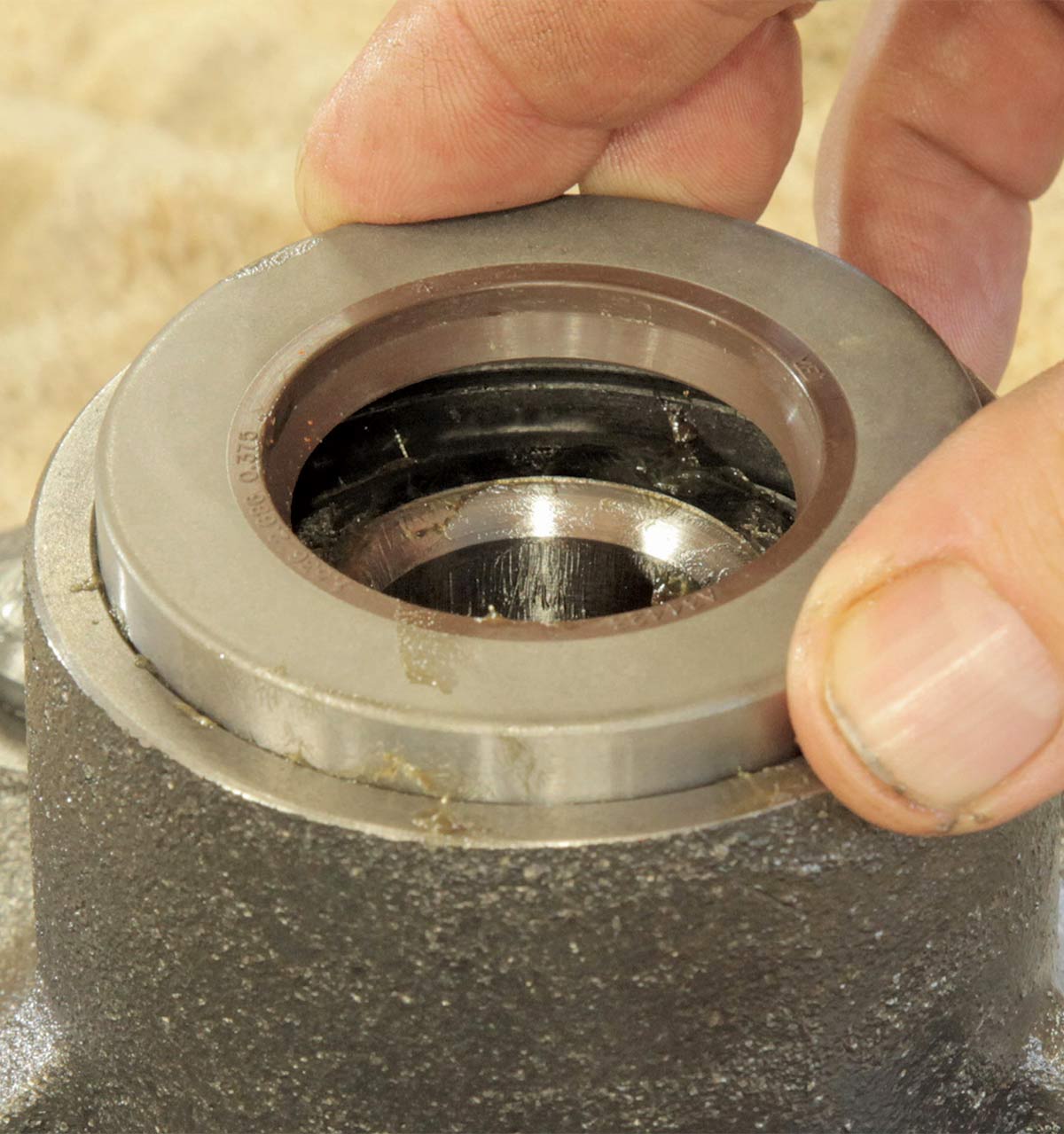
12 The inner bearing goes in first, then it’s held in place with a seal, which is evenly tapped into place with a block of wood.
Adding the anchor pin
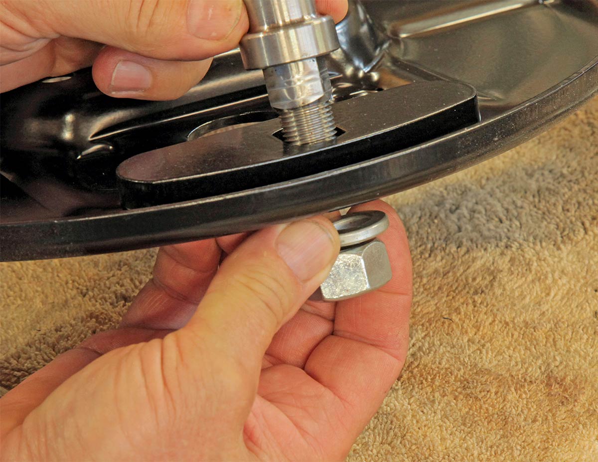
13 To start assembly of the brake parts, first add the anchor pin to the top of the backing plate, but leave it a little loose for now for assembly (but tighten when complete).
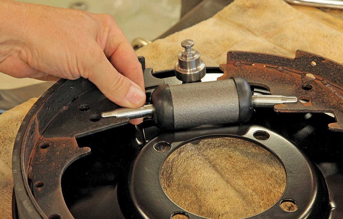
Attaching the wheel cylinders
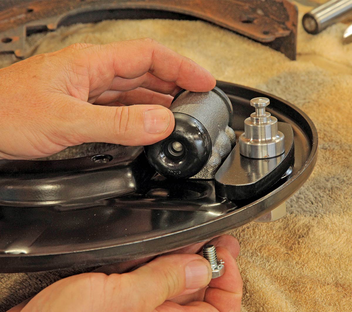
14 Next, the wheel cylinders are attached.
Comparing the two drum shoes
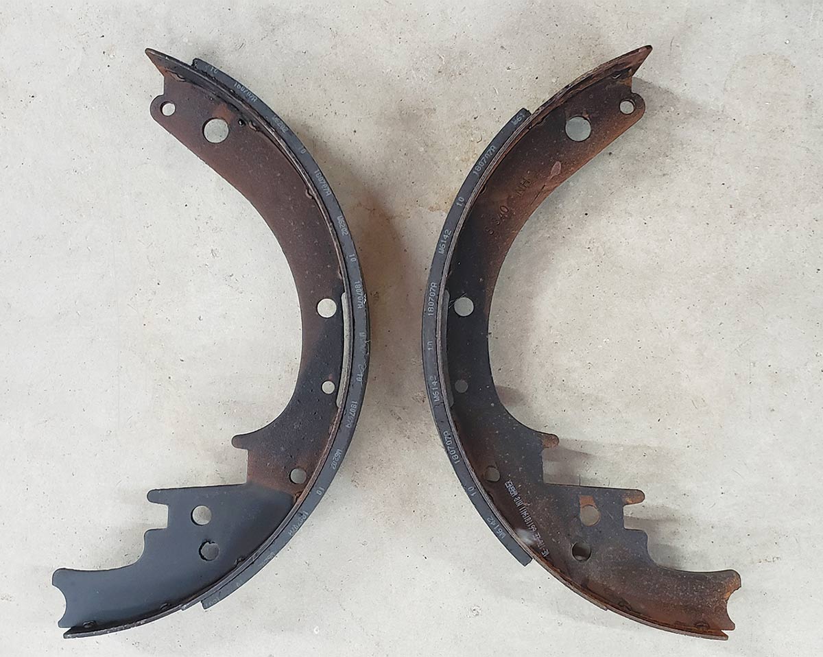
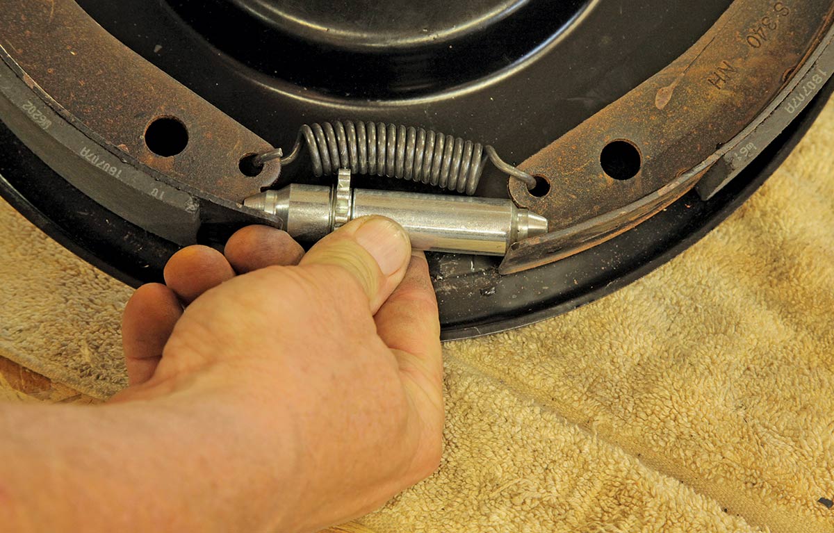
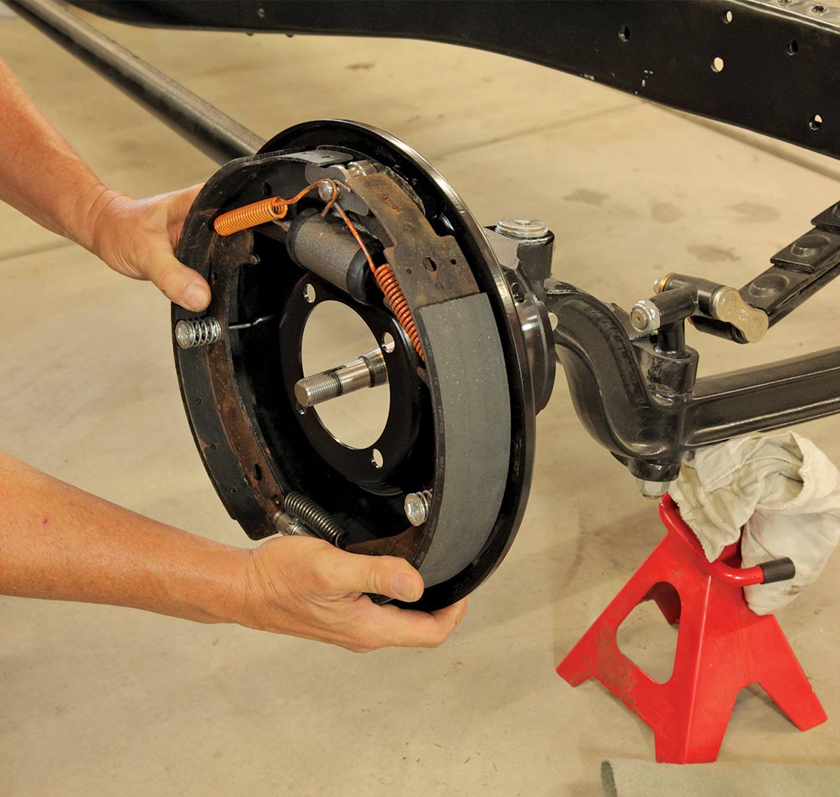
15 Comparing the two drum shoes, they’re identical in basic shape and holes except that one shoe has less brake material than the other. The one with less material faces the front of the vehicle, the longer material shoe faces the rear. Set both shoes in the backing plate and connect them with the short bottom spring.
Adding the brake shoe links
16 Next, add the brake shoe links, making sure they fit correctly into the wheel cylinder and on the larger of the two notches on the shoe.
Twist the ends of the star adjuster all the way
17 Twist the ends of the star adjuster all the way in before adding it under the bottom spring.
Attaching the retaining pins
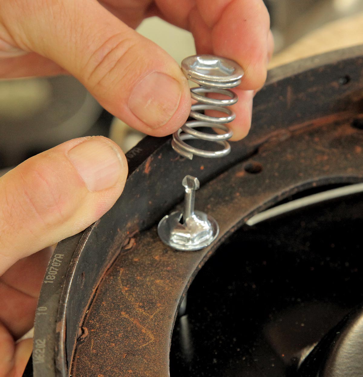
18 Two lengths of retaining pins are supplied (for 1.75- and 2-inch width shoes) so use the longer ones, placing your finger on the backside of the backing plate to hold the retaining pin in place. Then, while pushing the retaining spring and retaining cup down, twist it so it fits into tiny divots in the slotted cap, releasing it with the cap secured.
Seeing how the shoe retaining plate drops onto the anchor pin
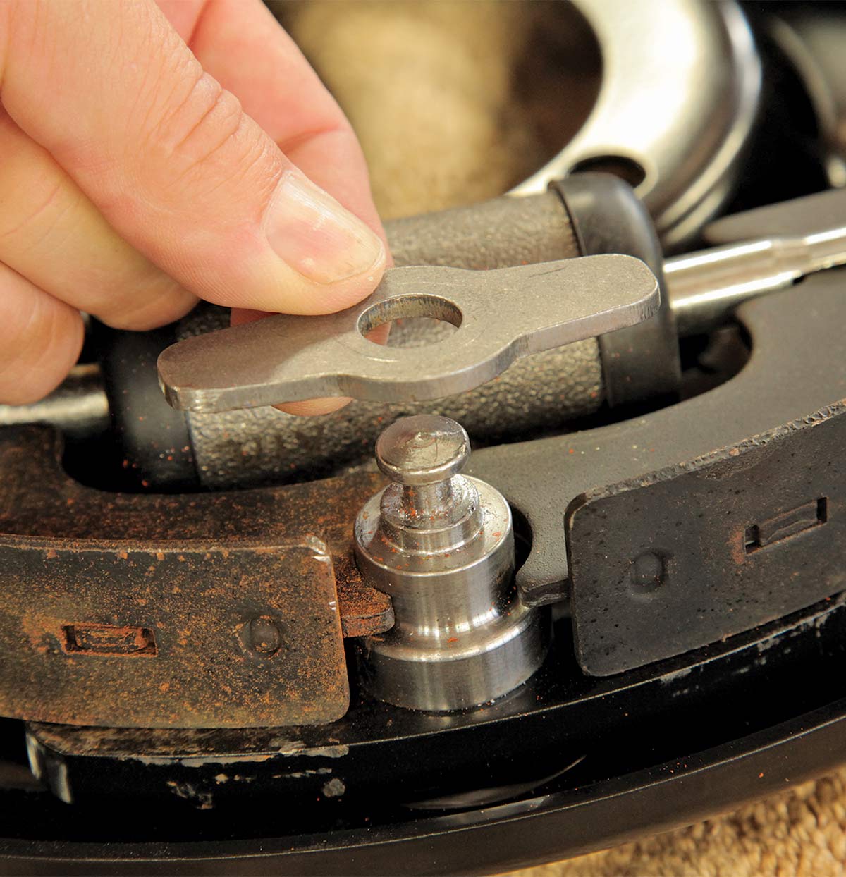
19 The shoe retaining plate drops onto the anchor pin, and will be held in place by a pair of orange springs.
Using the spring mounting tool to assist
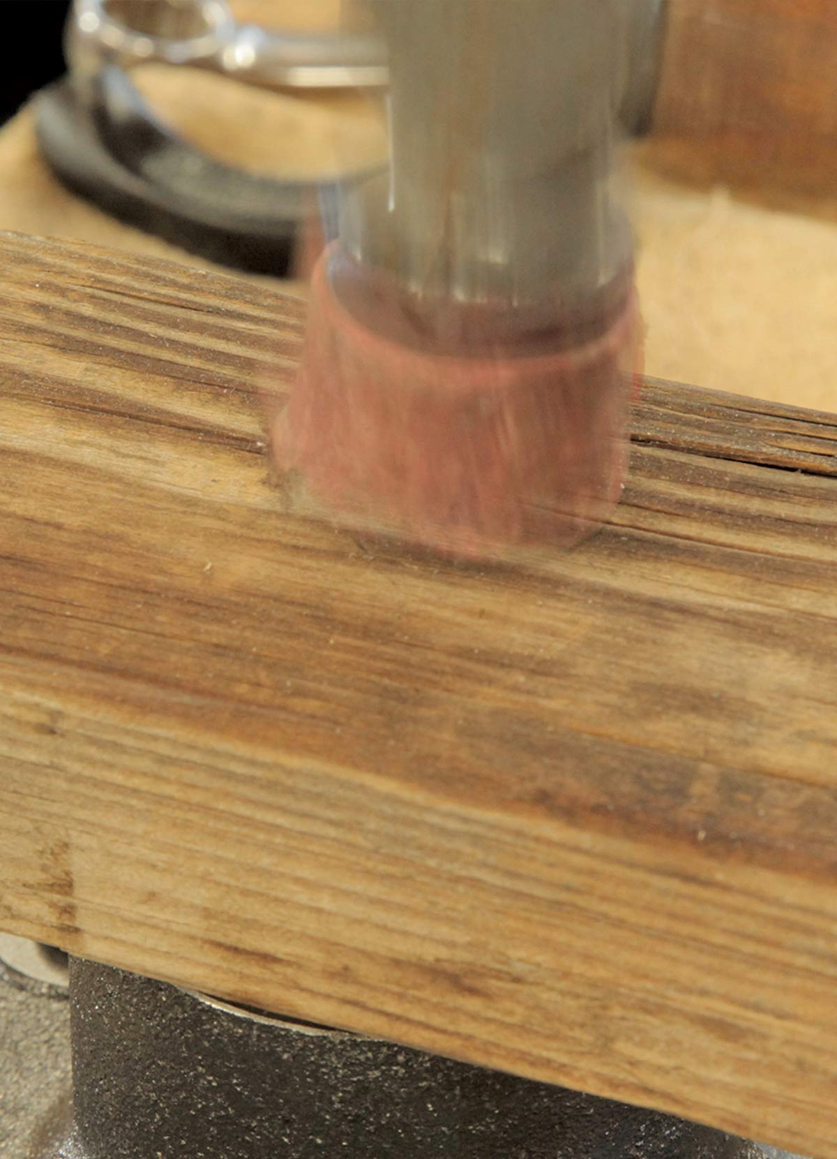
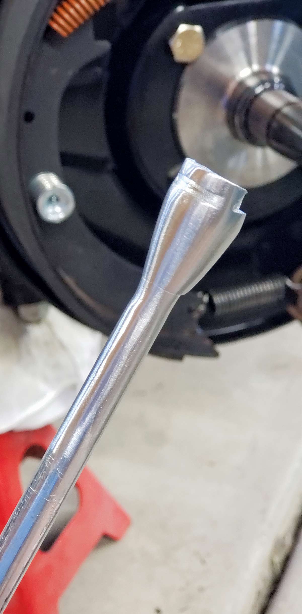
20 We bought this spring mounting tool at an auto parts store, then used a small air-driven sander and Scotch-Brite pads to grind, polish, and reduce the transition between the shaft and the head in order to make the spring slide easier during installation.
Fitting the orange return spring
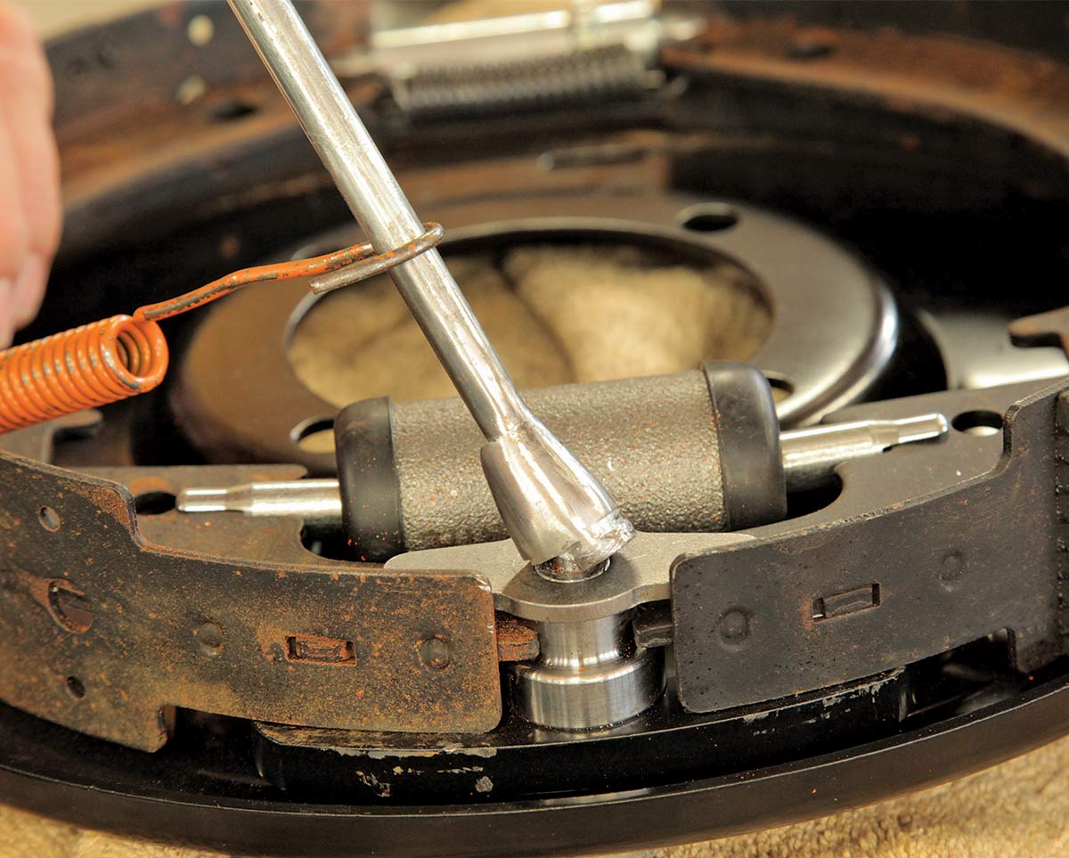
21 Fit the orange return spring to the shaft and the tool head over the anchor pin and, in one quick motion (like you’re speed-shifting from First to Second), the spring should slide off the tool and its horseshoe-shape end loop around the pin.
Looking at the assembled backing plate
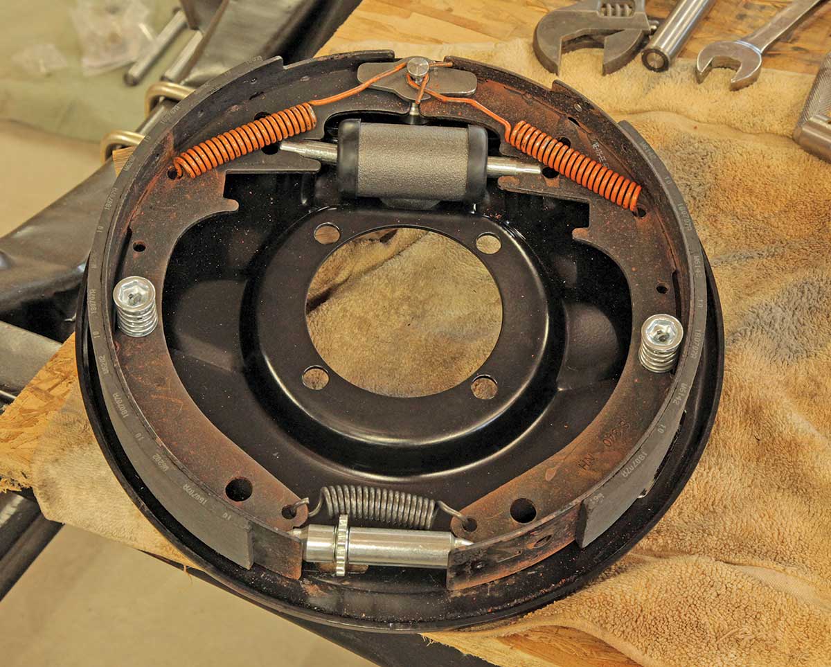
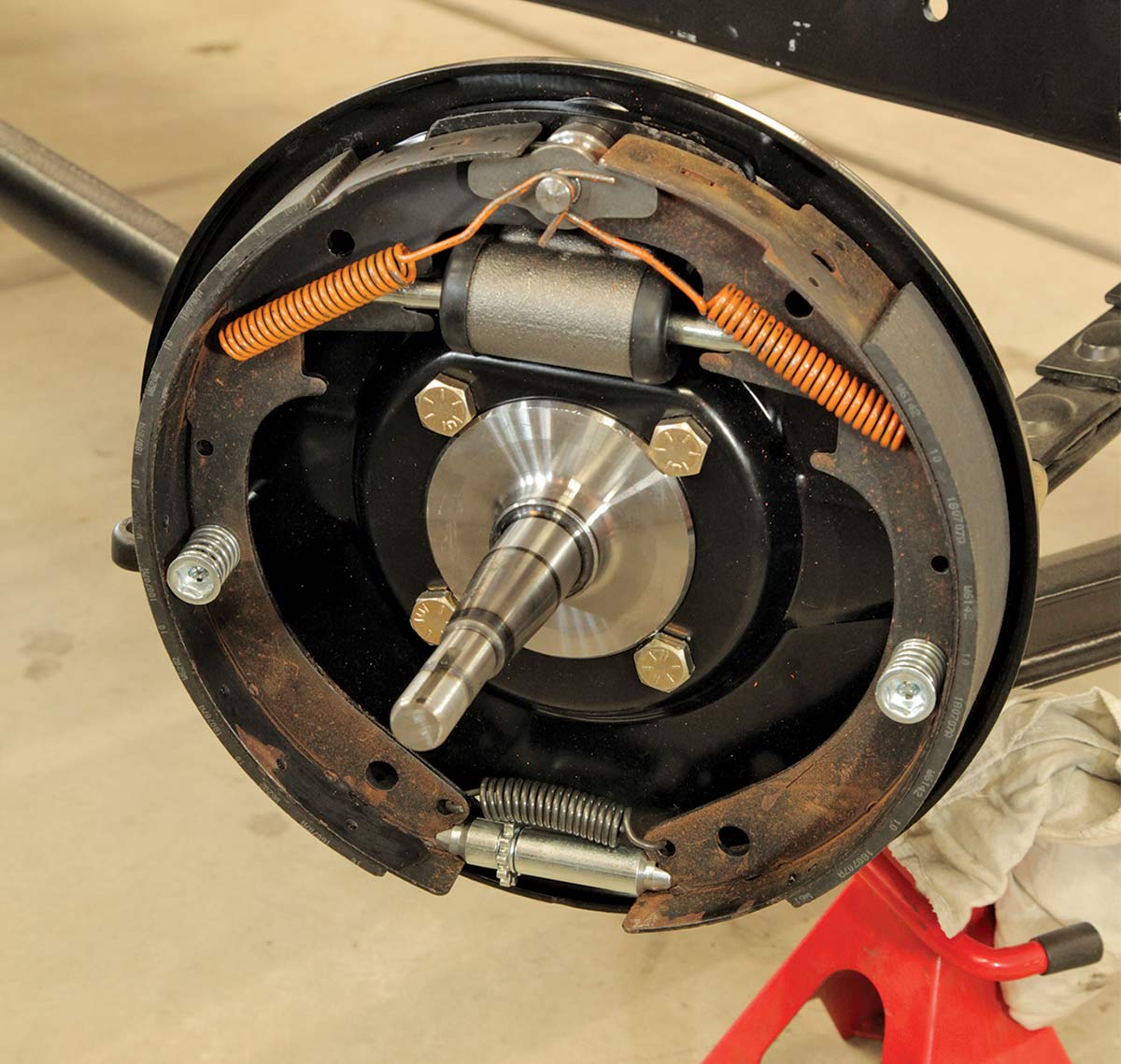
22 The assembled backing plate should look like this.
Attaching the assembled backing plate to the spindle
23 Now attach the assembled backing plate to the spindle using just the upper two bolts for now.
The painted Super Bell steering arms
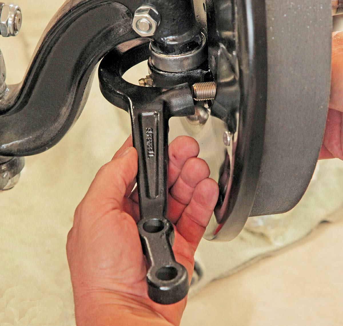
24 The bottom two bolts that hold the backing plate to the spindle also secures the painted Super Bell steering arms, with two-hole arm (if you have cross-steer) for the passenger side, and the one-hole on the driver side.
Looking at the completely assembled brake system on the spindle
25 Here is the completely assembled brake system on the spindle.
Showing the inspection/access plug
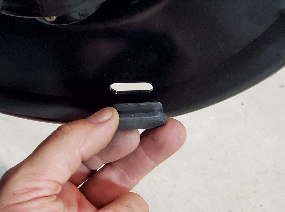
26 Don’t forget the inspection/access plug!
Popping the wheel hub on
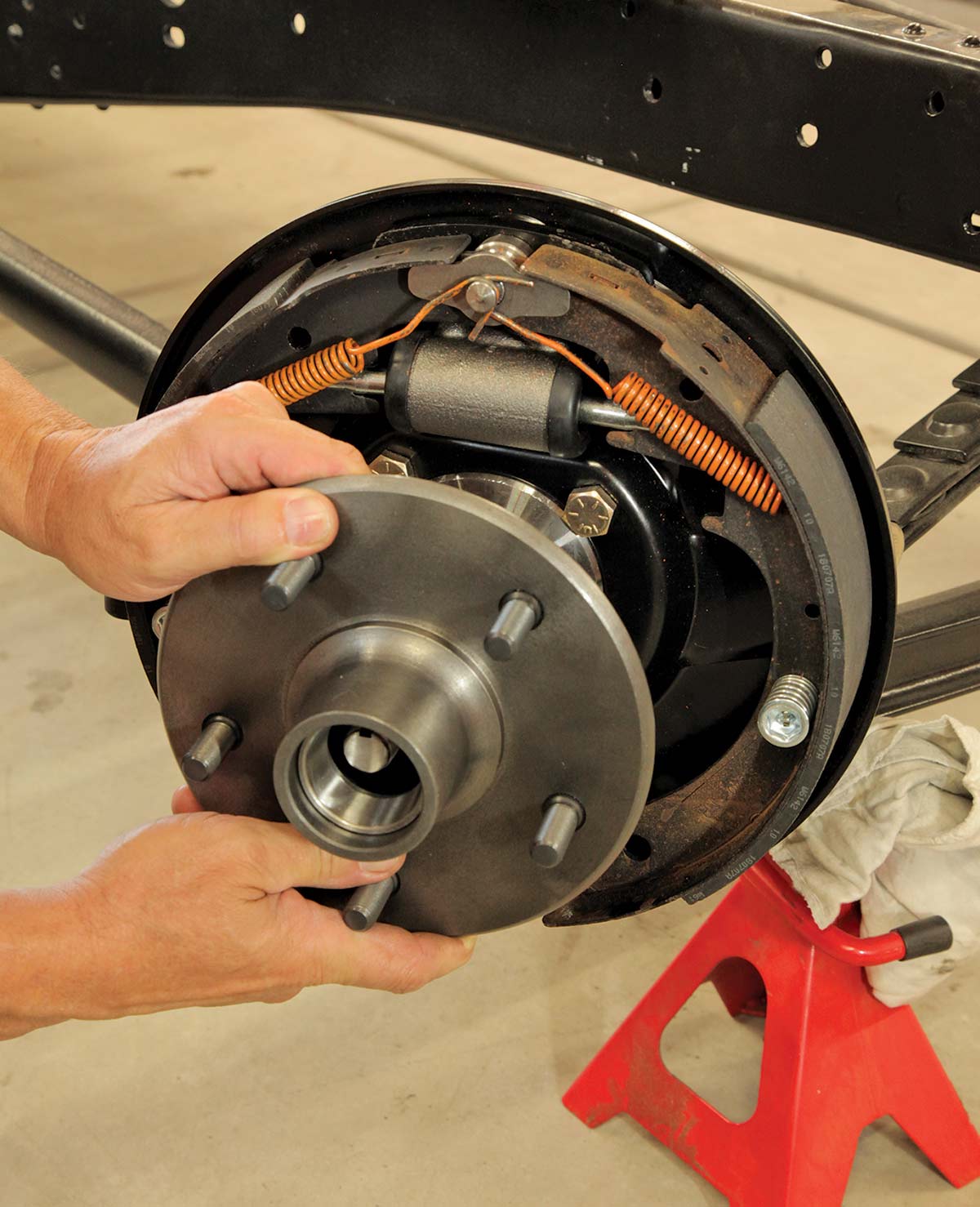
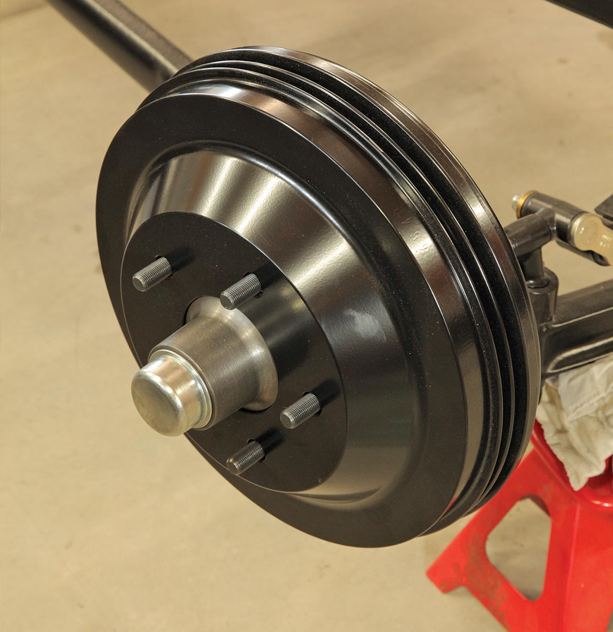
27 With the inner wheel bearing and seal already in place on the hub, now just pop the wheel hub on.
Adding the outer bearing and lock washer
Adding the castle nut
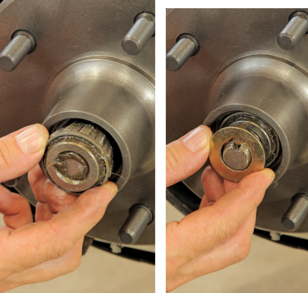
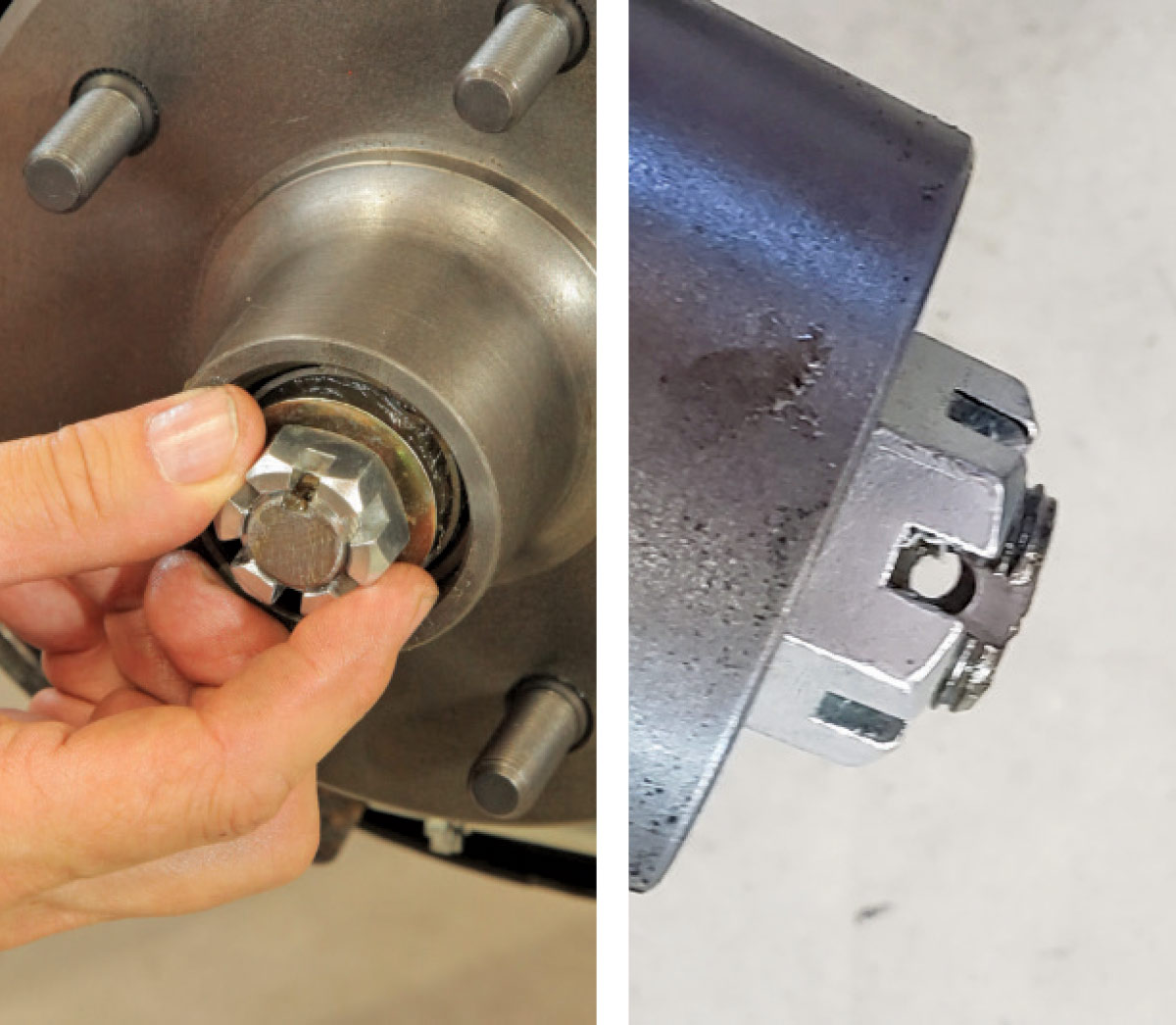
28 Add the outer bearing, lock washer, castle nut, and tighten it enough so the hub rotates but doesn’t wiggle on the spindle. And make sure the hole in the spindle’s threaded end lines up with a gap in the nut for the cotter pin.
Add the cotter pin
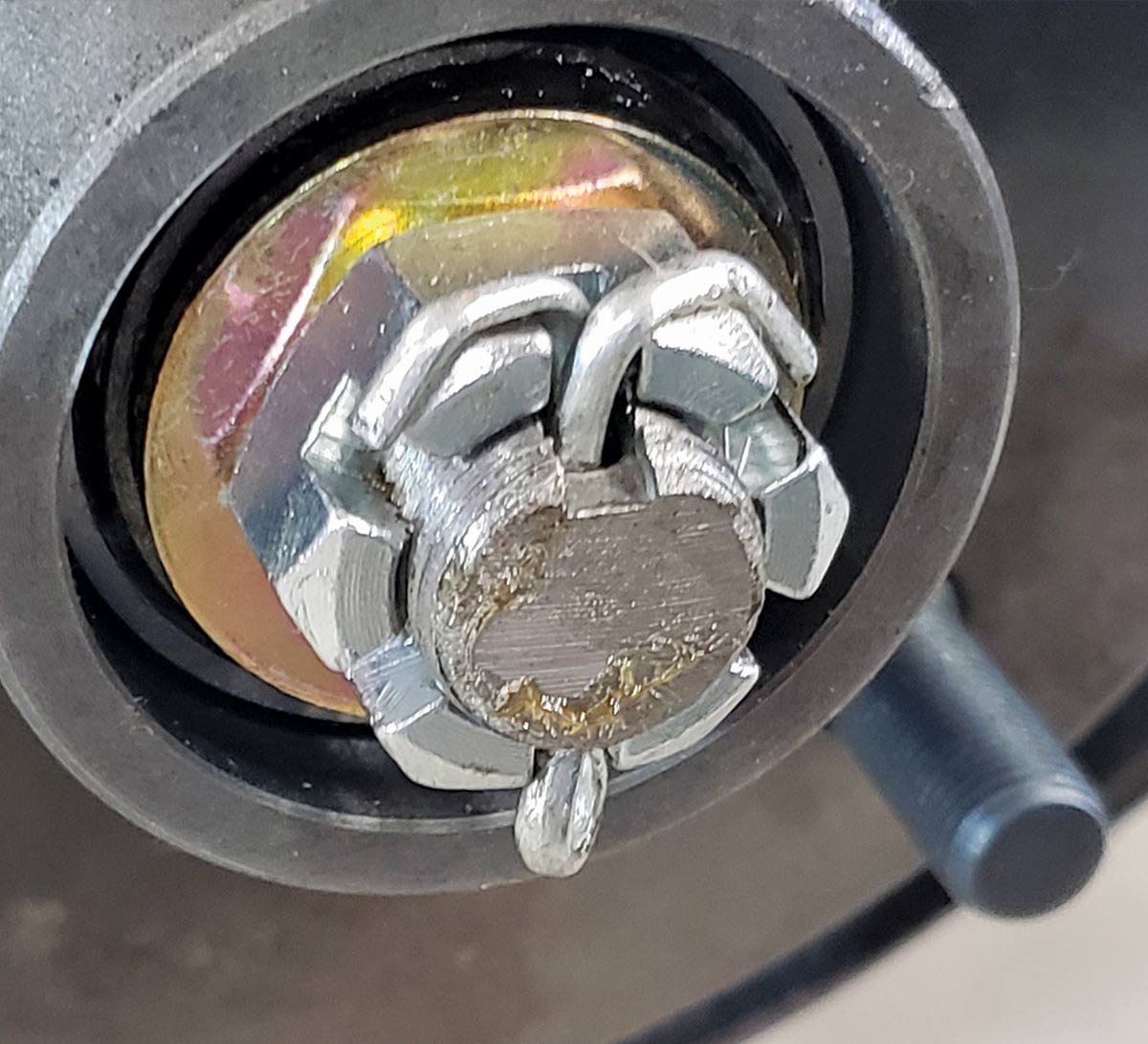
29 Add the cotter pin and bend the ends over to secure the castle nut.
Install the Lincoln drum
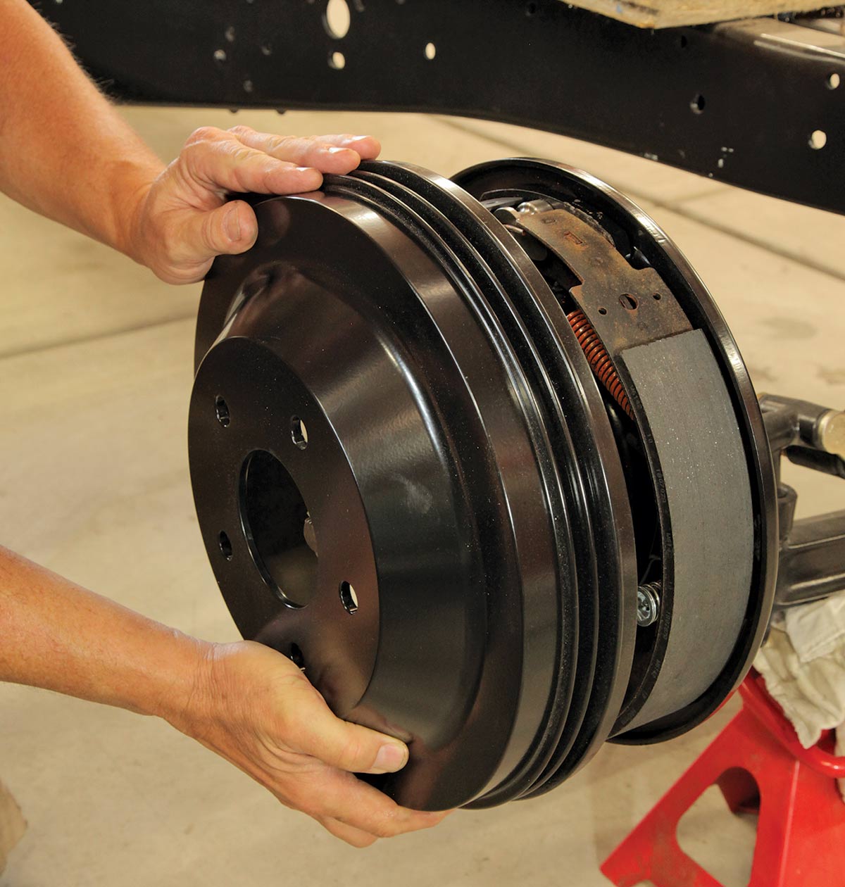
30 Install the Lincoln drum (and make sure the shoes are adjusted “in” so it slides on easily).
Bolting the Lincoln drum with the factory 17-inch wire wheels
31 The drum will be held in place once the factory 17-inch wire wheels are bolted up.
Looking at the assembly
Add the tie rods to the steering’s drag link
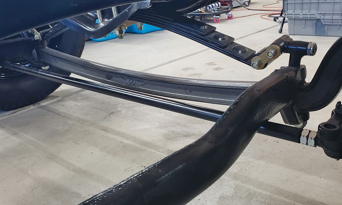
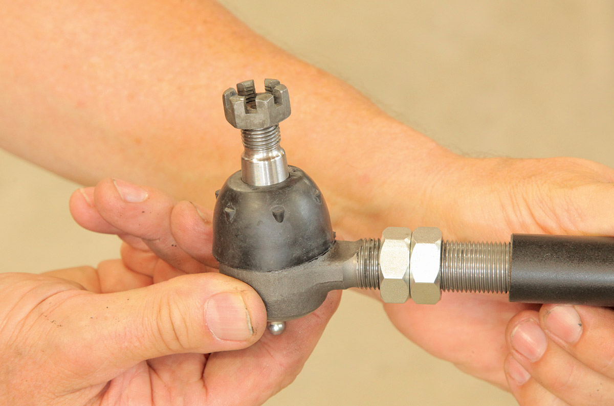
32 All that’s left is to add the tie rods to the steering’s drag link. Remember one has reverse threads so you can easily adjust the toe without having to remove the assembly.
The wheels on the frame
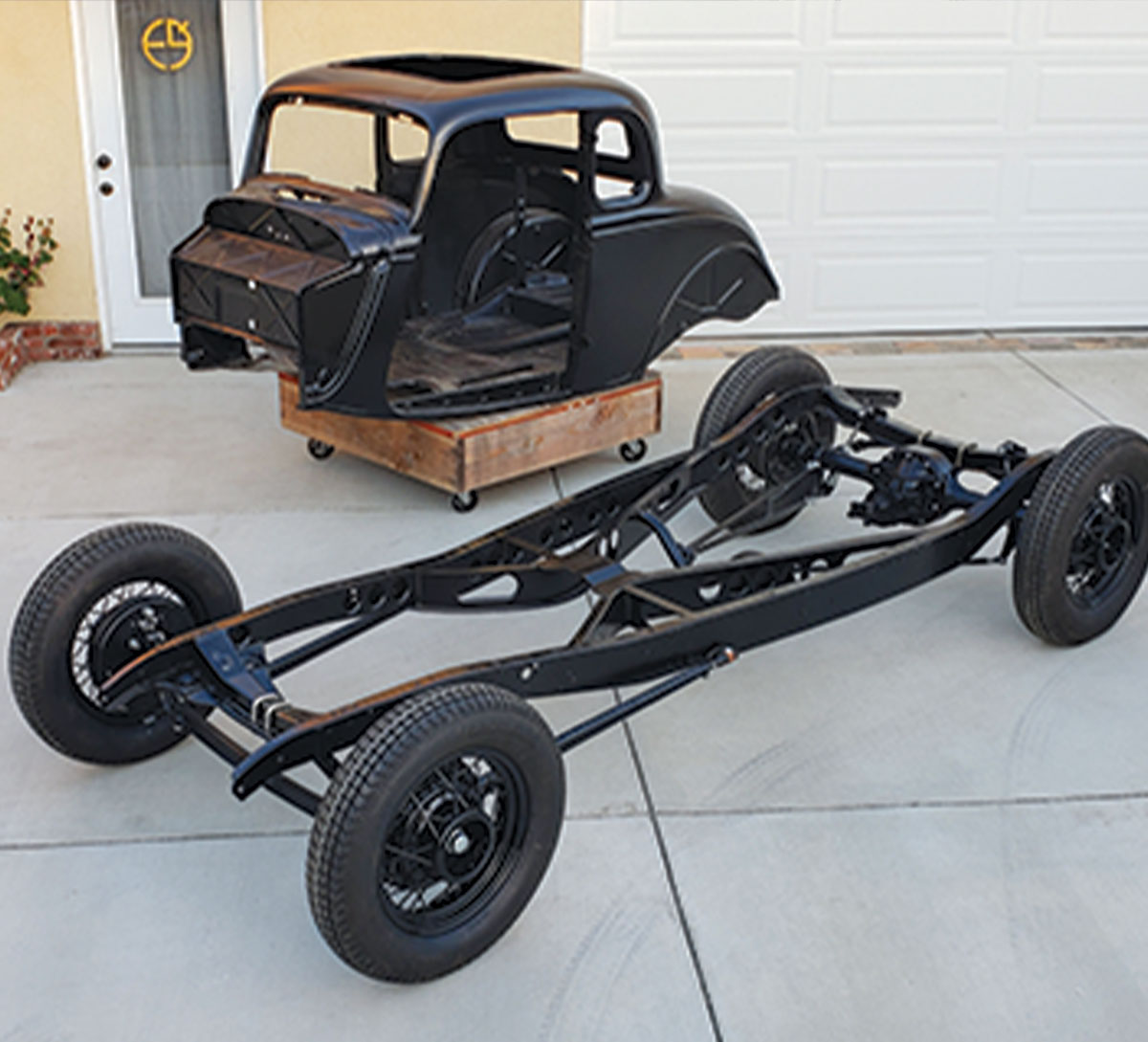
33 Now the wheels can go on and the body is next!
Modern Rodding | July/August 2020