Modern Rodding Tech
InTheGarageMedia.com
Modern Rodding Tech
InTheGarageMedia.com
3/4 view of a green '30 Ford sedan
1. To see the full feature of this Model A sedan, make sure to check the Nov. ’23 issue.
Building an Amazing ’30 Ford Channeled Sedan
Part 1: Chassis & Flooring
By Ron Covell Photography by Chris Gray Illustration By Eric Black/eBDCo
G

erry Kerna is an avid gearhead with an eclectic collection of outstanding cars. She, yes, Ms. Kerna, wanted to build a state-of-the-art Model A sedan in the mildly channeled style and when she found a suitable ’30 Ford sedan body, the project commenced.

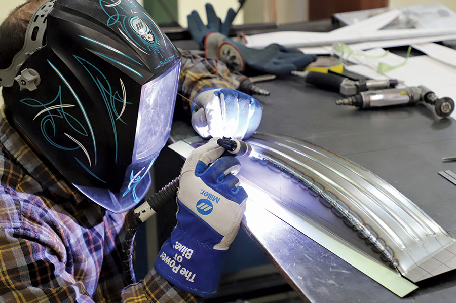
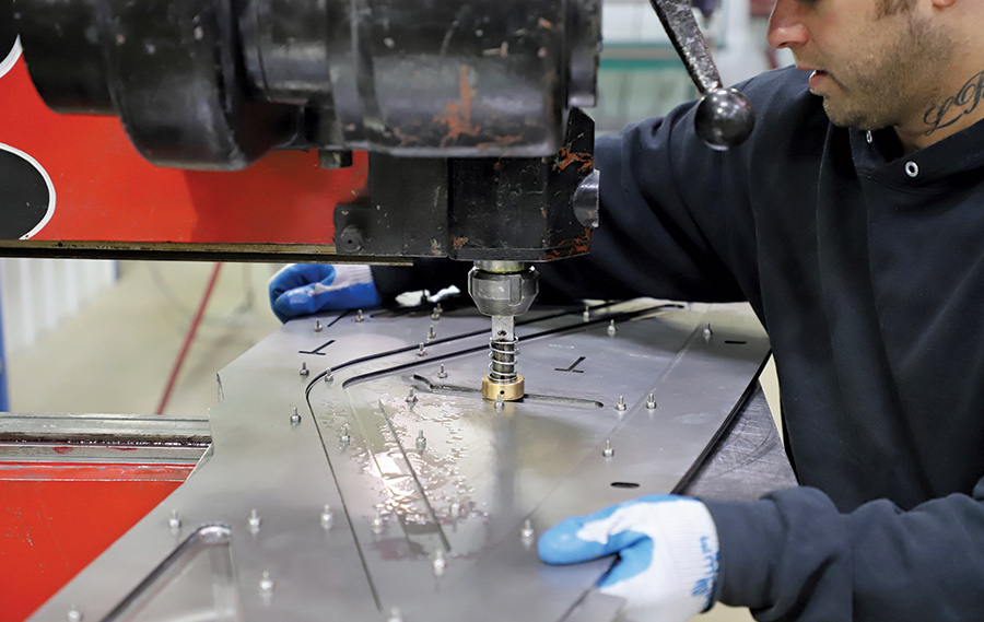
Cornfield Customs chopped the top 4-1/4 inches and then sent it to Roadster Shop to have the chassis built, along with an extensive list of body modifications. This car has so much special work that it will take a several-part series to cover the project in sufficient depth. Mark Giambalvo of Creative Rod and Kustom was charged with the final build and assembly.

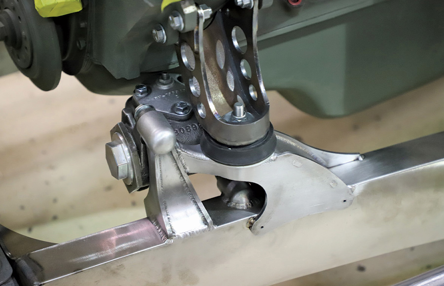
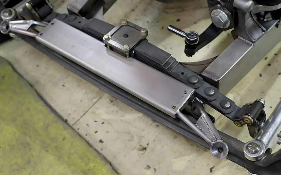
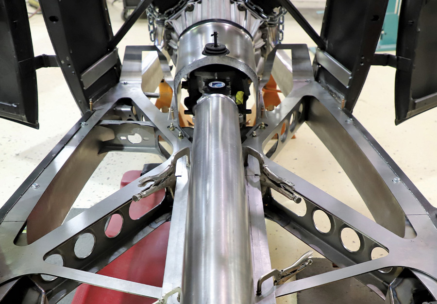
Roadster Shop is well attuned to cars of this period, and they went to great lengths to give it a traditional look while incorporating the latest technology and build techniques. The frame is completely custom designed. It looks similar to a ’32 Ford frame but there were many modifications needed to work with the Model A body and have the aggressive, low stance Kerna wanted. The profile of the frame was made to follow the contours of the A-body, and the ’rails were pinched to match the width of the ’32 Ford grille shell. A special, super-low front crossmember was designed to allow the frame to flow forward from the firewall without a kick-up, which is an awkward-looking modification often used to get cars this low.

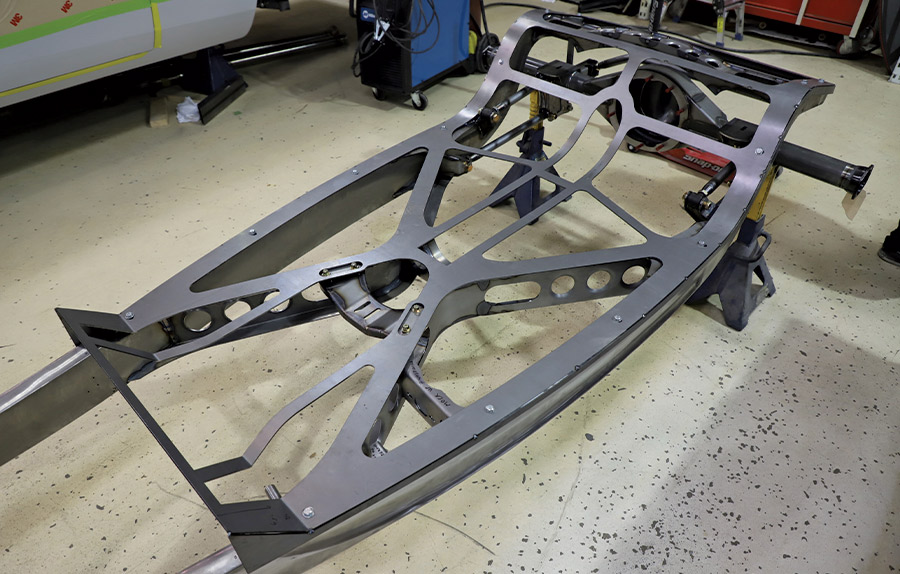
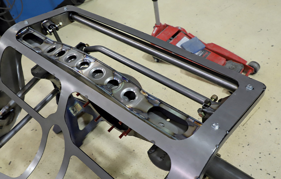
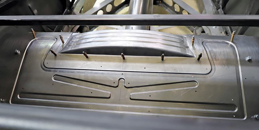
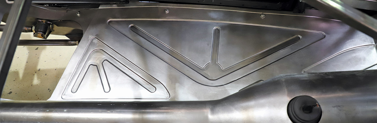
The rear of the frame was kicked up 8 inches to clear the rear axle. This was done as a gracefully sweeping curve rather than using an angular Z-shape. A beefy X-member was added to the frame, substantially increasing the stiffness.

The iconic reveal embossed on the side of a ’32 frame was repositioned, starting precisely at the firewall and ending in line with the rear wheelwell bead. The wheelbase was stretched to 107-1/2 inches, 4-1/2 inches longer than a Model A. The body was slightly channeled over the frame in the manner of a ’32 Ford.

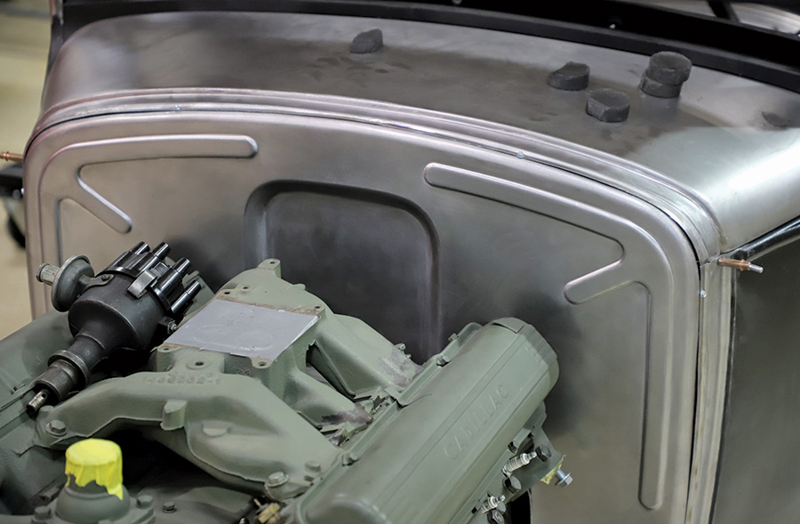
The engine is a ’56 Cadillac V-8, which is perfect for the vintage style of the sedan. Watch for more articles detailing the exceptional work done on this car. (The Model A sedan appeared on the cover of the Nov. ’23 issue of Modern Rodding, and inside is the full feature.)

illustration of a '30 Ford sedan by Eric Black
2. Eric Black did the artwork that helped get this project off to a great start.
CAD model of the chassis
3. Roadster Shop did a full CAD design of the chassis, using styling cues from a ’32 Ford, keeping it low to the ground and carefully matching the contours of the Model A body.
closeup of the front<br />
crossmember
4. The front crossmember uses a unique underslung design, cradling the POSIES Super Slide Spring from the bottom.
closeup of the motor mounts
5. The motor mounts are completely unique, and on the driver side the steering box mount is integrated with the design.
steering arm
6. Because the framerails are so low to the ground, the steering tie rod runs above the frame. Special steering arms were machined from billet chromoly to position the tie rod at the correct height.
view of the steering linkage
7. With the front suspension assembled, you can see how the steering linkage works. The draglink runs below the tie rod to its own steering arm, and the frame is notched on the passenger side for clearance.
clever mount attached to the front of the frame
8. A clever mount attaches to the front of the frame, providing a platform to support the radiator. The tubular extensions on each side are the headlight mounts.
view of the components after radiator has been mounted
9. With the radiator mounted, you can see how efficiently the components fit together.
X-member on the chassis
10. The chassis was built with a beefy X-member, providing torsional stiffness. A platform perfectly matches the contours of the frame, which will become a structural part of the body.
rearend showing the inner body structure
11. The Strange 9-inch rearend has a four-bar system and a sturdy Panhard bar. The one-piece, laser-cut 10-gauge inner body structure is clearly visible here.
person wearing a welding helmet working on a piece of the sheetmetal cover
12. A special sheetmetal cover was fabricated to cover the arched rear crossmember, which provides clearance for the third member. Airbags will suspend the rear of the car.
sheetmetal cover over the transmission
13. A snugly fitted sheetmetal cover was made to cover the TKO five-speed TREMEC transmission.
view of the one-piece cover being used to cover the drive-shaft
14. A one-piece cover was made to hug the driveshaft. Everything was sized to give adequate clearance but maximize space inside the body.
a transition piece
15. A transition piece was made to connect the transmission cover to the driveshaft cover. All the seams will be TIG welded and metal finished.
view of how the driveshaft and transmission cover the body sub-structure
16. Here, you can see how the driveshaft and transmission cover mate to the body substructure.
pieces of metal cut out
17. Elaborate, laser-cut metal guides were made for the intricate embossing applied to the floor and firewall panels.
Pullmax machine being used to create custom guides on the floor panels
18. Here, a Pullmax machine is used with the custom guides to form the detailing on one of the floor panels.
rear body floor panel
19. This is the rear body floor panel. You can see how superbly the guides work to make the stepped and embossed designs.
three-element design theme on one of the larger floor panels
20. One of the larger floor panels is fitted into place here. Note how the graceful three-element design theme is repeated on these panels.
overview off the floor panels inside the body
21. Here is an overview showing how the floor panels fit inside the body. This kind of detailing takes time, but it helps to eliminate drumming and vibration inside the car.
new metal firewall being worked over with a hammerform
22. A new metal firewall is being flanged by working over a hammerform. A mechanical shrinker was used on the tightly radiused corners.
firewall with embossed designs
23. The firewall is shown a little farther along, featuring the embossed designs and the recess for the distributor.
view of the cowl top
24. The cowl top was removed and smoothed and is being carefully fitted before welding it back in place. Next time, we’ll look at more extensive body modifications.
SOURCE
Modern Rodding
VOLUME 5 • ISSUE 46 • 2024