Modern Rodding Tech
InTheGarageMedia.com
The original 1936 Ford gas cap was housed in the driver side taillight. Unfortunately, those gennie lights were not slick enough for our postwar custom look.
Fill ’Er
UP
Part 2: Fresh Fuel From Filler to Flathead
By Gerry Burger Photography by the Author
R

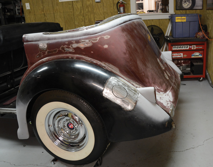
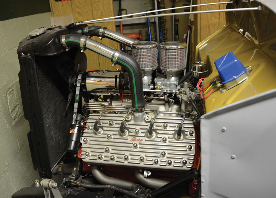
ecently we set about removing the old fuel tank and installing a new Tanks Inc. fuel tank in our 1936 Ford phaeton. The removal of the old gas tank and installation of the new unit went as expected. When we last left you, we had a brand-new fuel tank and no way to get gasoline into said tank. All of this is part of our postwar custom approach to the car with no spare tire, custom split bumpers, no top (Carson Top may come later), and 1940 Packard taillights. The original 1936 Ford gas cap extends up through the driver side taillight. Clever in its day, but when the taillights left so did the fill cap.

We figured there were two basic choices: a simple stock-style gas cap and grommet protruding through the fender or we weld in a gas-fill door. After working this hard to slick the rear of the car, the last thing we wanted was a gas cap sticking out of the fender.

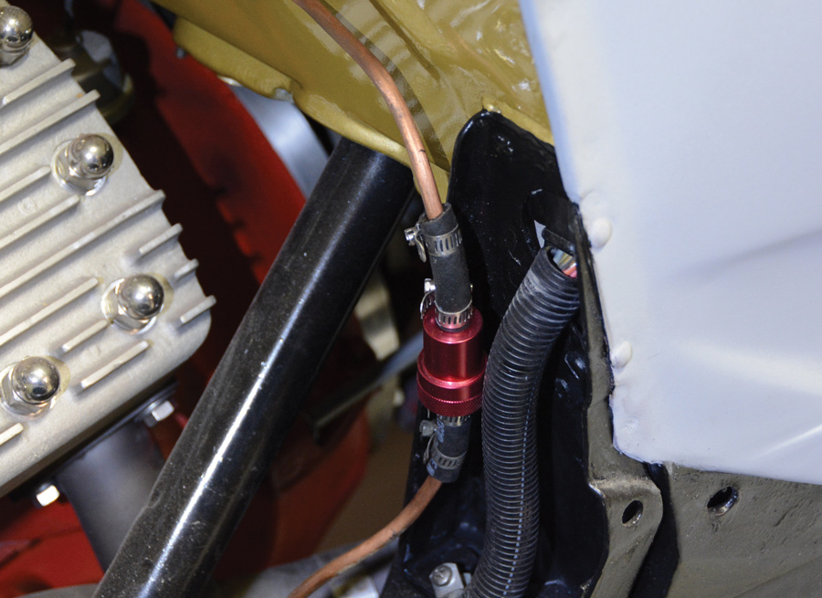
After installing a Classic Instruments fuel gauge sending unit, the tank bolted in as a direct replacement with a simple piece of rubber fuel line connecting to our existing fuel line on the car. Before we go any further, we want to remind you, if you are working around any gas tank, please exercise the utmost caution. Grinding and welding can ignite fumes.

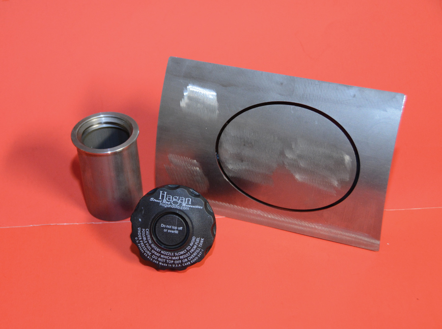
We spent a little time perusing the Speedway Motors website and discovered their full assortment of Hagan gas-fill doors. Different shapes and fill angles made the choice a bit involved, but there is ample information on the Speedway website to get it right. There were three basic shapes of filler doors: square, round, and oval. Square was definitely not right on our round fender, round would be OK but in the end we opted for the oval-shaped door as we felt it most-resembled a gas door found on a ’50s car, much like an early customizer may have used. Decision one complete. Oval door.

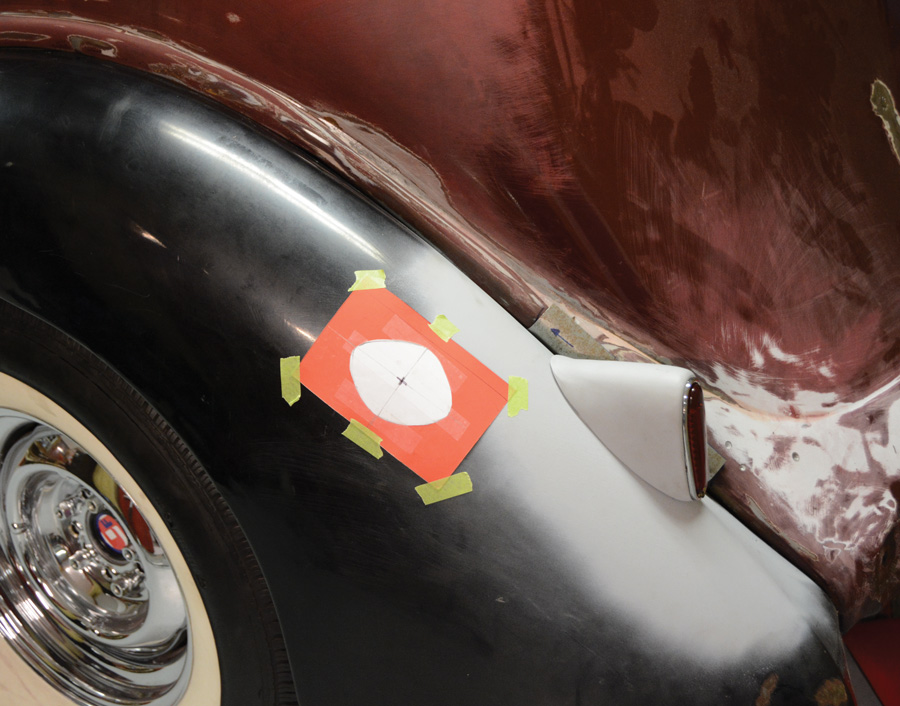
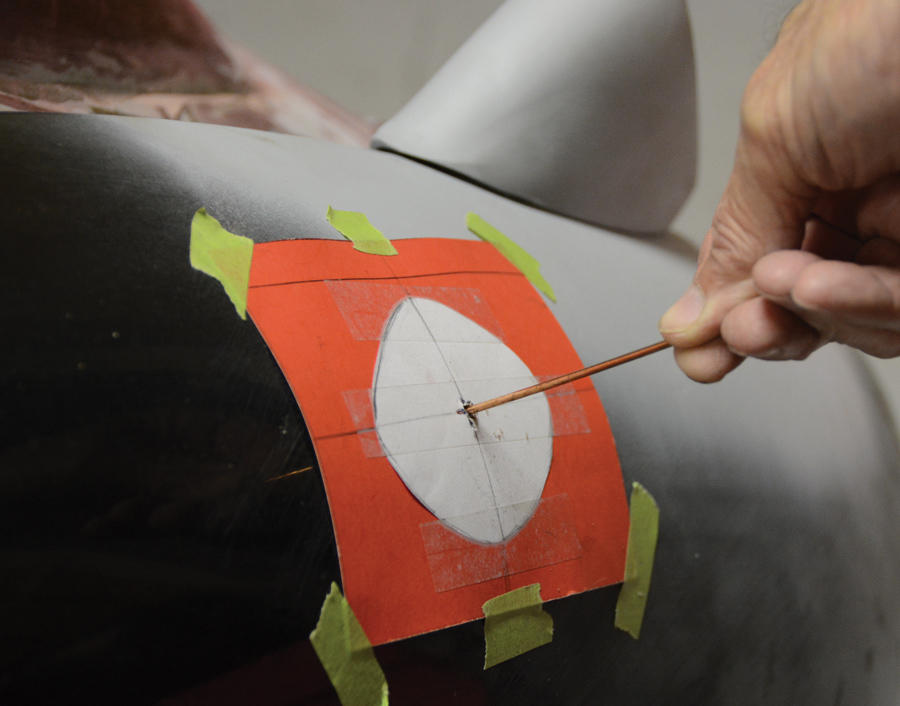
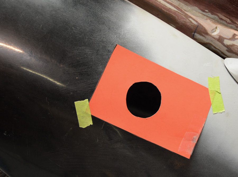
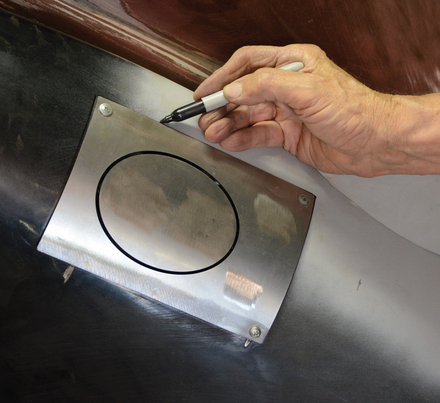
Next, we had to locate the fill door on the fender. We did this before we ordered the part. With a simple poster board template we taped the shape to the fender, finding a location where it would be well above the gas tank and also look “factory” in the fender. Satisfied with our location we drilled a 1/8-inch pilot hole in the center of our hand-drawn oval. We passed a welding rod through the hole to give us an idea of what would be required to connect the filler to the tank.

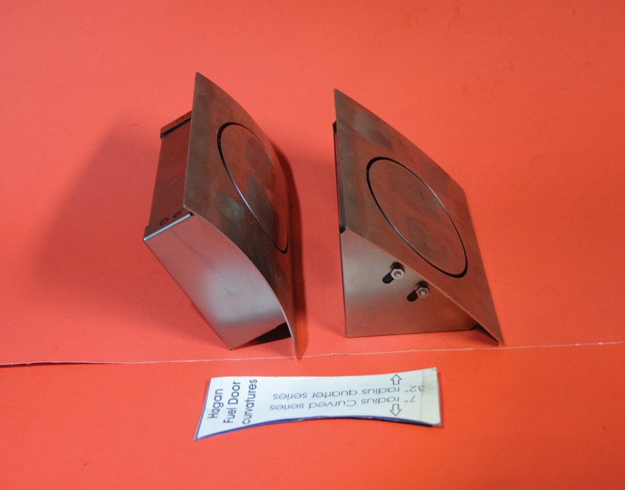
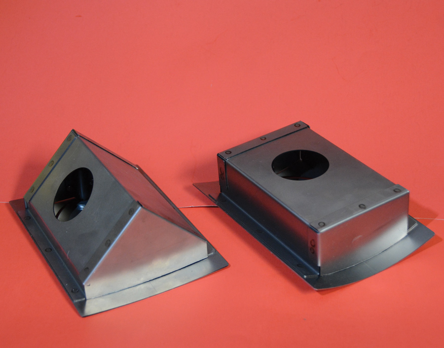
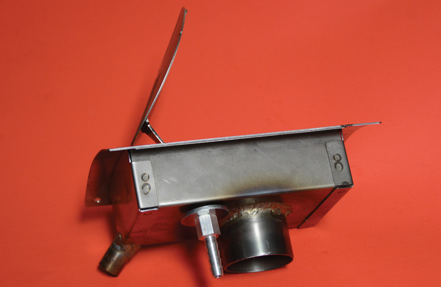
There are two different fill boxes, one has the fill neck going straight out the back, while the other points the fill neck down on a 45-degree angle. Our welding rod indicated we should be able to fabricate a smooth-flowing fill pipe using a straight box. That will keep everything rolling downhill for a smooth fill.

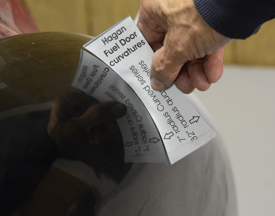
The final decision was choosing the proper contour of the fill box to best fit our fender. There are two different contours offered, one is a 7-inch radius and the other is a 32-inch radius. A template was printed out from the Speedway website and carefully cut out on poster board. This contour template was then held in place where the fill door was to be located. In our case the 7-inch radius was a perfect fit. The order was placed for an oval door, 7-inch radius, straight fill gas door.

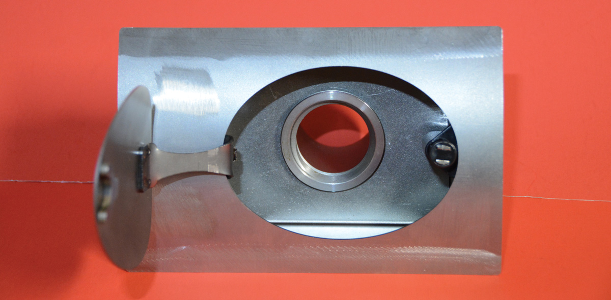
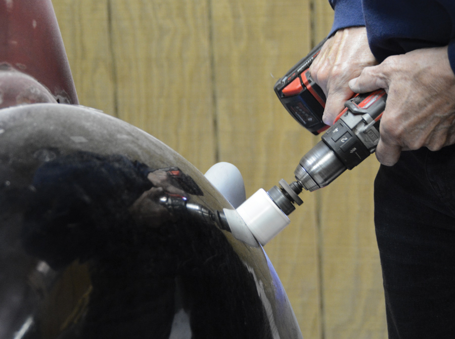
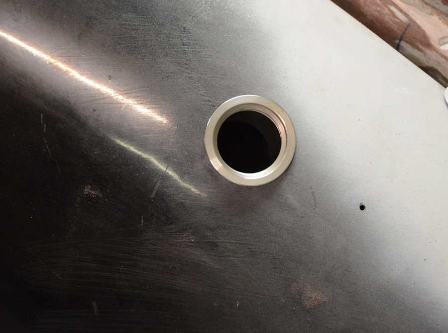
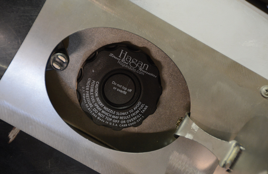
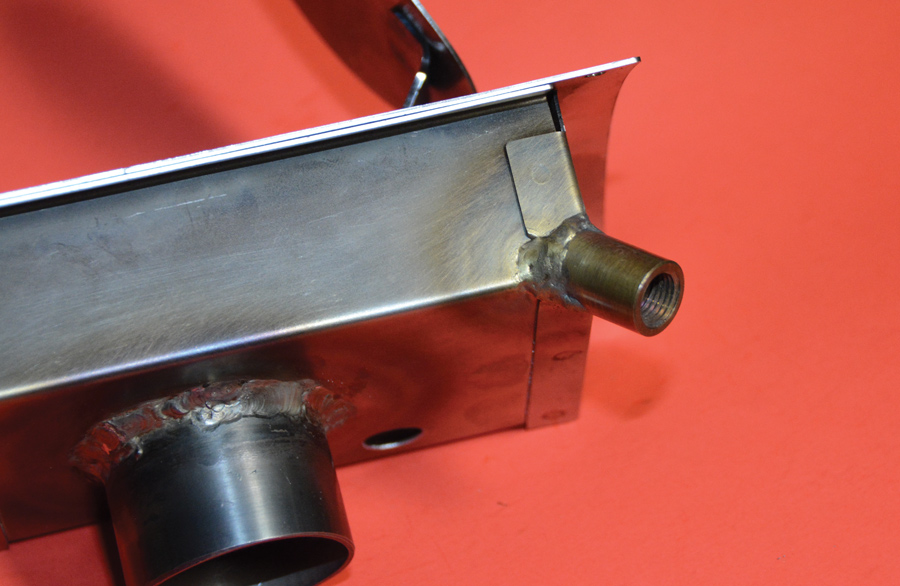
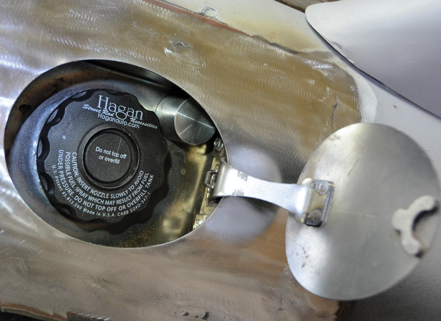
The gas-fill door kit comes with the actual fill neck separate from the door assembly. This worked out well. Using our 1/8-hole for center we determined where the fill neck would pass through the fender. A 2-inch hole saw provided the opening for the fill neck. With the fill neck passing through the fender, we were able to check the connection routing from the fill neck to the gas tank. Satisfied this connection could be made we made a template, marked the fender, and cut the opening, allowing the fuel fill box to protrude through the fender. Now it was time to weld the fill tube into the fill box. Being a bit on the OCD side, we wanted the writing on the gas cap to be straight when you opened the fill door. Since it is a “fill-through” cap it would not be removed. We installed the cap in the fill neck and marked the neck and the fill box to properly orientate the writing on the cap. We then removed the plastic cap and welded the fill neck into the box. Be certain to remove the magnetic latch in the fill door prior to any welding. We also drilled a hole in the back of the box for our fuel tank vent fitting, you may not need this in your application. Finally, we cut a hole in the lowest corner of the fuel fill box and welded a 1/4-inch pipe coupling in place to act as a drain for the box.

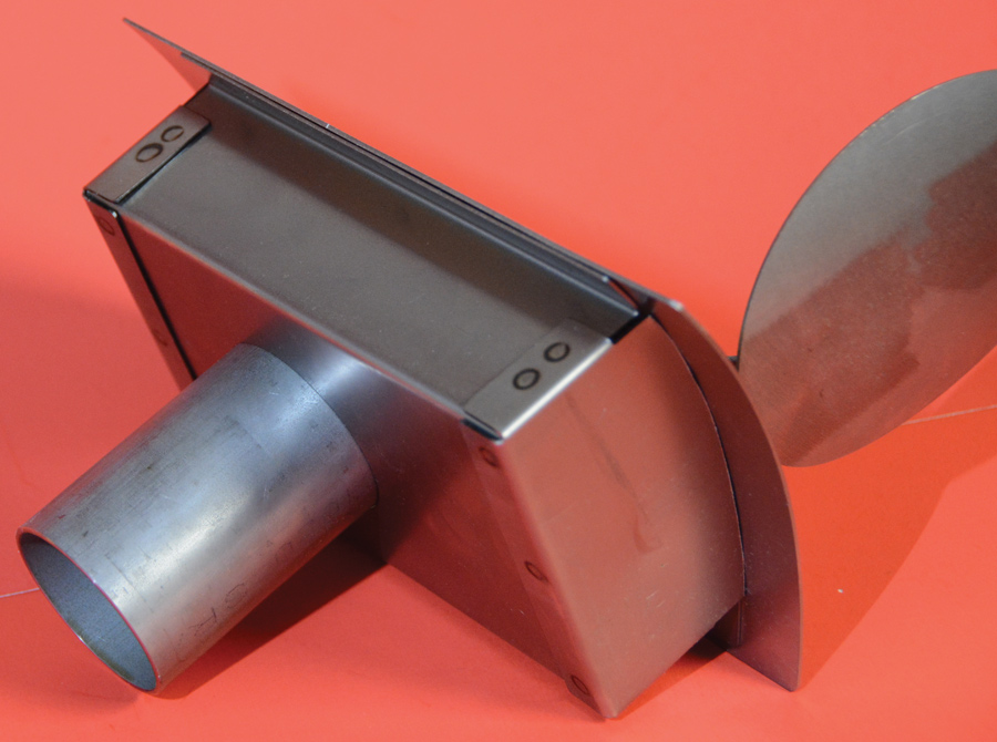
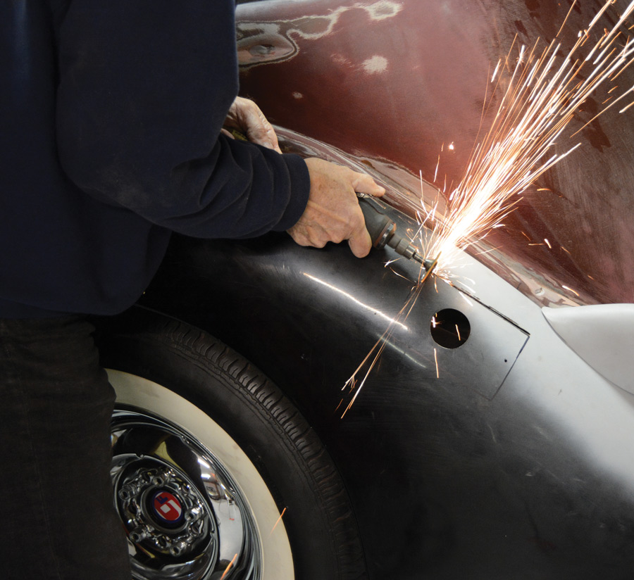
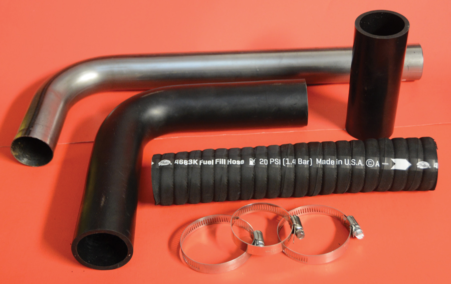
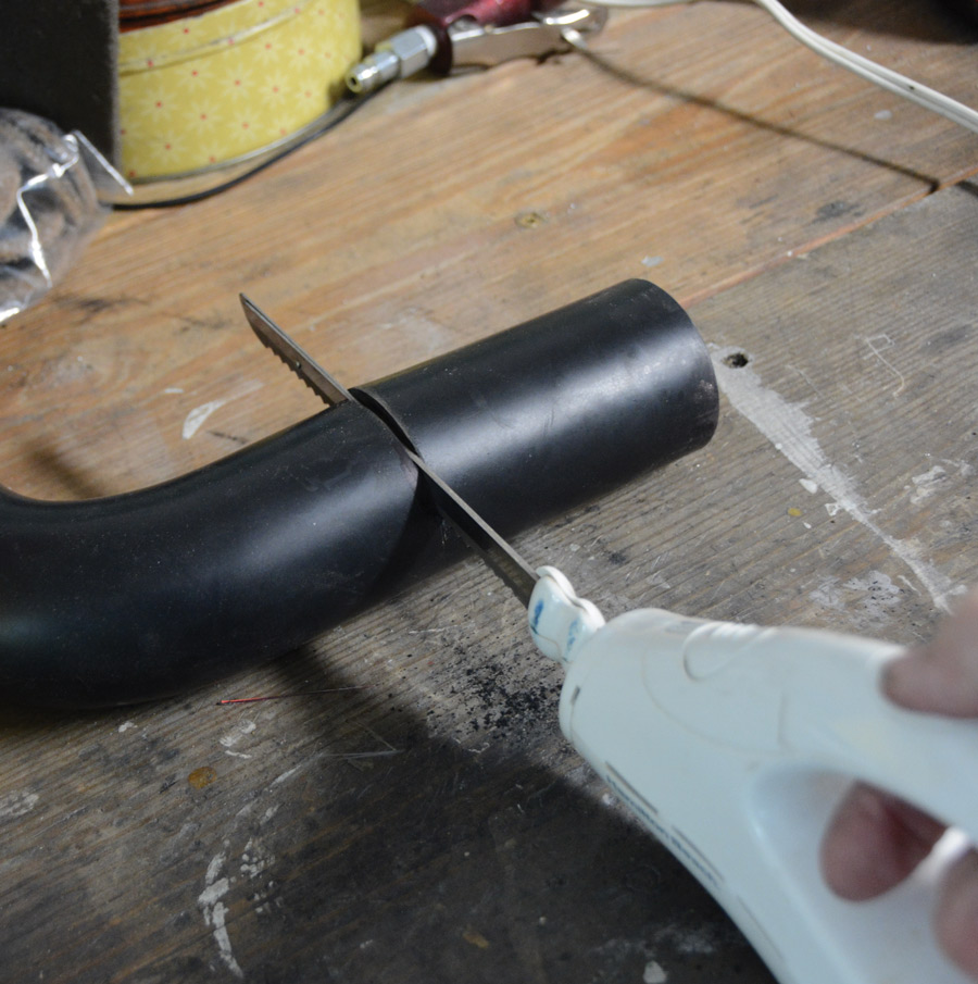
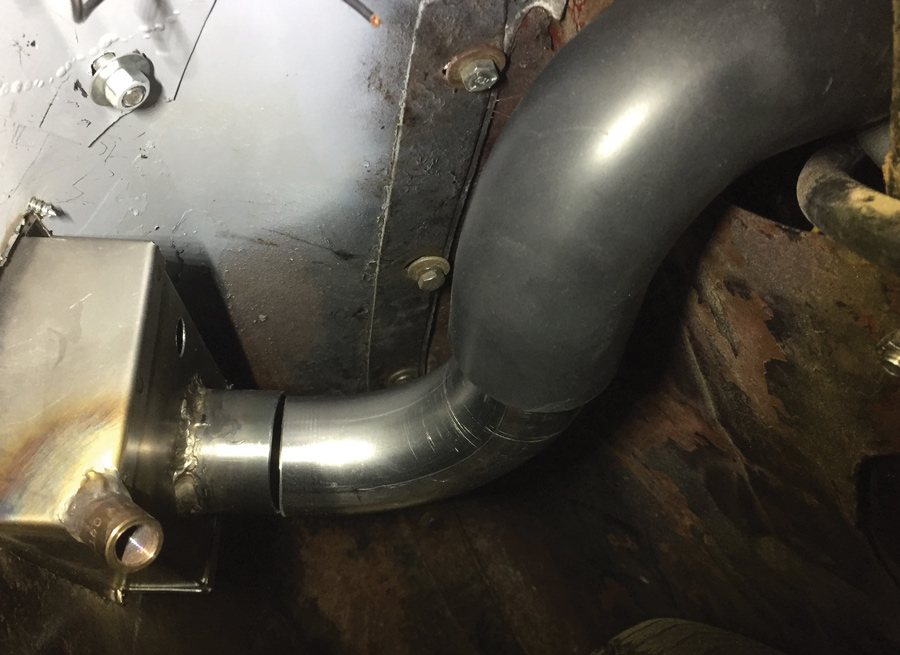
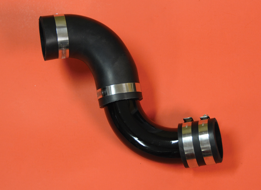
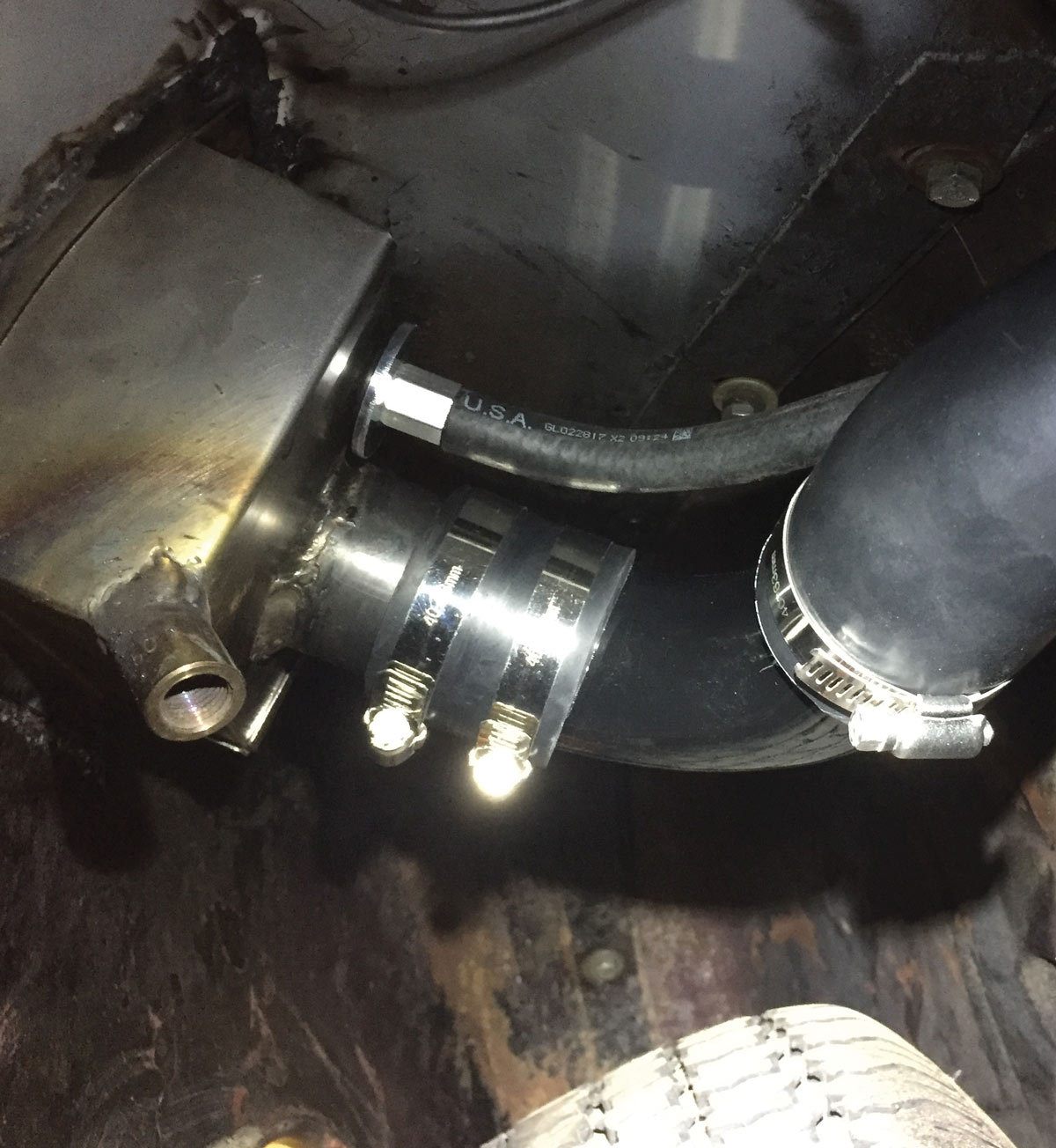
In an abundance of caution, we did not fit the face of the fill door flush with the fender just yet. Rather, we held the fill box to the fender with sheetmetal screws and set about forming the fill pipe connection from fill box to fuel tank. By doing it this way we could have still moved the fuel fill box forward and back and up and down should a minor adjustment be helpful. We routed the fill pipe using one piece of 90-degree, 2-inch steel tubing and one 2-inch, 90-degree rubber fuel hose. A short piece of 2-inch hose was used at the fill neck in the fender and the rubber 90 clamped to the gas tank. By using rubber hose at each end, we were able to make the final connection. Satisfied with the location we traced the outline of the fill box with a Sharpie and cut the hole (just inside the line) using a die grinder and cut-off disc.

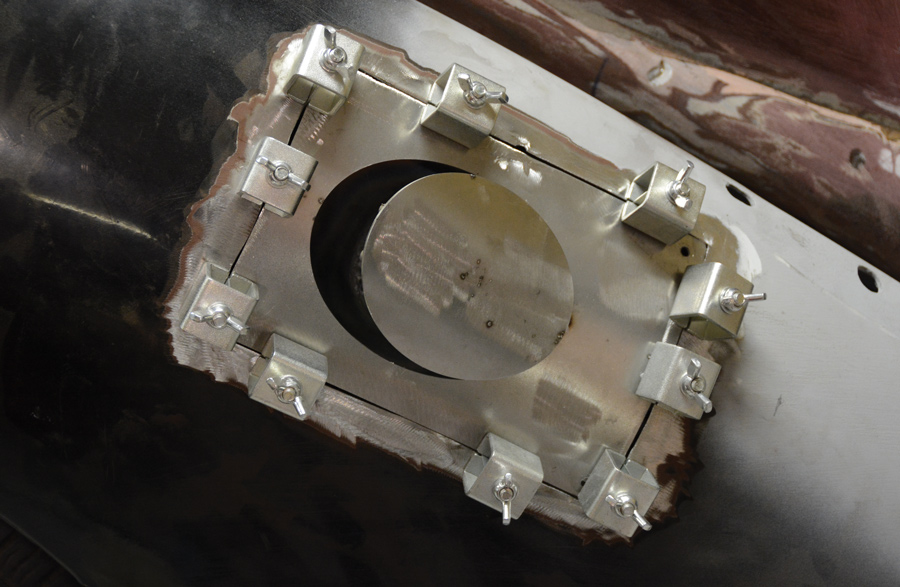
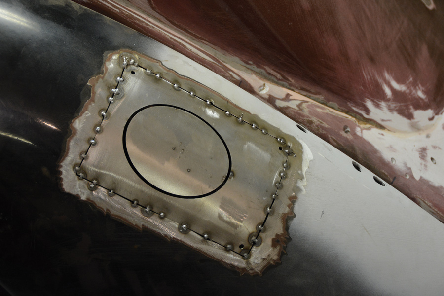
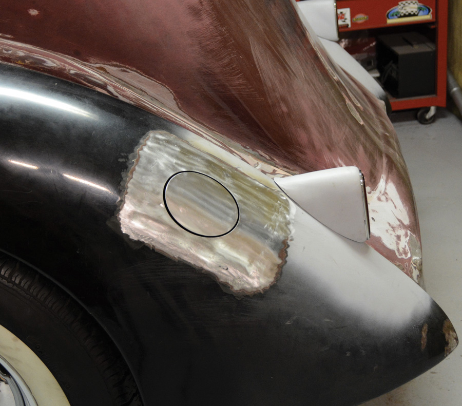
A little careful grinding and filing and we had a perfect opening for the gas door. We were pleasantly surprised to see to the 7-inch radius on the fill door was nearly a perfect match to our fender. We used nine Harbor Freight butt welding clamps to hold the fuel box to the fender. The clamps pulled the two panels together perfectly. Tack welding between the clamps held the two panels together and then we simply welded between the tacks, alternating from side to side top to bottom to prevent warping. With the welding complete we dressed the welds with a grinder. In the end we had a perfect fit with metalwork that would require a very minimal skim coat to finish the bodywork.

With careful work we finished the gas filler door installation, completing the modifications to the rear of the car. And just think, it all started with eliminating the spare tire.

Packard lights and a cool gas-fill door
1. Here is the look we were going for: Packard lights and a cool gas-fill door, but we are getting a bit ahead of ourselves.
simple template was used to find the sweet spot
2. The first step was finding the right location for the fill door. It must be higher than the tank to prevent splash-back and also must look “at home” in the fender. A simple template was used to find the sweet spot.
two fuel fill boxes
3. There are different radii faces for the fuel fill boxes. One is 7 inches (left) while the other is a nearly flat 32 inches. Speedway Motors carries the full line of round, square, and oval doors with either angle or straight-back fill boxes.
template to determine which radius would be best for our 1936 fender
4. Before ordering we printed this template out from the Speedway website and used it to determine which radius would be best for our 1936 fender. As luck would have it, the 7-inch is a near perfect match.
drilling a 1/8-inch hole in the center of our homebrewed template
5. After drilling a 1/8-inch hole in the center of our homebrewed template, we slipped a welding rod through the hole to see what would be required to connect from filler to fuel tank.
Two different angle fill boxes
6. Two different angle fill boxes are available, straight-back and angle-back. By using the welding rod through our 1/8-inch filler location hole we determined the straight-back would be best for our application.
front of the gas-fill door
7. From the front of the gas-fill door you can see the magnetic latch and the gas cap fitting. Remove the latch before welding as the magnets are in a plastic housing. Also remember to decide if you want the door to open left or right.
 gas-fill tube from the back
8. The gas-fill tube and associated gas cap come separate from the fill box. This worked out well for us as we had to shorten this piece of tubing to route the rest of the fill tubing.
one 7-inch radius, oval filler door assembly with cool fill-through cap
9. So, after a bit of planning and ordering from Speedway Motors, here is what we had to install in our 1936 Ford fender: one 7-inch radius, oval filler door assembly with cool fill-through cap.
2-inch hole saw in the fender
10. Once again using our original 1/8-inch hole as a pilot we began with a 2-inch hole saw in the fender. We opted to do the installation in steps to facilitate any unforeseen minor adjustments to the location.
Fuel pipe hole
11. We checked our fill pipe routing with the fill tube inserted in the fender to be certain we could make the connection from fill box to fuel tank. It was here we decided to shorten the fill tube a bit since the fill box also extends into the fender.
simple template of the size of just the fill box, not the body panel
12. We made a simple template of the size of just the fill box, not the body panel, for the initial location of the fill box.
template is taped to the fender and ever-so-slight location adjustments are made by simply rotating the template around the hole
13. That template is taped to the fender and ever-so-slight location adjustments are made by simply rotating the template around the hole. Certain the location was correct, we marked around the template with a Sharpie.
die grinder and thin cut-off wheel made quick work of opening up the hole
14. A die grinder and thin cut-off wheel made quick work of opening up the hole. A bit of work with a hand file will eliminate sharp edges.
marked the location panel with a Sharpie
15. Now the fill door assembly can be inserted in the fender. We used sheetmetal screws to hold it in place while we work on the fill pipe routing to the gas tank. Also we marked the location panel with a Sharpie.
marked the proper orientation on the fill box prior to welding
16. OK, call us crazy, but we wanted the gas cap script to be on line with the fender so it was readable. This does absolutely nothing to improve performance, but it makes us smile when we gas up. We marked the proper orientation on the fill box prior to welding.
lowest corner of the fill box was cut off and a 1/4-inch pipe coupling was welded in place
17. The lowest corner of the fill box was cut off and a 1/4-inch pipe coupling was welded in place. This serves as a drain for the fill box. We plan on threading in a 45-degree fitting to direct draining water down.
completed fill box
18. Here is the completed fill box. A shortened fill tube is welded in place. Using a step drill from Harbor Freight, we drilled a hole for the gas tank vent and show it installed. We opted for a righthand opening door.
carefully cut the opening inside our scribed lines and clamped the gas fill door into the fenders
19. We carefully cut the opening inside our scribed lines and clamped the gas fill door into the fenders with butt welding clamps also found at Harbor Freight. The clamps do a great job of fitting two panels.
tack welded (MIG) between each clamp, alternating sides to account for zero panel warping
20. We tack welded (MIG) between each clamp, alternating sides to account for zero panel warping. We then welded between the tack welds (TIG), again alternating sides for heat control.
dressed the welds down
21. We dressed the welds down, first with a 50-grit disc followed by 80-grit and a Scotch pad. We were very pleased with the fit of the piece and the appearance of the oval gas-fill door.
assortment of rubber tubes
22. Now it was time to make the connection from tank to fill tube. There is an assortment of rubber tubes available, be certain the rubber is certified fuel fill hose, other rubbers will decompose. We also used 2-inch steel 90-degree bend.
used an old electric kitchen knife to slice through the hose
23. Since our fuel line contains no steel reinforcing, we used an old electric kitchen knife to slice through the hose. Caution, this has been known to leave an odd taste in next year’s turkey.
fill tube
24. Now you can see why we shortened the fill tube prior to welding it in the box. Two fairly short 90-degree bends will make the connection.
finished hose/steel tubing connection ready for final installation
25.This is the finished hose/steel tubing connection ready for final installation. We took the time to paint the steel bend and four high-quality hose clamps complete the connections.
finished installation looking up into the fender behind the rear wheel
26. Here we see the finished installation looking up into the fender behind the rear wheel. Don’t forget to allow clearance for the rear tire to move up and down when considering the location. The vent hose is connected and our drain is aimed in a good direction. Bonus-style points awarded for aligned hose clamps.
aligned the fill tube in the box so the script on the “fill-through” gas cap was readable
27. We aligned the fill tube in the box so the script on the “fill-through” gas cap was readable. We also opted for a righthand door hinge and you can see the gas tank vent tucked up in the top right corner.
fuel filter between the new tank and our two new Stromberg carburetors
28. Since we had an all-new fuel system, we felt a fuel filter between the new tank and our two new Stromberg carburetors sure made good sense.
perfectly clean and safe fuel from the fill door to the Flat motor
29. We are now one step closer to the road with perfectly clean and safe fuel from the fill door to the Flat motor.
 SOURCES
Classic Instruments
(844) 342-8437
classicinstruments.com
Harbor Freight
harborfreight.com
Speedway Motors
(800) 979-0122
speedwaymotors.com
Modern Rodding
VOLUME 2 • ISSUE 10 • 2021