
Modern Rodding Tech
InTheGarageMedia.com
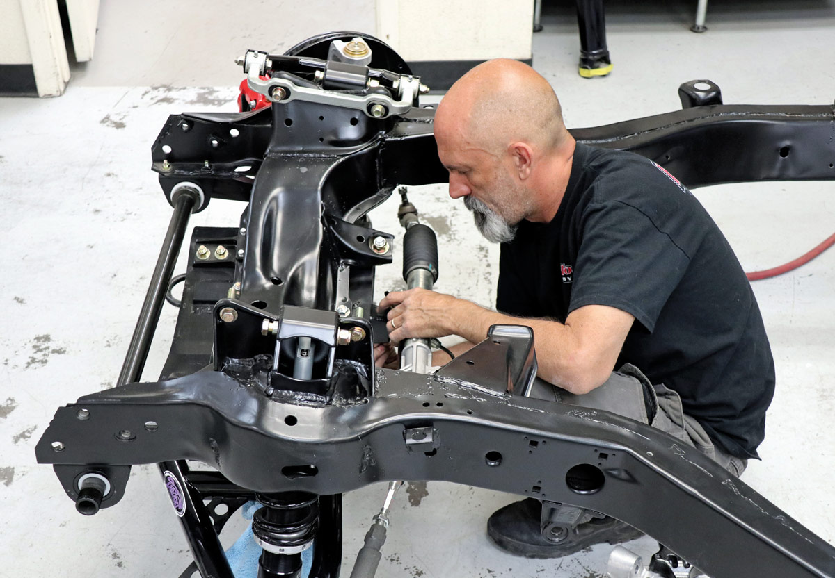
A technician installs a new steering rack into a black powder-coated Corvette frame, carefully aligning mechanical hardware within a clean, professional shop environment.
1. Geof Jones of Hot Rods By Dean (HRBD) handled all the Detroit Speed (DSE) suspension setup for the 1971 Corvette, which includes the SpeedRay IFS and the DECAlink IRS.
Modern Moves
Detroit Speed’s SpeedRay Front Suspension Modernizes our C3 Corvette Driving Experience
By Barry Kluczyk Photography by Brian Brennan
L

et’s be honest, vintage Corvettes look much better than they drive. The C2 (1963-67) and C3 (1968-82) generations marked a huge improvement in handling, thanks to their independent rear suspensions, but they certainly weren’t perfect.

The transverse leaf springs in the rear suspension had their limits, and although the front suspensions were fine in their day, they’re now as outdated as the Yellow Pages and TV repair shops—with performance and comfort levels to match. Upgrades for the front and rear suspensions have been around for decades, but more recently Detroit Speed (DSE) has introduced coilover conversion systems.

They include the SpeedRay front suspension kit and the DECAlink rear suspension setup. Both replace the original systems’ springs and shocks with coilovers as well as other enhancements, including rack-and-pinion steering for the front suspension. We’re adding both systems to our 1971 Corvette project, which will be powered by a big-torque 383 stroker small-block featuring FiTech fuel injection and a crank-trigger ignition with individual coils. The powertrain will also feature a TREMEC TKX five-speed transmission.

All the heavy lifting on the project is being handled by Phoenix-based Hot Rods By Dean (HRBD). They’re familiar with these Corvettes, including coilover conversions. We’re starting with the SpeedRay front suspension in this story and will cover the DECAlink system in an upcoming issue.

Unlike DSE systems for other vehicles, which require an entire subframe replacement for cars with a unitized chassis, the SpeedRay kit adapts to the original full-frame chassis on C2/C3 Corvettes (the frames remain essentially unchanged across generations). It features a bolt-on lower cradle that acts as the mounting base for the lower control arms and steering components, while the new upper control arms attach to the stock upper control arm mounts. Additionally, it has a large, thick stabilizer bar with splined ends and aluminum links connecting to the control arms.

The kit’s included JRi coilovers require their own upper mounting points, so DSE provides custom pockets that must be integrated into the chassis. This involves cutting and welding, making it more than just a bolt-on, however, the work can be done without removing the body from the chassis. In our project, though, HRBD separated them because the entire car is getting a restomod makeover.

With the upcoming new rear suspension, our weathered C3 Stingray is heading toward a more modern driving experience—one that offers the car improved reflexes, control, and comfort to match its timeless style.

A comprehensive performance suspension kit, including black control arms, coilovers, and a silver steering rack, laid out neatly against a white background for inventory.
2. What do you get for your money with a DSE SpeedRay IFS system? Well, take a look at this photo as we go through the process of hooking up all these pieces to deliver modern handling and performance beneath our vintage fiberglass design.
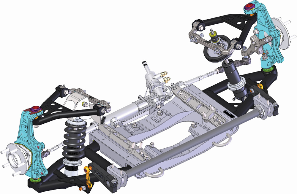
A detailed 3D digital rendering of the modern front suspension and subframe assembly, using color-coded parts to illustrate how the various mechanical components integrate.
3. This CAD drawing comes by way of DSE and shows in black the hard parts for the SpeedRay IFS. Next up would be the rack-and-pinion steering, spindle towers, and brakes.
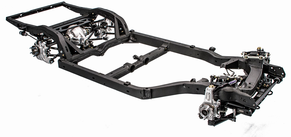
A fully assembled rolling chassis showing the refurbished black frame, modern front suspension, and a new silver rear differential with independent suspension.
4. Here is a direct front-on view of a C3 (1968-82) complete chassis with IFS and IRS. (There are changes in the various kits in the later years of the DSE kits.)
A high-angle shot showing the installation of silver aluminum spindles and black tubular control arms onto the refurbished, black-painted chassis subframe.
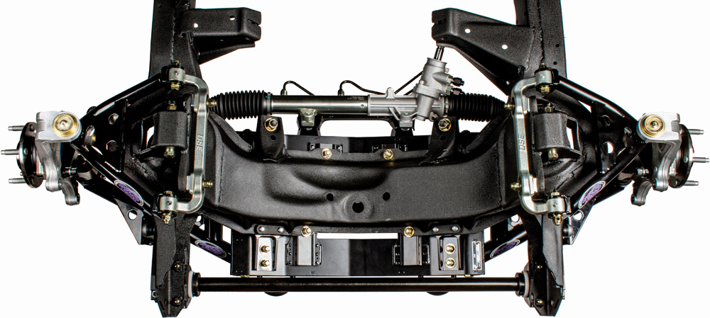
5. Here you can see the factory frame and front crossmember that is now equipped with a SpeedRay IFS.
An overhead view of the newly powder-coated black front subframe featuring a modern rack and pinion steering system and upgraded high-performance suspension geometry.
6. An overall view from the top/down shows off the DSE components along with the factory frame.
Close-up of the installed front suspension and brake assembly, featuring "Detroit Speed" branding and a BFGoodrich tire mounted on a modern silver alloy wheel.
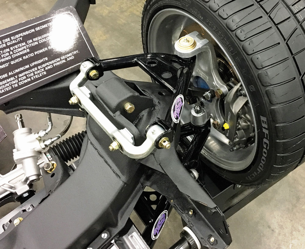
7. DSE’s SpeedRay front suspension system thoroughly upgrades the C2/C3 Corvette with coilover shocks, tubular control arms, rack-and-pinion steering, and more. The components attach to the stock chassis but some fabrication is needed for the upper coilover mounts.
The rear of a yellow C3 Corvette body shell sits in a shop, stripped of its lights and bumpers to reveal weathered fiberglass and exposed, rusted exhaust components.
8. Our 1971 Corvette project car was straight and solid when we found it, but it desperately needed cosmetic, powertrain, and driveline updates. It will undergo a complete transformation, which is why HRBD is starting by pulling the body off the chassis.
A bare, heavily rusted Chevrolet Corvette ladder frame sits elevated on jack stands in a garage, representing the starting point of the structural restoration.
9. Although it didn’t look perfect, the chassis was thankfully solid and free of rust. The C2/C3 frames are known for rusting inside the boxed sections and around the welded areas of the rear kickups.
A close-up view of a rusted front suspension mounting point on the old Corvette frame, with a large yellow arrow pointing to specific areas requiring repair.
10. The frame will be stripped and refinished but only after some initial suspension installation work is finished. This involves cutting out a section of each original shock mount (arrow) and welding new mounts for the SpeedRay suspension’s upper control arms and coilovers.
A worker wearing protective gloves uses a power grinder to cut into the rusted Corvette frame, creating bright orange sparks as they prep the metal for new components.
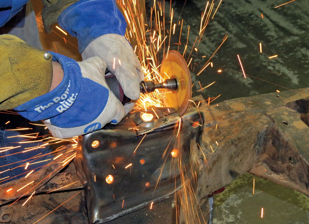
11. DSE’s instructions provide measurements for where to cut the shock mounts. After marking guidelines on the mounts, the upper sections are cut out of the steel.
A close-up of the rusted chassis after a section has been cut away, showing the raw metal edges and the interior cavity of the frame rail prepared for reinforcement.
12. After the shock mounts are removed, the original spring perches must also be cut and modified to accommodate the new mounts.
A new, unpainted steel suspension bracket is test-fitted onto the original rusted Corvette frame, showing the contrast between the old chassis and new performance parts.
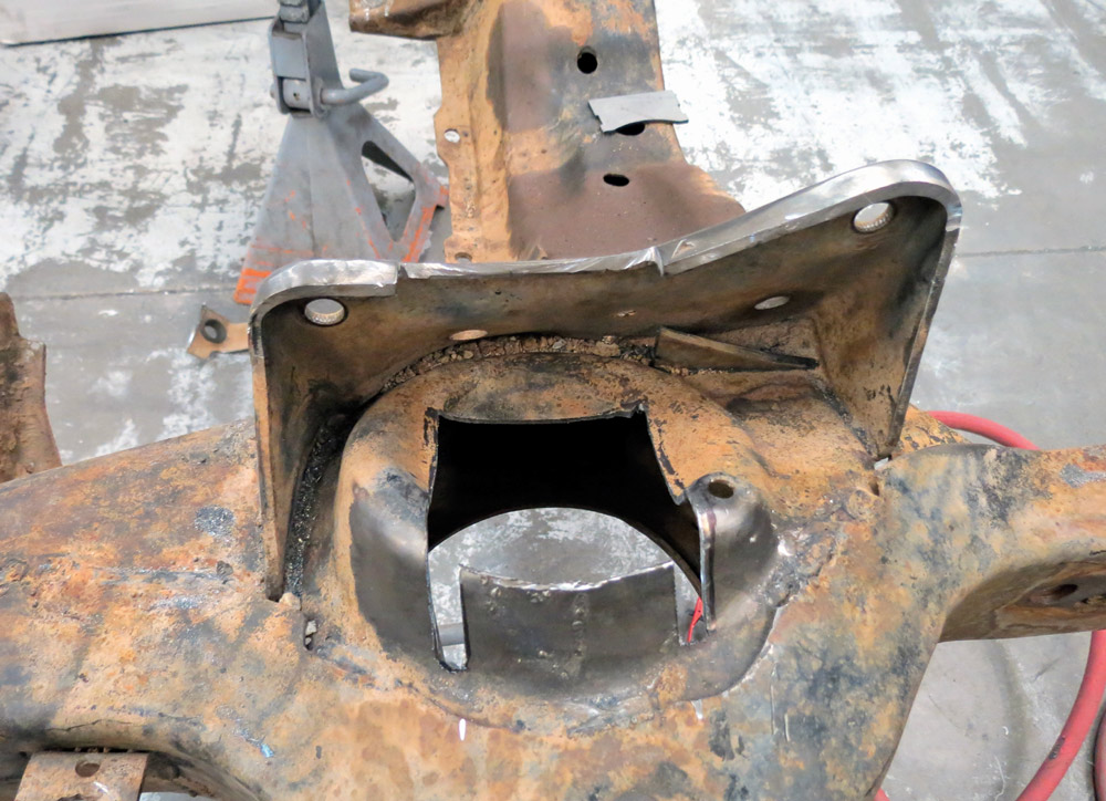
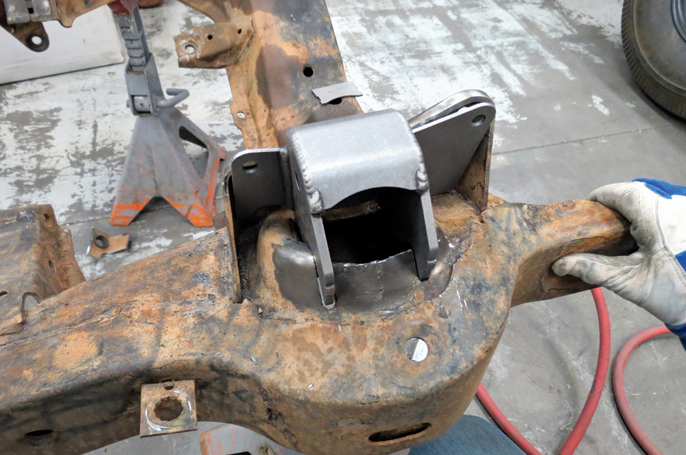
13. The new mounts are included with the SpeedRay kit, and one is shown here in a test-fit before final installation. In addition to providing the top mount for the corresponding coilover assemblies, the mounts also support the upper control arms.
A technician wearing a welding helmet and protective gear uses a MIG welder to permanently attach new steel brackets to the original Corvette frame in a shower of blue light.
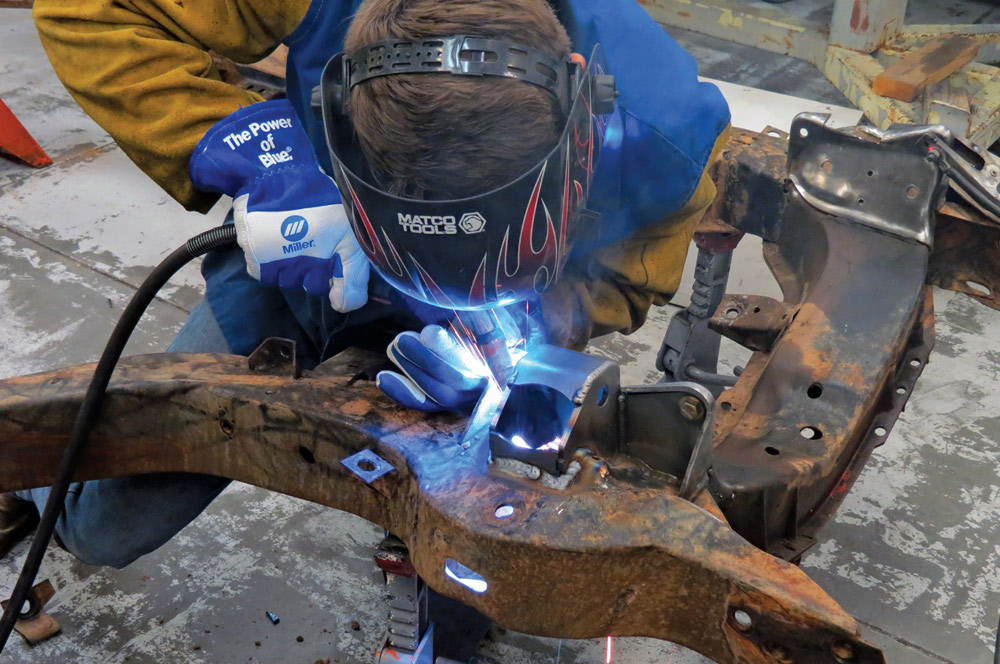
14. With the fitment and necessary measurements double-checked, the new mounts are welded to the chassis.
Close-up view of a freshly completed weld inside a frame pocket, showing the beads of metal joining a new steel sleeve to the interior of the Corvette's chassis rail.
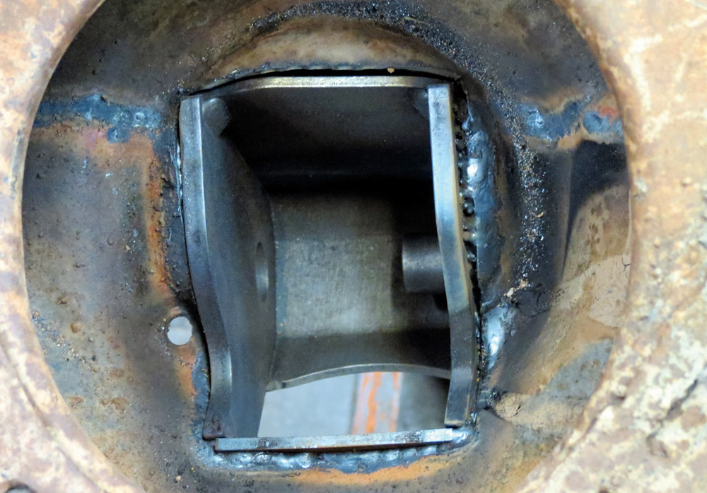
15. Attachment also includes welding the inside of the new mounts to the bottom of the spring perches. This concludes the welding and fabrication portions of the project.
A top-down view showing a black alignment tool bolted across the rusted frame rail next to a newly welded-in suspension pocket to ensure perfect structural geometry.
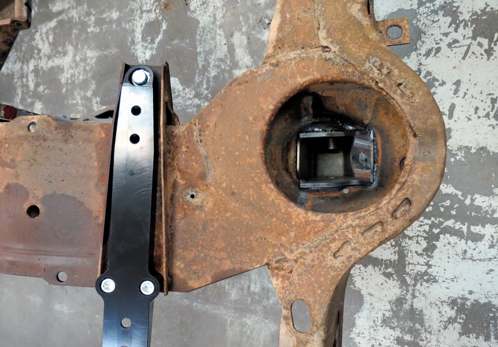
16. Next, the new system’s cradle adapter plates are installed within the factory lower control arm brackets—but not before ensuring the brackets are straight and flat.
A wide-angle perspective of the complete, black powder-coated rolling chassis, showing the fully integrated modern front and rear suspension systems on a white background.
17. An overall view of a fully prepped powdercoated stock frame with the DSE IFS and IRS in place.
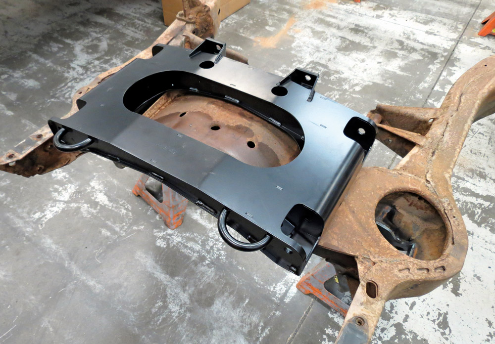
A newly painted black steel crossmember is placed onto the rusted chassis for a final mock-up, illustrating the structural upgrades being added to the vintage frame.
18. Next is the new front cradle, which simply attaches to the adapter plates. Additional mounting holes might need to be drilled into later C3 frames, but that wasn’t necessary for this chassis.
Close-up of a black "Detroit Speed" tubular control arm and adjustable coilover shock absorber installed on the refurbished frame, supported by a blue cloth on a jack stand.
19. The lower control arms mount on the new cradle—and yes, the frame has been refinished between the time the cradle was installed and the rest of the suspension was bolted into place. One of the coilover assemblies is also shown here. The spring rate is 650 lb/in, and the damper is a double-adjustable unit from JRi.
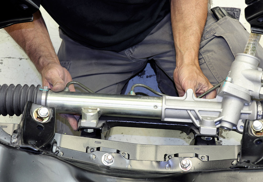
Close-up of a technician's hands positioning a polished silver steering rack onto the black powder-coated chassis, securing the unit with heavy-duty mounting hardware.
20. Before moving onto the upper control arms, the kit’s rack-and-pinion steering system is installed next. Before bolting it onto the new cradle, the rack was centered and the tie-rod ends installed. The system has a 13:1 ratio and requires just two turns, lock to lock.
A wide view of the refurbished black chassis from above, showing the installed silver steering rack and the intricate welds and bolts securing the new suspension subframe.
A macro view of a black powder-coated universal joint for the steering assembly, featuring blue paint markings on the caps and a secured hex bolt with a nut.
21-22. Here’s a tip: The steering rack needs a specific 36-spline U-joint, which has a 17mm diameter on the rack side and a standard 3/4-inch DD size on the other end. It’s not included with the kit and must be ordered separately under PN 092525DS.
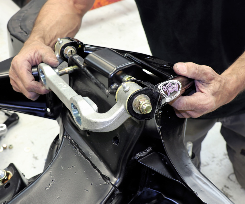
Close-up of a technician's hands installing a black "Detroit Speed" upper control arm onto the chassis, highlighting the silver pivot shaft and gold-colored hardware.
23. Next up are the upper control arms. The assemblies bolt into the original upper control arm positions. Double-check that the correct arm is on the correct side of the chassis.
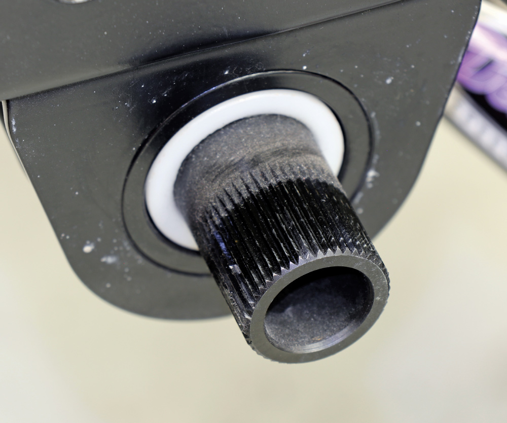
Extreme close-up of a splined black sway bar end emerging through a white low-friction bushing inside the black powder-coated chassis mounting bracket.
24. After the upper control arms comes the stabilizer bar. Supplied brackets mount to the chassis and the bar is supported by high-tech composite bushings.
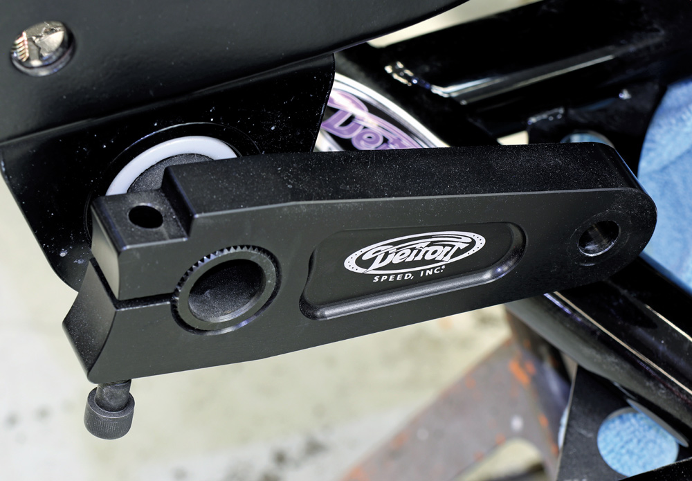
Detail shot of a black "Detroit Speed" suspension arm clamped onto the splined end of a sway bar, showing the precision fit and the high-quality logo on the component.
25. Connecting bars and endlinks attach the stabilizer bar to the suspension. The bars should be mounted in the same position and on the same stabilizer splines on both the left and right sides of the suspension.
Close-up of the front suspension assembly showing the black coilover spring, an adjustable tie rod end, and a black tubular control arm resting on a jack stand.
26. The endlinks are bolted to the connecting bars and then to the lower control arms.
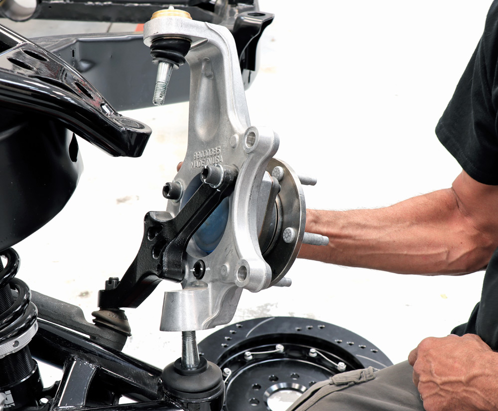
A technician aligns a large, cast aluminum front spindle onto the ball joints of the new control arms, showing the "MADE IN USA" casting and integrated wheel hub.
27. Next, install the spindle assemblies. They attach to the upper control arms first, then are lowered onto the lower ball joints. A specific torque procedure for these mountings is included in the instructions. DSE also recommends applying high-strength Red Loctite 262 to the threads of the lower ball joint.
Detailed view of a heavy-duty outer tie rod end connected to the steering arm with a castle nut and cotter pin, illustrating the robust steering components.
28. After that, the outer tie rods are connected to the spindles’ steering arms.
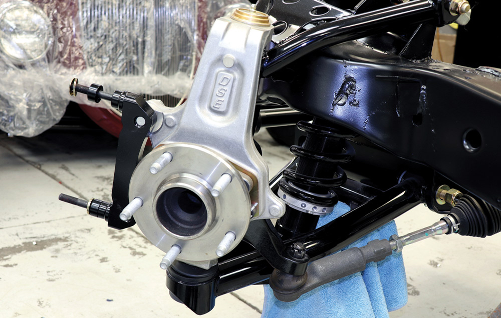
Front suspension detail showing the installed aluminum spindle, wheel hub with studs, and the mounting bracket for a high-performance disc brake system.
29. With that, the suspension installation is essentially complete. DSE’s instructions provide details on setting and adjusting the ride height, but this is done later, after the vehicle is reassembled. In the meantime, the basics for a set of Wilwood brakes will be installed, and, as this image shows, the caliper bracket is already in place.
A technician's hands carefully slide a large, black slotted and drilled Wilwood brake rotor onto the wheel hub studs of the newly assembled front suspension.
30. Large, 14-inch-diameter drilled-and-slotted two-piece rotors are then installed on the spindle hubs.
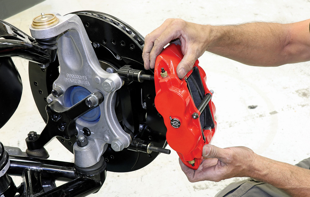
A technician's hands carefully slide a bright red, six-piston Wilwood brake caliper onto the mounting studs of a newly assembled front suspension with a black slotted rotor.
31. The loaded, six-piston calipers are slipped over the rotors and snugged to the caliper brackets. There’s plenty more to do with the brake system, including routing all-new lines, but again that comes later.
A detailed close-up showing the finished high-performance brake setup, featuring a large black Wilwood rotor and a red multi-piston caliper mounted to the refurbished chassis.
32. The SpeedRay front suspension and Wilwood brake upgrades thoroughly modernize our classic C3 project car. We’re looking forward to checking out its reflexes in the near future, but we’ve still got the rear suspension and brakes to contend with—and we’re going to detail them in an upcoming issue.

Modern Rodding
VOLUME 7 • ISSUE 64 • 2026