Modern Rodding TECH

InTheGarageMedia.com

green Brookville ’29 Ford roadster
Timeless Tradition
Speedway Motors Answers The Call
By Ron Ceridono Photography by Jason Scudellari
O

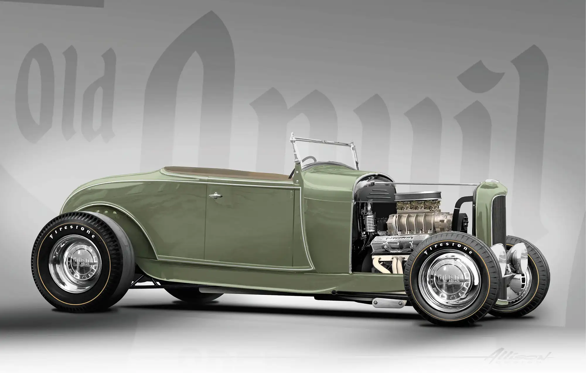
ver the years Jason Scudellari has built several muscle cars and classic trucks and he often displays his talents in Modern Rodding technical stories. But despite his lengthy involvement in most things hot rod, he’s never built a traditional roadster of his own—until now.

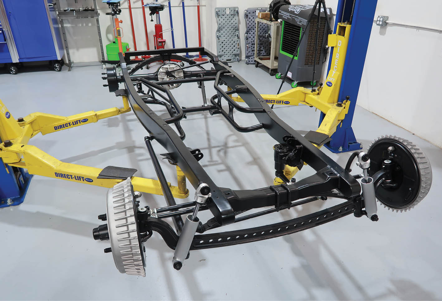
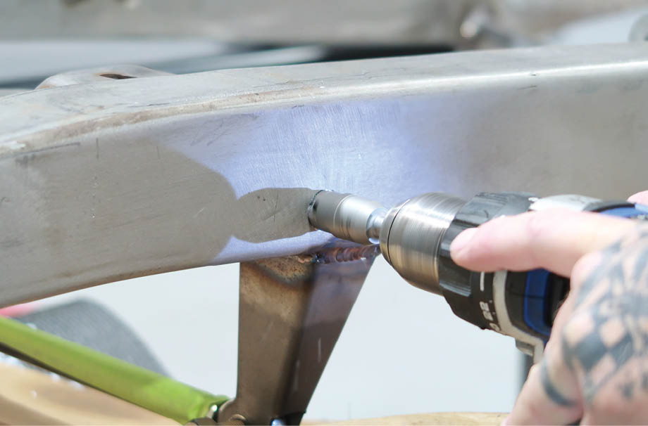
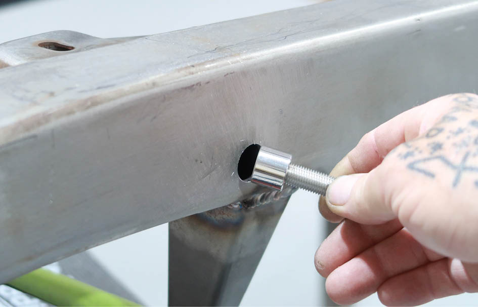
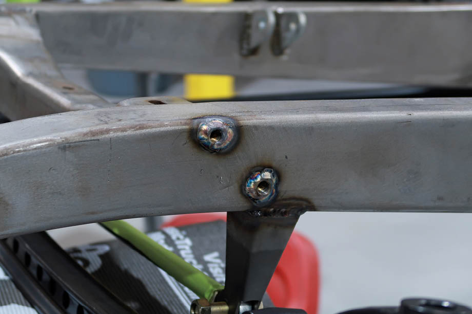
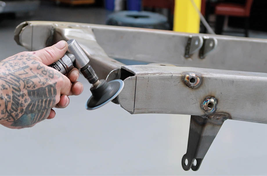
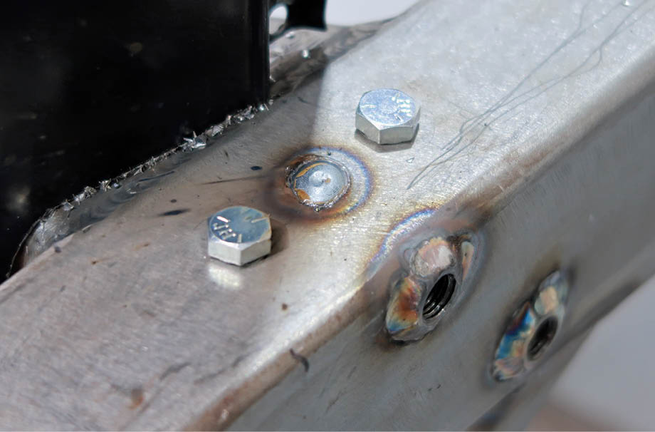
When it comes to hot rods, few are more traditional than what is often described as an A/V-8, a Model A Ford body on a ’32 Ford frame—in this case the body is from Brookville and the frame is from Speedway Motors (PN 91657007). This amalgamation does require some tweaking to make the two come together, in this case the necessary modifications to the shape of the framerails were made by Old Anvil Speed Shop. In addition, they reinforced the framerails with Speedway’s boxing plates (PN 9108969) and weld-in tubular crossmember kit (PN 91657029). All of this was documented by Ryan Manson in the Sept. ’23 issue of Modern Rodding.

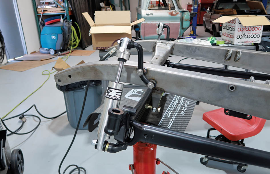
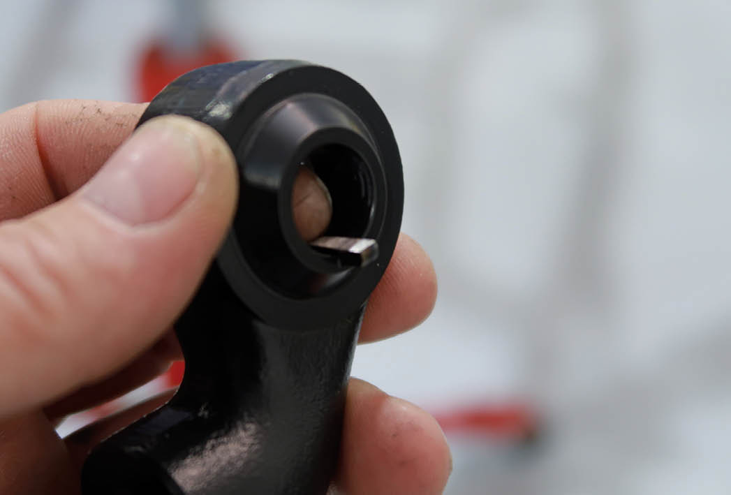
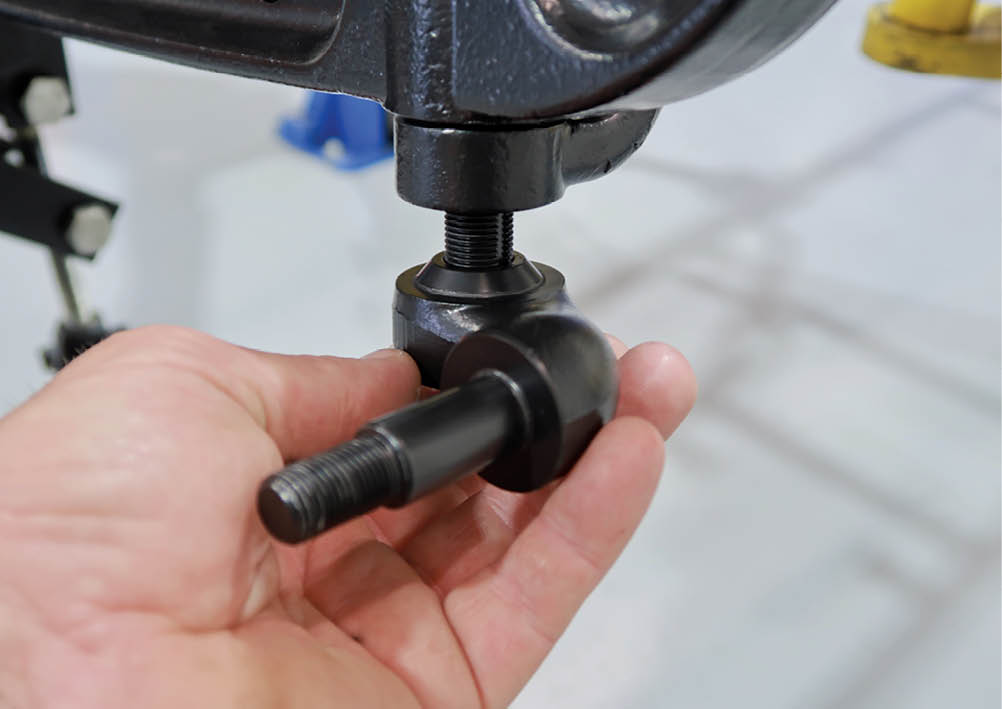
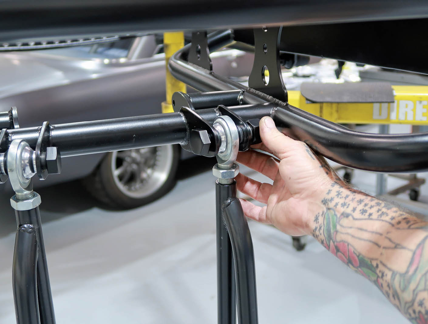
With the necessary changes to the frame wrapped up, Scudellari turned his attention to the suspension. Up front is a laundry list of traditional suspension components from Speedway, including a dropped I-beam axle, reversed eye spring, and ’48-52 Ford F-1–style shock brackets. Holding the axle in place is a pair of Speedway (PN 91645127) split wishbones made from 12-gauge steel with forged ends—in the rear are 11/16-18 threaded bungs (Ford tie-rod end size). The bolt-on steering arms are Speedway 3-3/4-inch drop (PN 7022756), for use with split radius rods. Also available are 1-3/4 inch dropped arms for hairpins and four-bars (PN 7022754).

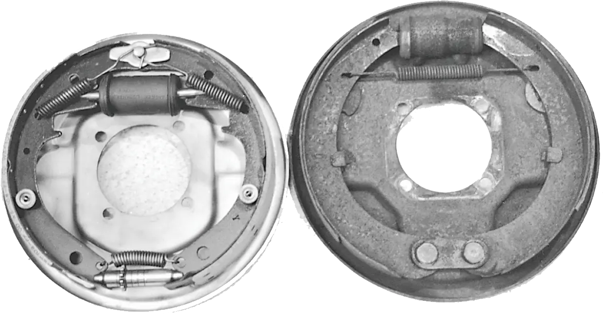
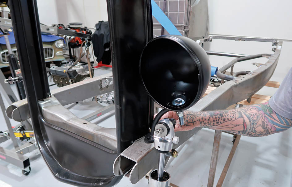
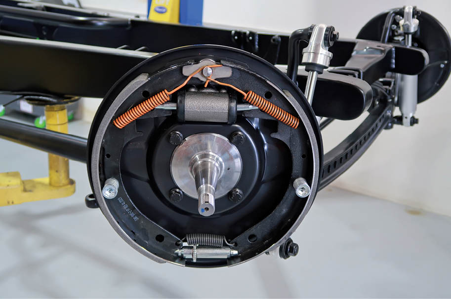
Another tradition that Scudellari chose to stick with was the use of drum brakes rather than modern discs. The fact is not all drum brakes were created equal, so the decision was made to use the more effective Lincoln self-energizing style that was once a common swap for early Ford brakes. Not surprisingly, original Lincoln brakes are hard to find, but all is not lost as reproductions are offered by Speedway. Several variations of these brake upgrades are offered that can be used with ’37-41 or ’42-48 Ford spindles (’37-41 spindles have a round flange; the ’42-48 spindle have a square backing plate mounting flange and use longer kingpins). When using original spindles up some material may need to be removed on the top of the spindle. However, to make things easy Speedway now offers new, modified, ’37- to ’41–style spindles that are ready-to-use (PN 910-3211). Self-energizing rear brake kits are also available for ’37-48 Ford cars and ’37-47 Ford pickups with original rear axles.

There are two basic options when choosing Speedway’s Lincoln-style brakes: they can be had with 12×1.75 or 12×2 shoes. Reproduction 12-inch stock-style drums with 5-on-5.5 bolt circle are available in 1.75- and 2-inch widths—also available are new 2-inch-wide Buick aluminum brake drums. In this case Scudellari opted for the complete brake kit (PN 91604052) that included Buick drums, backing plates, hubs, spindles, kingpins, bearings, and seals.

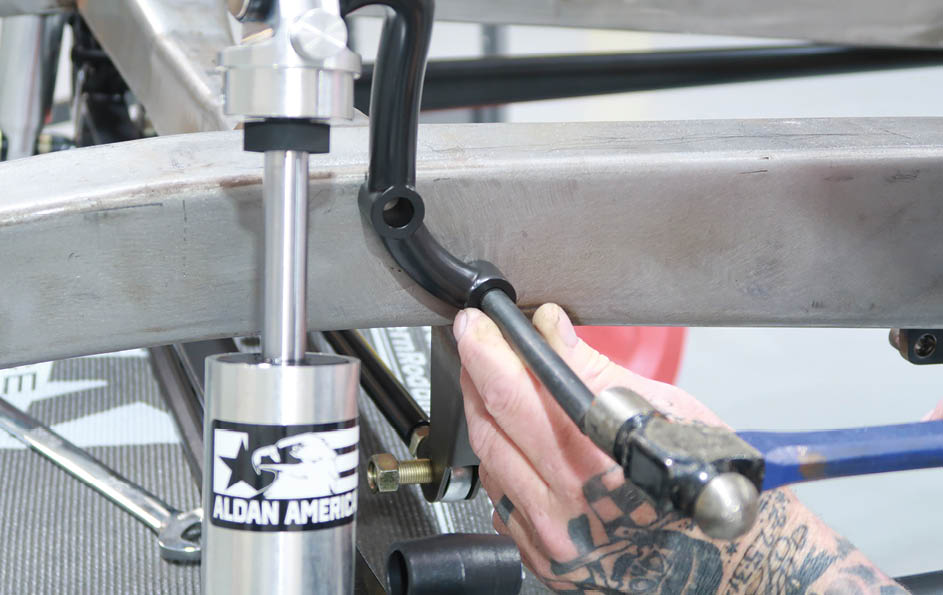
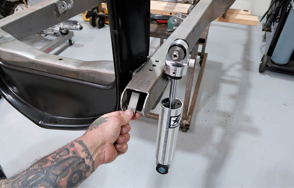
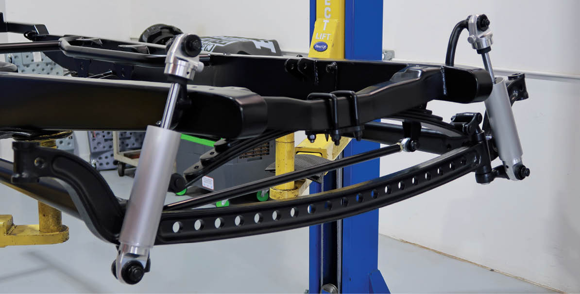
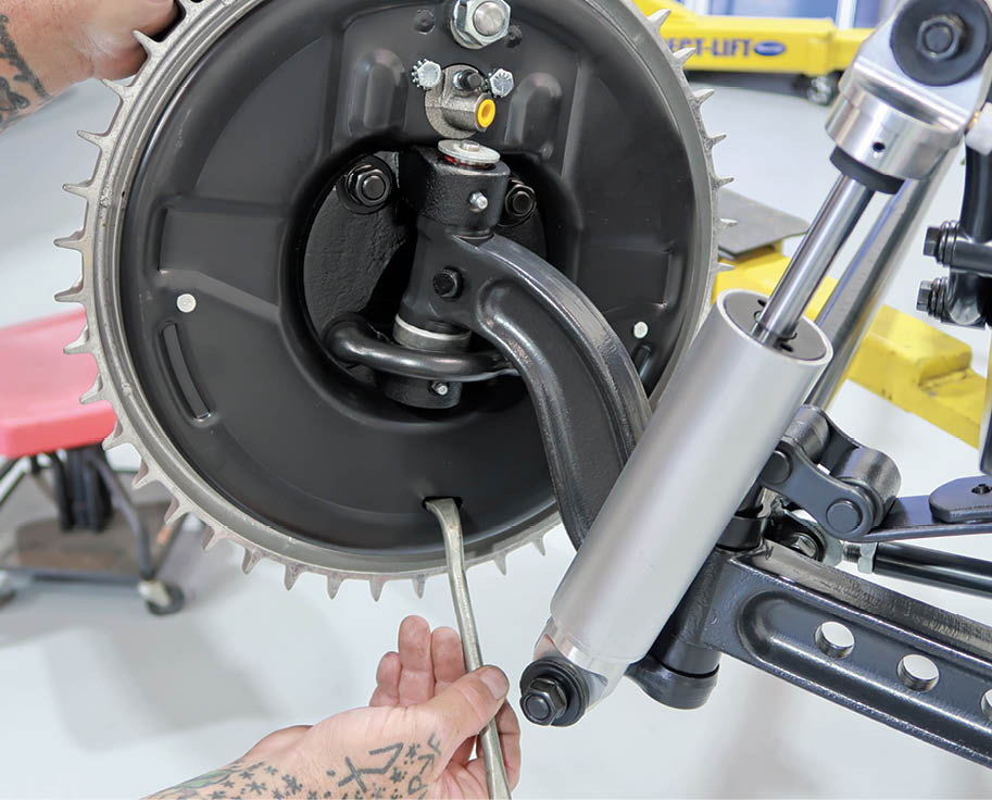
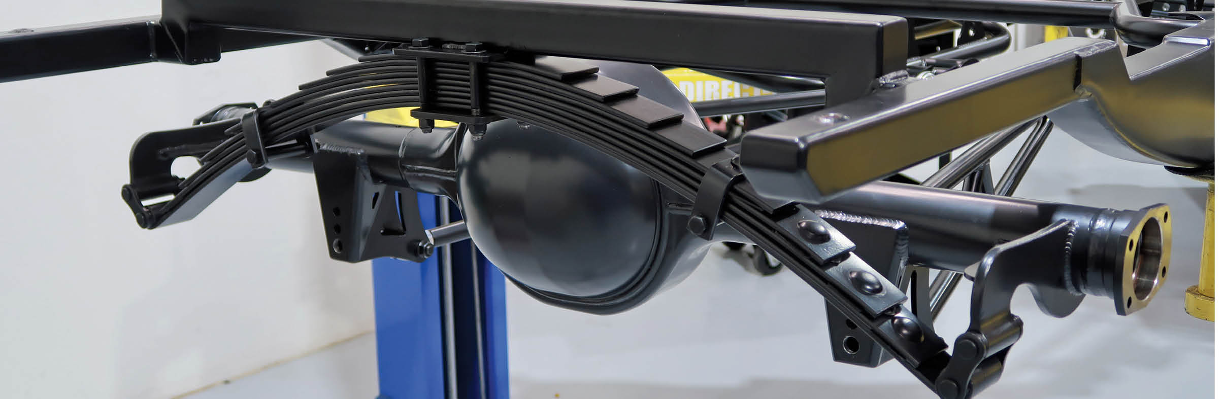
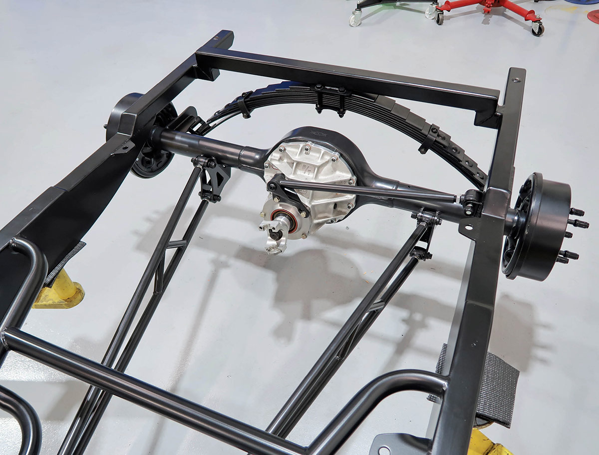
In the rear a John’s Industries rearend assembly is combined with Speedway’s universal ladder bars, Panhard bar, transverse spring, and Aldan shocks. Rear stopping power is supplied by 10-inch-diameter drum brakes.

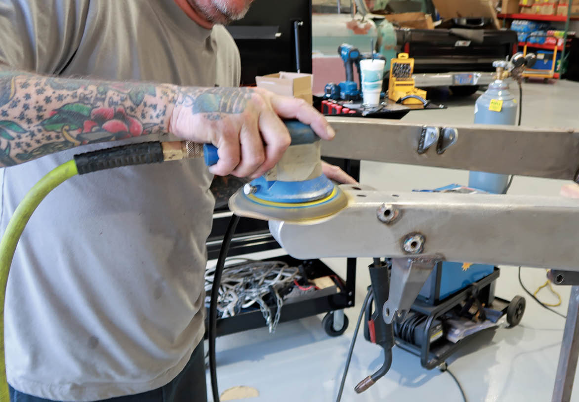
The final step in completing the chassis was to have Kings Powder Coating apply the super-smooth semigloss black finish to the framerails. All the suspension components were covered with Cerakote by Cerakote SoCal. This black, thin film ceramic finish provides corrosion abrasion resistance with a unique look. ARP fasteners were used throughout.

Scudellari has proved two things with the construction of his A/V-8: traditional hot rods are still alive and well and they can be built with all new parts. Tradition really is timeless.

The Self-Energizing Solution
After stubbornly refusing to install hydraulic brakes on his automobiles for years, Henry Ford relented and used Lockheed-designed brakes on Fords and Mercurys from 1939-48. With this style of hydraulic brake each of the shoes were anchored to the backing plate at the bottom; the front shoe used a longer lining than the rear and a stepped wheel cylinder with the larger diameter facing forward. Basically, the brake shoes worked independently of each other.

Bendix brakes were used on a variety of vehicles, oddly enough Ford chose them from 1939-on for Lincolns, Fords and Mercurys had them from 1949-on. Bendix brakes differ from the Lockheed design in that they are self-energizing, which basically means the brake shoes work together. When Bendix brakes are applied the shorter front shoe contacts the revolving drum and tries to rotate it. That movement is transferred through the adjuster to the longer rear shoe, pushing it into the drum with increased force. Simply put, Bendix brakes generate far more stopping power than the Lockheed design with equivalent hydraulic pressure.

2 different types of brakes
On the left is a typical Bendix brake from a ’53-56 F-100; 11 inches in diameter, they were a common swap for early Ford brakes (the front, shorter shoe is to the left). Note the bottoms of the shoes are held together with a spring and adjuster. On the right is a 12-inch Ford Lockheed brake. Note the long shoe is forward, the stepped wheel cylinder and that both shoes are anchored to the backing plate.
Jason Scudellari’s ’29 Ford highboy will ride on a traditional Speedway ’32 Ford frame (PN 91657007) modified by  Old Anvil Speed Shop to accept the Brookville Model A body.
1. Jason Scudellari’s ’29 Ford highboy will ride on a traditional Speedway ’32 Ford frame (PN 91657007) modified by Old Anvil Speed Shop to accept the Brookville Model A body.
One concession to contemporary suspension technology is a pair of Aldan double-adjustable front shocks (PN AS-451). They will attach to the frame with reproduction F-1 shock brackets.
2. One concession to contemporary suspension technology is a pair of Aldan double-adjustable front shocks (PN AS-451). They will attach to the frame with reproduction F-1 shock brackets.
After marking the locations of the shock bracket’s mounting bolts with a transfer punch, Scudellari cut holes in the framerails for mounting bungs.
3. After marking the locations of the shock bracket’s mounting bolts with a transfer punch, Scudellari cut holes in the framerails for mounting bungs.
Made from solid round stock, the bungs were threaded to accept the shock brackets’ mounting bolts.
4. Made from solid round stock, the bungs were threaded to accept the shock brackets’ mounting bolts.
Here the shock mounting bungs have been welded in place. Mounted to the bottom of the frame is the bracket for the Speedway Motors Panhard bar.
5. Here the shock mounting bungs have been welded in place. Mounted to the bottom of the frame is the bracket for the Speedway Motors Panhard bar.
Speedway’s F-1 shock brackets are available in two lengths: 5-1/2 inches (PN 91036008) or 6-1/2 inches (PN 91036009). These are the stainless steel versions (PN 91036006).
6. Speedway’s F-1 shock brackets are available in two lengths: 5-1/2 inches (PN 91036008) or 6-1/2 inches (PN 91036009). These are the stainless steel versions (PN 91036006).
To clean up the front of the frame, Scudellari decided to “bob” the front framehorns. A hole saw happened to be the right size to mark the cuts to be made.
7. To clean up the front of the frame, Scudellari decided to “bob” the front framehorns. A hole saw happened to be the right size to mark the cuts to be made.
A cutoff wheel on an air grinder was used to shorten the framerails to a more appropriate old-school hot rod length.
8. A cutoff wheel on an air grinder was used to shorten the framerails to a more appropriate old-school hot rod length.
Out came the air grinder again, this time to round the bobbed ’rails with a 36-grit abrasive disc.
9. Out came the air grinder again, this time to round the bobbed ’rails with a 36-grit abrasive disc.
Prior to capping the ends of the shortened ’rails a pair of reinforcements for the headlight stands were put in place.
10. Prior to capping the ends of the shortened ’rails a pair of reinforcements for the headlight stands were put in place.
The reinforcement plates are held to the tops of the ’rails with rosette welds; the plates have threaded holes to accept the headlight brackets’ bolts.
11. The reinforcement plates are held to the tops of the ’rails with rosette welds; the plates have threaded holes to accept the headlight brackets’ bolts.
Speedway’s highboy stainless steel headlight mounts (PN 91061025) measure 4-3/4 inches from mounting surface to the top of headlight cup. Headlights are 7-inch Dietz-style buckets from Speedway (PN 91101008-1).
12. Speedway’s highboy stainless steel headlight mounts (PN 91061025) measure 4-3/4 inches from mounting surface to the top of headlight cup. Headlights are 7-inch Dietz-style buckets from Speedway (PN 91101008-1).
With the headlight bracket reinforcements in place the fronts of the bobbed 'rails were closed with 16-gauge flat stock.
13. With the headlight bracket reinforcements in place the fronts of the bobbed ‘rails were closed with 16-gauge flat stock.
After welding all the edges the capped framerails were ground and sanded smooth.
14. After welding all the edges the capped framerails were ground and sanded smooth.
Slots cut in Speedway’s stainless steel lower shock mounts (PN 91036102) accept a key that prevents them from rotating on the spring perch and misaligning the shocks.
15. Slots cut in Speedway’s stainless steel lower shock mounts (PN 91036102) accept a key that prevents them from rotating on the spring perch and misaligning the shocks.
The Speedway spring perches have a corresponding keyway to accept the lower shock mount.
16. The Speedway spring perches have a corresponding keyway to accept the lower shock mount.
To install the lower shock mounts extra-long spring perches are required (PN 91033047).
17. To install the lower shock mounts extra-long spring perches are required (PN 91033047).
The dropped-and-drilled Speedway axle is attached to a 1-3/4-inch-wide, 31-inch-long, reversed-eye Posies Super Glide spring. The Panhard bar will be level when the chassis is at ride height.
18. The dropped-and-drilled Speedway axle is attached to a 1-3/4-inch-wide, 31-inch-long, reversed-eye Posies Super Glide spring. The Panhard bar will be level when the chassis is at ride height.
Stopping power up front comes from Speedway Motor’s 12x2 Bendix brake conversion kit.
19. Stopping power up front comes from Speedway Motor’s 12×2 Bendix brake conversion kit.
Included in Speedway Motors’ brake kit are reproduction Buick aluminum brake drums with steel liners and 5-on-5.5 lug bolt pattern.
20. Included in Speedway Motors’ brake kit are reproduction Buick aluminum brake drums with steel liners and 5-on-5.5 lug bolt pattern.
Speedway Motors’ complete brake kit came with all the necessary parts, including reproduction ’37-41 Ford spindles modified to fit with the Lincoln backing plates.
21. Speedway Motors’ complete brake kit came with all the necessary parts, including reproduction ’37-41 Ford spindles modified to fit with the Lincoln backing plates.
The steering box is a reproduction Vega, Speedway PN 91032204. Tie rod and drag link kit (PN 91632501) comes with 5/8-inch rod ends.
22. The steering box is a reproduction Vega, Speedway PN 91032204. Tie rod and drag link kit (PN 91632501) comes with 5/8-inch rod ends.
In the rear is a Posies 2-1/2-inch dropped ’35-36 Ford-style spring with reversed eyes, Speedway PN 5803536.
23. In the rear is a Posies 2-1/2-inch dropped ’35-36 Ford-style spring with reversed eyes, Speedway PN 5803536.
Inside the Strange aluminum centersection from John’s Industries is a 3.70:1 gearset.
24. Inside the Strange aluminum centersection from John’s Industries is a 3.70:1 gearset.
A pair of Speedway 54-inch ladder bars (PN 91645169) along with a Panhard bar (PN 91649002) keep the rear axle housing located.
25. A pair of Speedway 54-inch ladder bars (PN 91645169) along with a Panhard bar (PN 91649002) keep the rear axle housing located.
The fronts of the ladder bars attach to the tubular center crossmember with spherical rod ends.
26. The fronts of the ladder bars attach to the tubular center crossmember with spherical rod ends.
To dampen the movement of the rear suspension Aldan double-adjustable shocks (PN AS-356) were installed.
27. To dampen the movement of the rear suspension Aldan double-adjustable shocks (PN AS-356) were installed.
In the Garade Media - Tech Center - Frontier shop supplies
SOURCES
Aldan American
(310) 384-7478
aldanamerican.com
ARP
(800) 826-3045
arp-bolts.com
Brookville Roadster
(937) 833-4605
brookvilleroadster.com
Cerakote SoCal
(562) 715-6973
cerakote-socal.com
John’s Industries
(800) 332-3450
johnsindustries.com
Kings Powder Coating
(714) 326-9336
kingspowdercoat.com
Old Anvil Speed Shop
(657) 223-9889
oldanvilspeedshop.com
Speedway Motors
(800) 979-0122
speedwaymotors.com
Modern Rodding
VOLUME 5 • ISSUE 41 • 2024