Modern Rodding TECH

InTheGarageMedia.com

Concept drawing of a gray and black ford roadster
’36 Ford Roadster
Part 2: Rad Rides By Troy Continues the Build
By Ron Covell Photography by Adam Banks
W

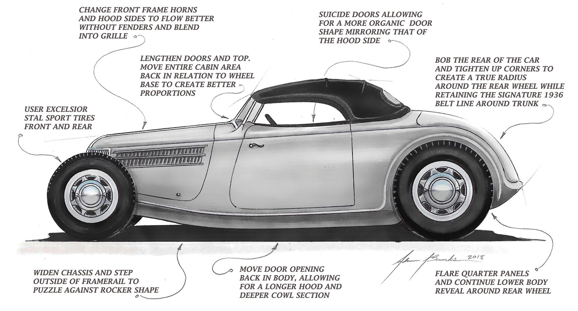
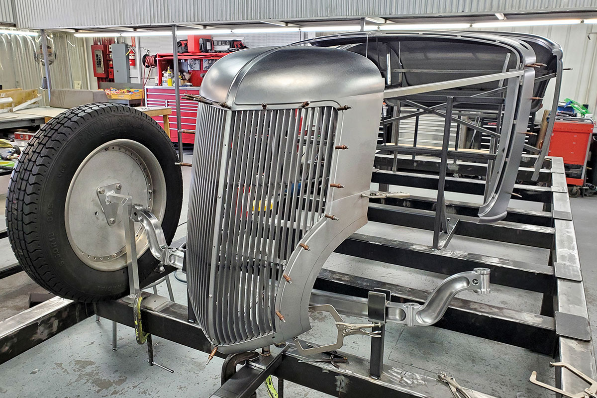
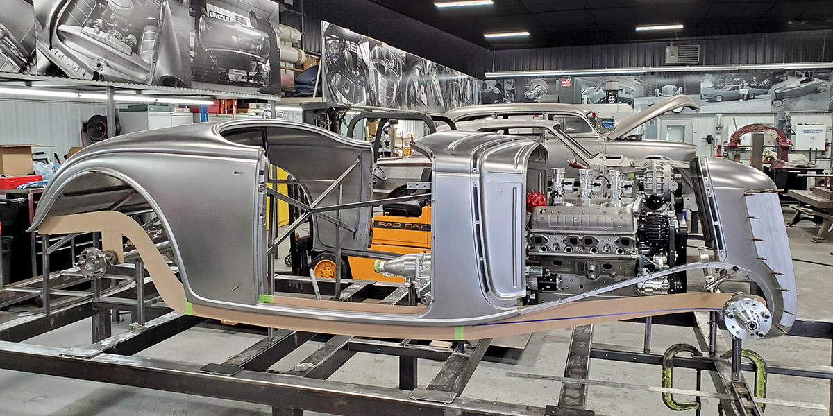
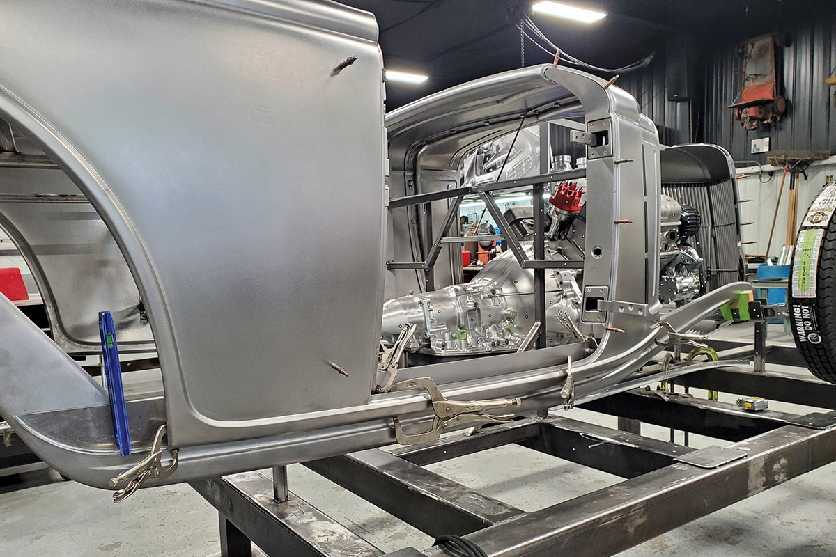
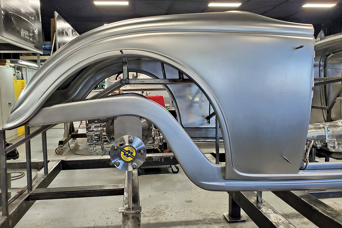
e previously looked at how the crew at Rad Rides by Troy, through the efforts of Adam Banks, scratch-built a body for Ross Myers’ ’36 fenderless roadster. While a new (or modified) body is most often fitted to an existing frame, they took a different approach here: waiting to design the frame until the shape of the body and grille shell were finalized. This allowed them to do an exceptional job of integrating the fit and contours of the two components.

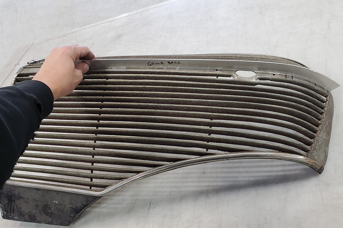
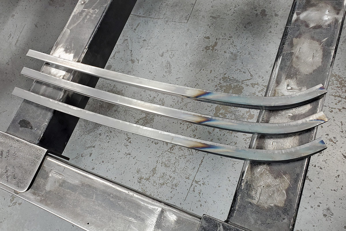
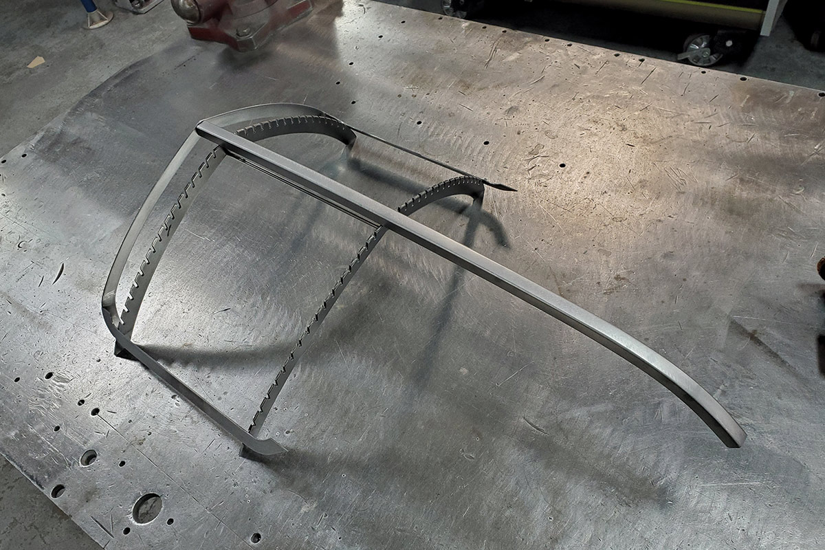
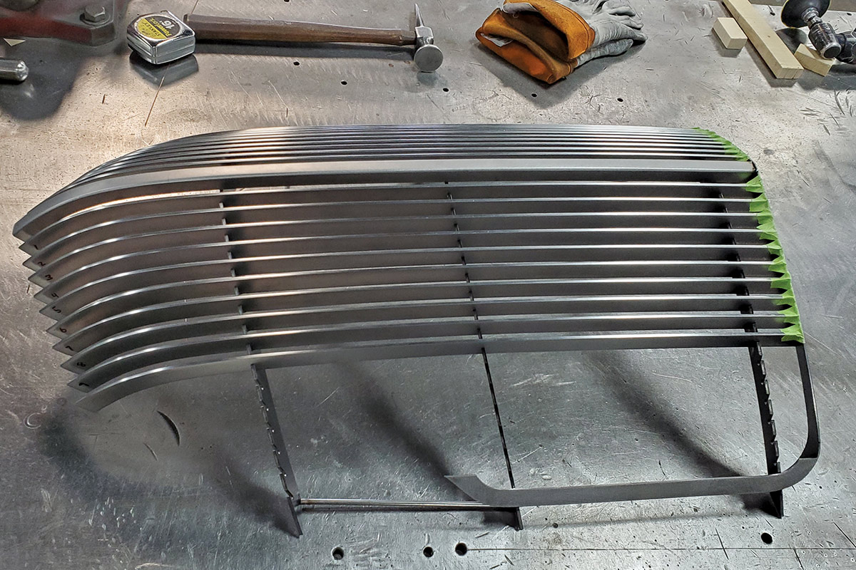
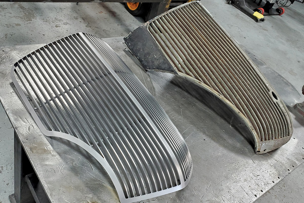
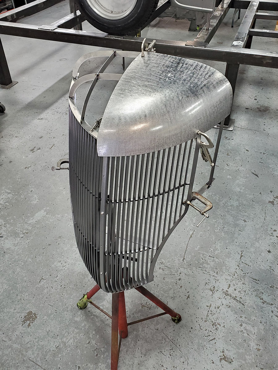
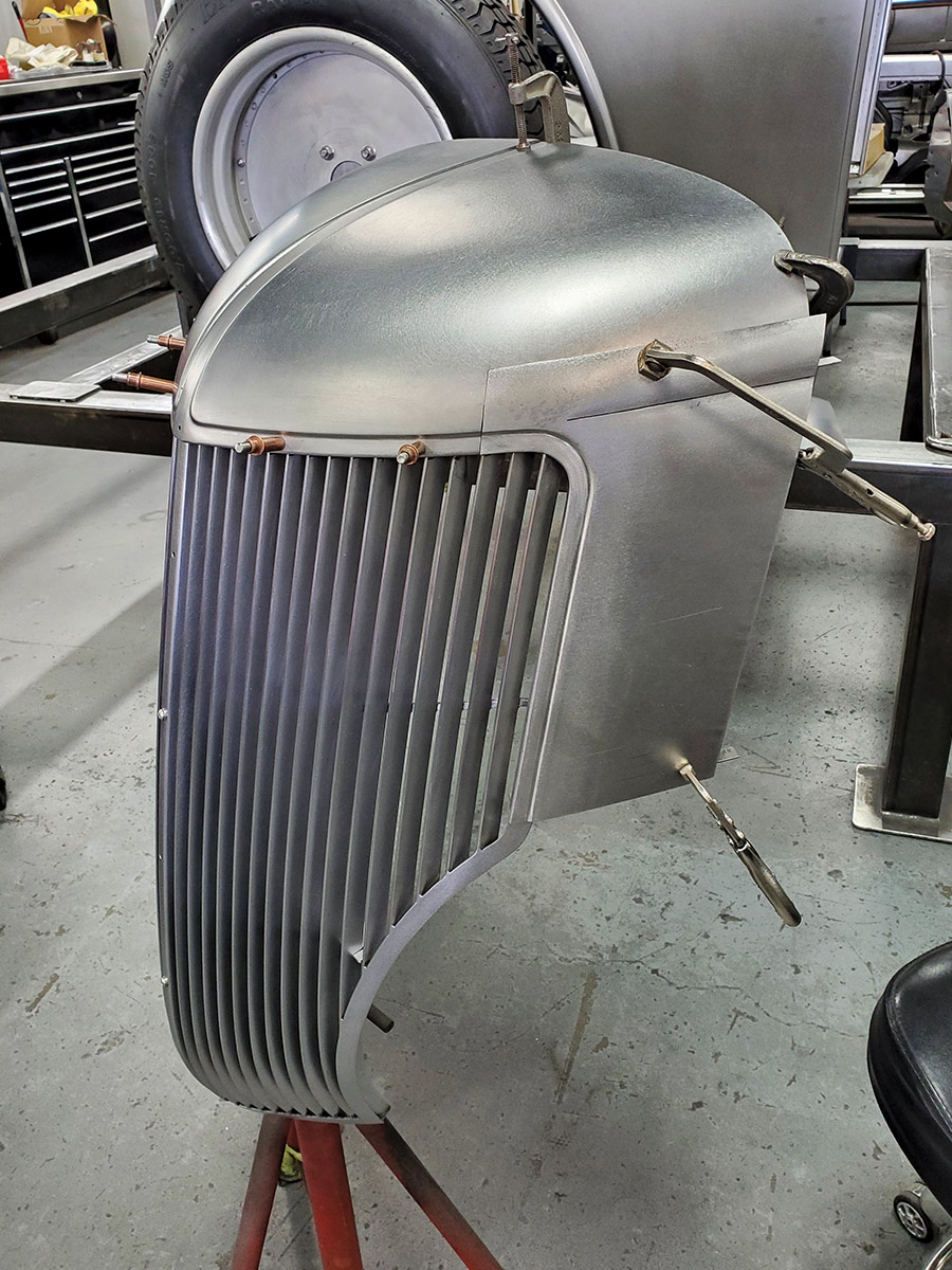
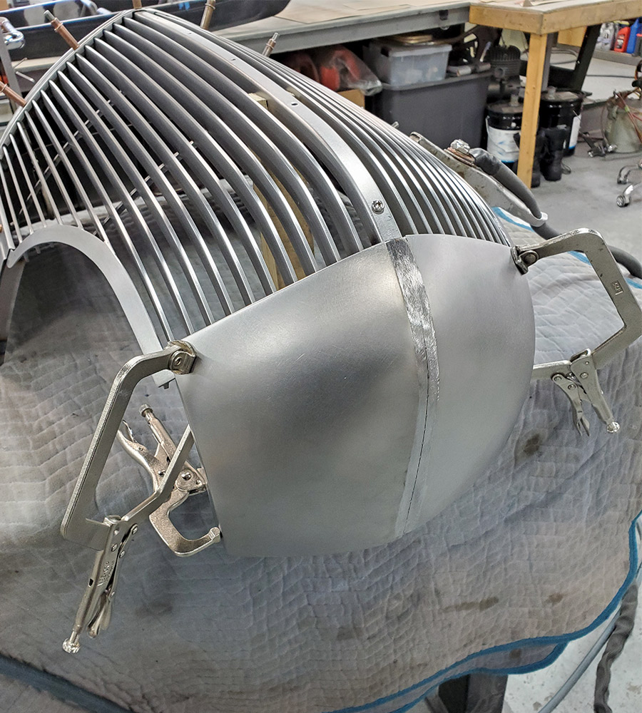
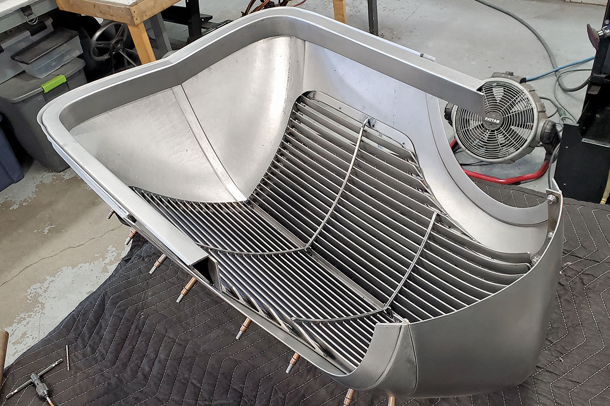
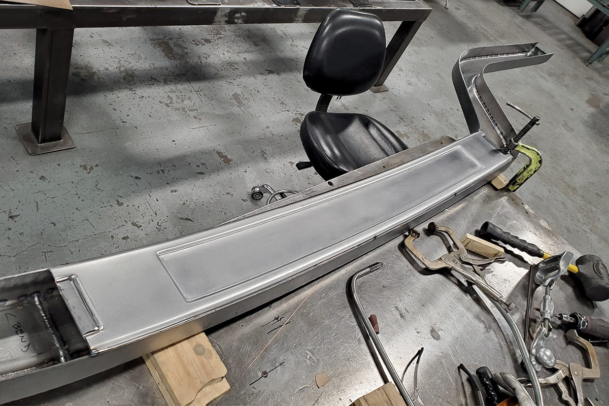
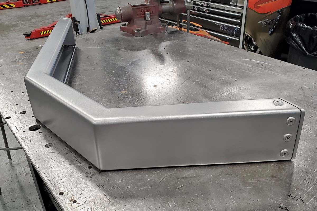
The grille itself was completely scratch-built from steel, and while it retains the “flavor” of a stock ’36 grille, it is sectioned 4-½ inches, and a complete shell has been built from 18-gauge steel to surround the grille. As you’ll see in the photos, this was a massive undertaking. The grille of a car really sets the essence of the build, so this was a component they had to get right.

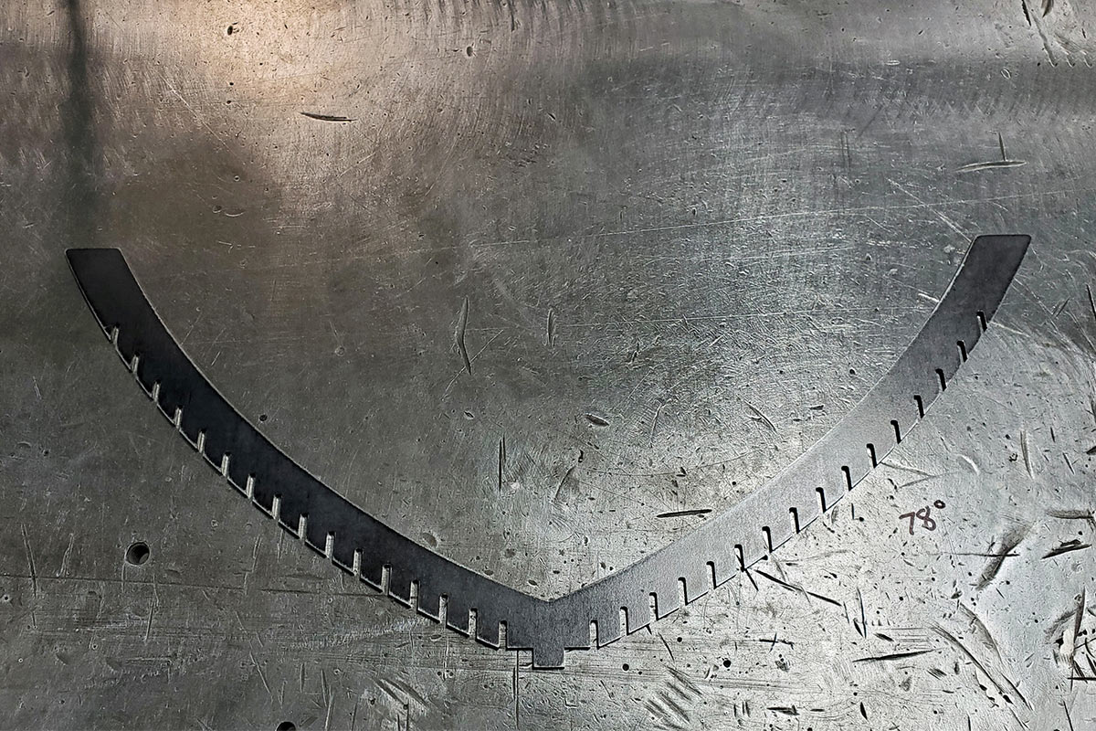
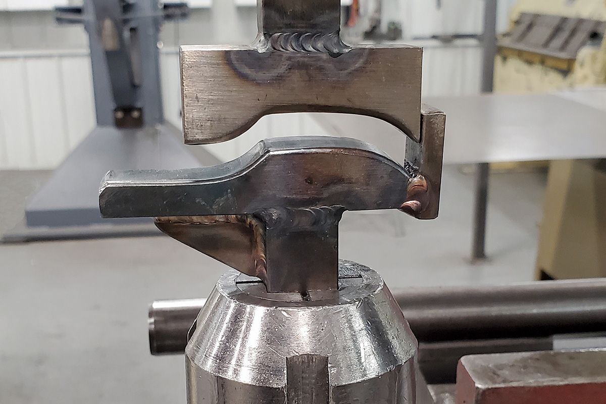
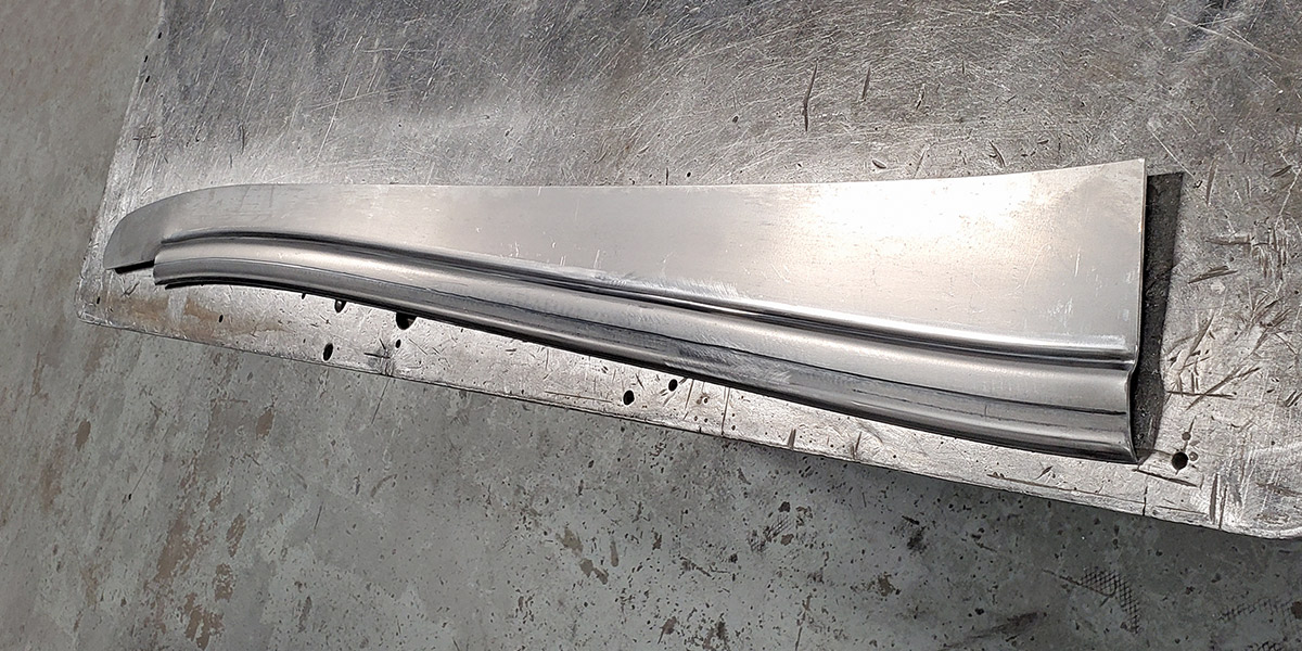
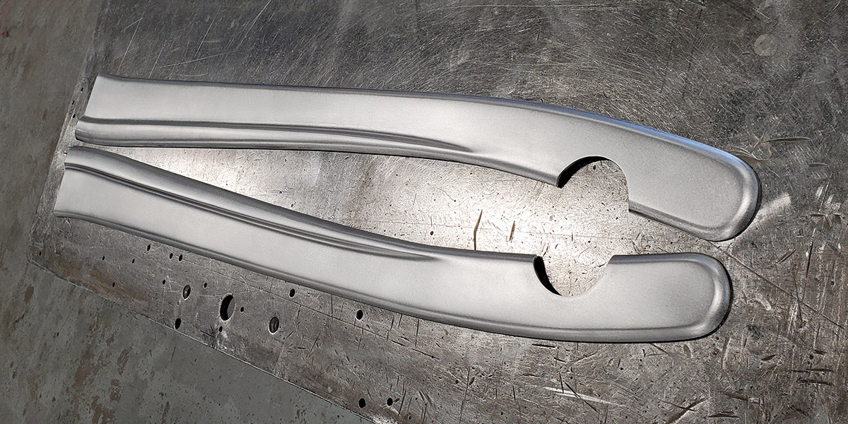
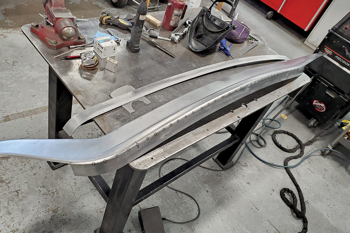
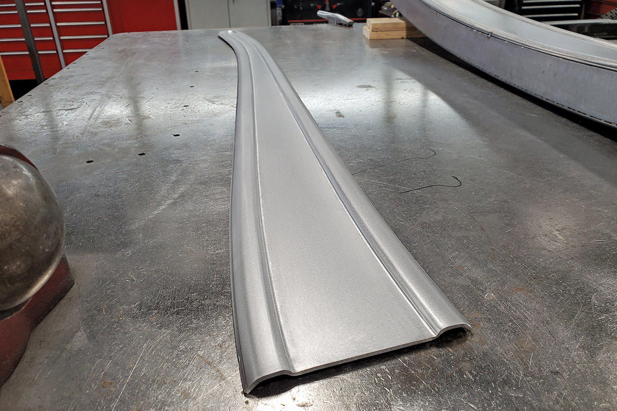
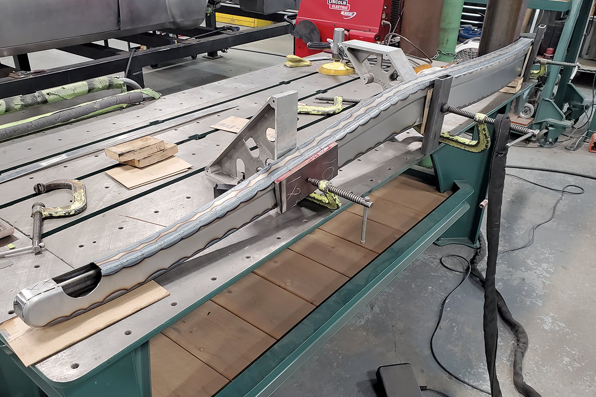
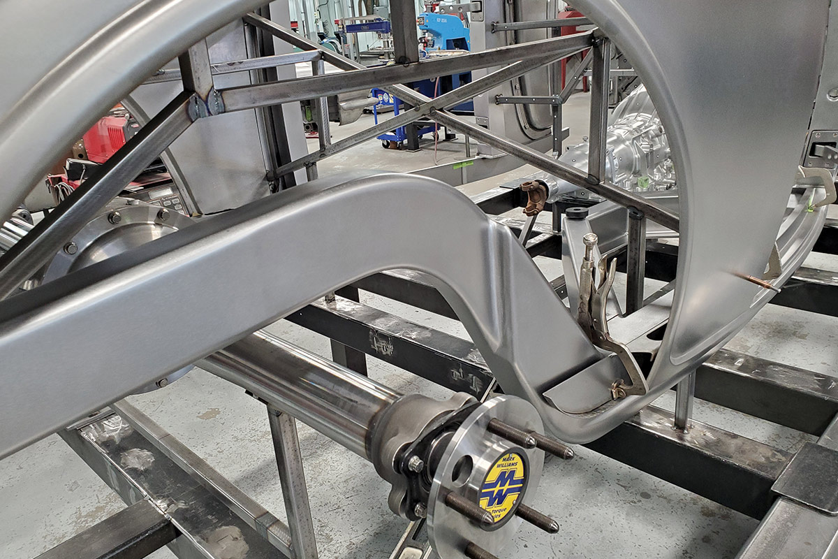
Since this will be a fenderless car and much of the frame will be visible, they decided to add a “rib” to the bottom of the framerails, somewhat like the detail on a ’32 Ford. Special dies were made for a Pullmax machine to shape this unique detail. This will become one of the many striking features of this cutting-edge project.

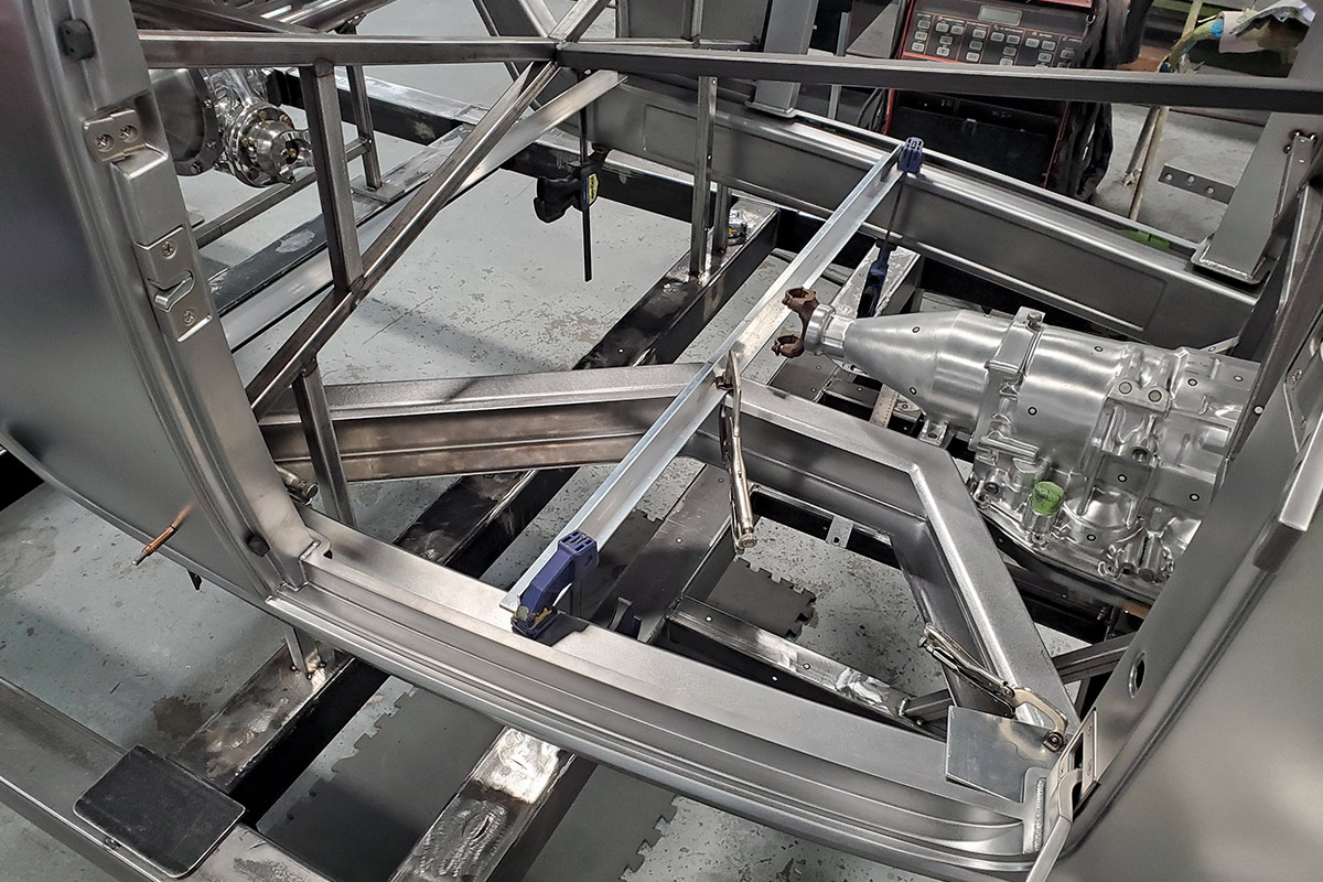
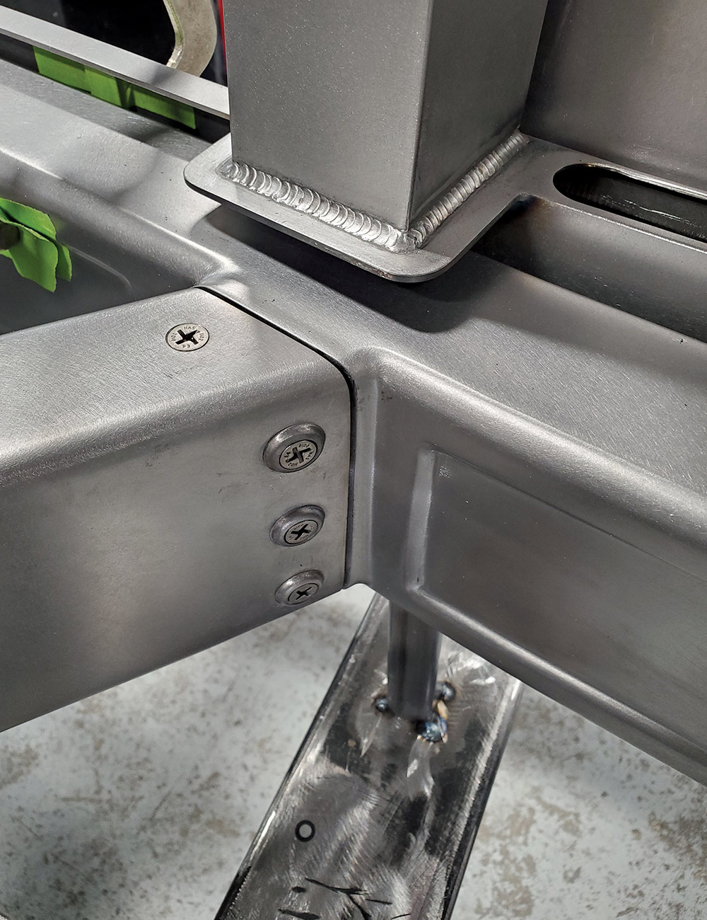
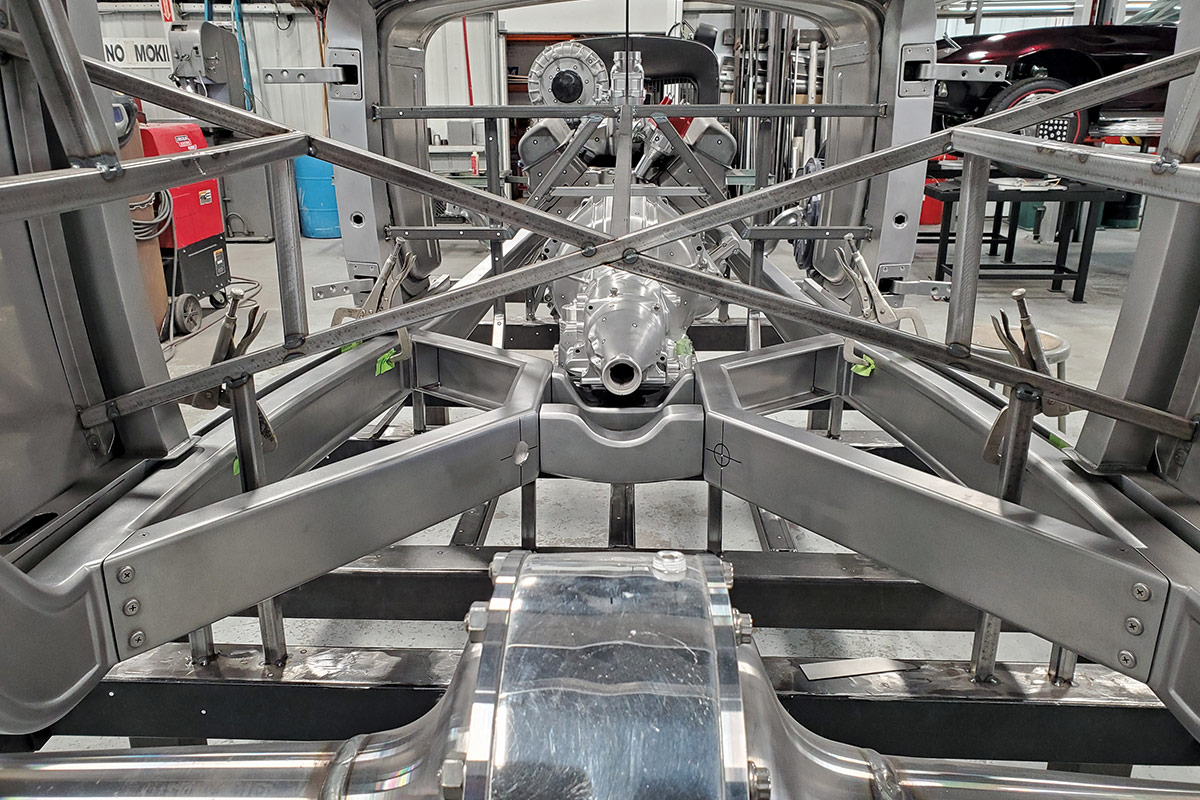
Another unusual feature this car has is a removable X-member. This was done to ease the job of painting and detailing every square inch of the chassis to an impeccable level. If you’ve ever tried spraying, blocking, and polishing the paint on an X-member, you can appreciate how beneficial it would be to disassemble these components, allowing much better access to all the nooks and crannies. The X-member was formed as two channels, with a length of ½-inch bar welded to the inner edges. This gives the components additional strength and a more-finished look.

Torq-Set aircraft-grade fasteners are used to hold these components together. Troy has used these on some of the Bonneville cars he has built, and they are made to extremely high standards for both fit and strength.

We think you’ll love seeing all the detailed work being lavished on this car, and you can look forward to many more articles showing the later stages of construction.

Hand touching a grille that is laying on the ground
1. The first step in building the custom grille was making templates for the curvature of the stock grille bars.
Three grille bars laying on a stand
2. Each grille bar made from ⅛x¾-inch cold-finished steel bar. The curve was made by shrinking the back edge. Heat was required at the bottom of the bar to attain the tighter curvature.
brace in the shape of a rounded v, laying on a metal table
3. Special braces were laser-cut to hold all the bars in registration. The notches were sized to be a snug fit on each bar.
The frame of the grille starting to be assembled on a metal table
4. The center bar was made from 16-gauge steel sheet, bent into a channel, and curved to the proper contour.
The grille bars being placed into the frame while its laying on a metal table
5. Each bar was meticulously fitted, then trimmed for a precise fit.
The new grille laying beside the old one in comparison
6. Here’s a side-by-side comparison of the new grille with the original. You can see the new grille has been sectioned considerably.
Curved metal station clamped to the top of the new grille while it's propped up on a stand
7. Curved stations have been temporarily attached to the top of the grille, to guide the shaping of the cap for the assembly.
New side panel clamped onto the grille with the station
8. New sides were made, too. Note the carefully embossed linework on the panels.
The new chin metal clamped to the grille
9. New sheetmetal was shaped to make the “chin” portion of the grille shell.
An inside view of the grille assembly
10. The ⅛-inch steel was carefully fitted to the back portion of the grille assembly, giving it plenty of stiffness. You can see how beautifully all the pieces fit together.
The grille placed on the chassis temporarily
11. With the grille held temporarily in place on the chassis table, you can appreciate just how gorgeous it is. With the key body components positioned, the chassis layout can begin.
The partially complete car frame on a stand with chipboard where the framerails will be installed
12. Chipboard is used to mock up the shape and location of the framerails. Great care is taken to make sure that all the shapes blend well together.
Close up of a special forming die machine
13. The bottom edge of the framerails will have a raised rib, reminiscent of a ’32 Ford frame. These are special forming dies made for the Pullmax, which will make this detail.
Front portion of the frame laying on a metal table
14. The front portion of the frame has been run through the forming dies.
Two pieces of the frame laying side by side on a metal table
15. After careful consideration, a decision was made to taper the height of the rib as it progresses toward the front of the framerails.
The partially complete body of the car on a stand
16. The center portion of the framerail was shaped in a similar manner, and here it’s being test-fitted to the body.
Close up of the rear portion of the car showing the rear kick up
17. The rear kick-up of the frame was formed separately and seamlessly joined to the front portion of the rails.
Two pieces of the frame laying on a metal table with tools laying next to them
18. The top and bottom flanges of the frame are shaped and tack-welded into place.
A boxing plate laying on a metal table
19. The inner boxing plates were given some tasty detailing with the Pullmax, too.
Above view of a boxing plate laying on a metal table
20. This is the boxing plate for the center of the framerail. Note that flat platforms were provided for attaching the removable X-member.
A framerail clamped in place on top of a table
21. With all the components for each framerail tack welded together, the assembly is positioned in a sturdy fixture and carefully TIG welded together.
X-member laying on top of a metal table
22. The X-member was formed as two separate channels. Here you can see the intricate bolted endcaps that will allow disassembly.
X-member in place in the frame after being welded
23. Each portion of the X-member is accurately positioned and tack welded to the framerails.
A close-up of the junction of the X-member and the frame
24. Here’s a close-up of the junction of the X-member and the frame. The quality of fabrication is superb from every angle.
Close up of the framerails
25. With the framerails completed, the attachment of the body and the fitting of the floor panels can begin.
Front view of the body, chassis, and drivetrain assembled
26. Looking toward the front, you can see how beautifully the body, chassis, and drivetrain fit together.
SOURCE
Rad Rides by Troy
(815) 468-2590
radrides.com
Modern Rodding
VOLUME 5 • ISSUE 41 • 2024