Modern Rodding Tech

InTheGarageMedia.com
Roadster
Revival
Help a Hurtin’ Highboy

1. We have a slight change to an old expression. “What you see is what you get … and then some!” truly applies with this project–and it’s not all good.

1. We have a slight change to an old expression. “What you see is what you get … and then some!” truly applies with this project–and it’s not all good.
Roadster Revival
Help a Hurtin’ Highboy

By Ryan Manson Photography by Rob Fortier

I

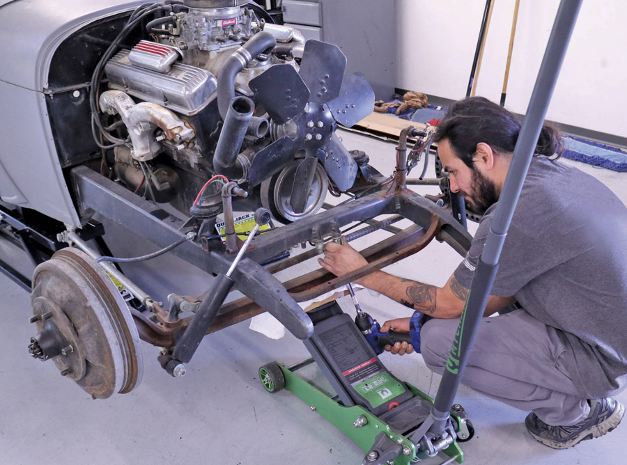
t should come as no surprise to anyone who’s purchased an incomplete project that a myriad of surprises, disappointments, and setbacks can often materialize. This ’29 Ford roadster is a perfect case study for such a situation. At first glance, it appears to be a neat traditional roadster, but upon closer inspection it starts to show its true self, warts and all.

That nice, new paint could hide lackluster metalwork. That running small-block Chevy could have 300,000 miles. The electrical system could be held together with wire nuts and duct tape. It truly is a “buyer beware” world out there, but sometimes the dream can gloss over the deal and we end up with a project that we probably should have simply walked past.

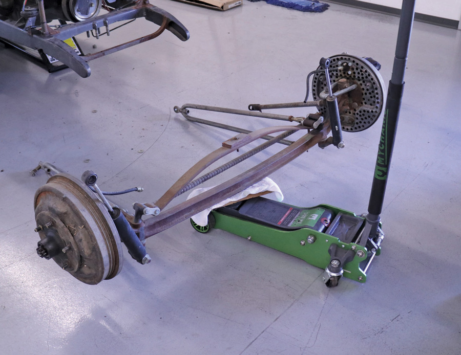
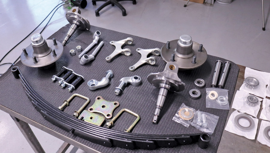
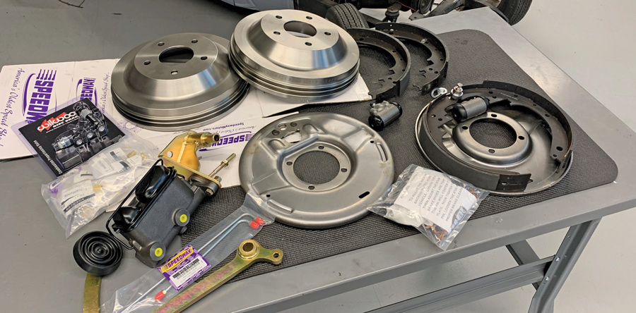
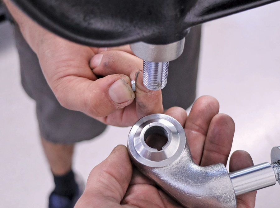
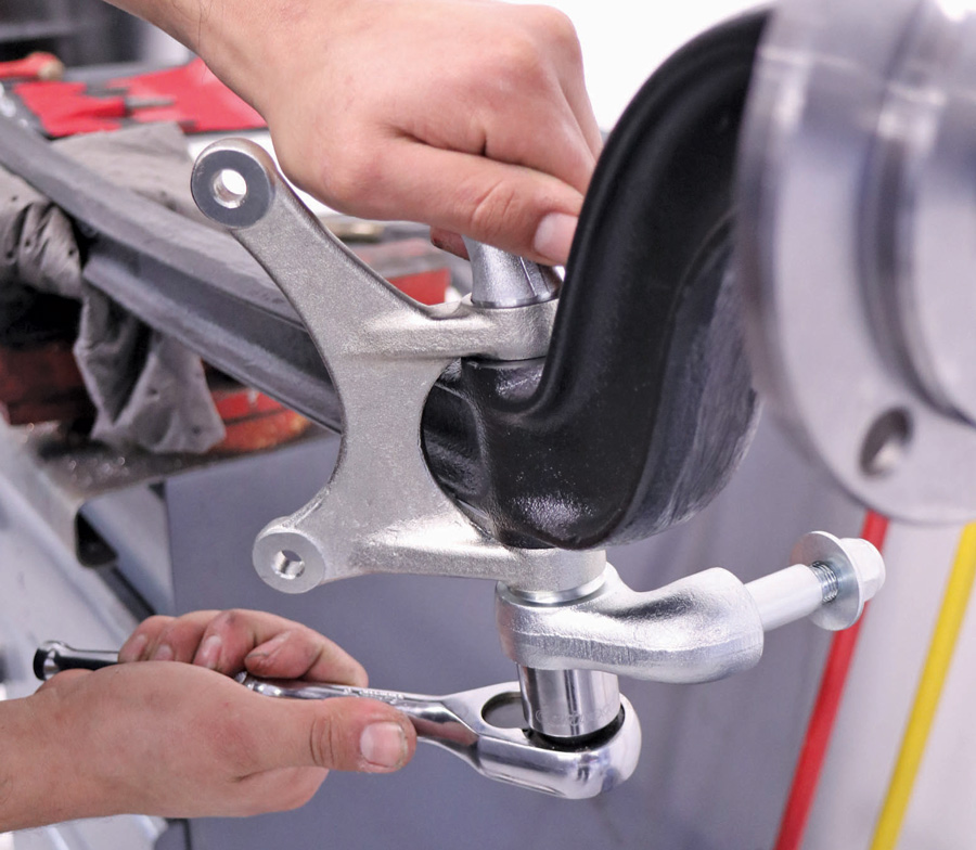
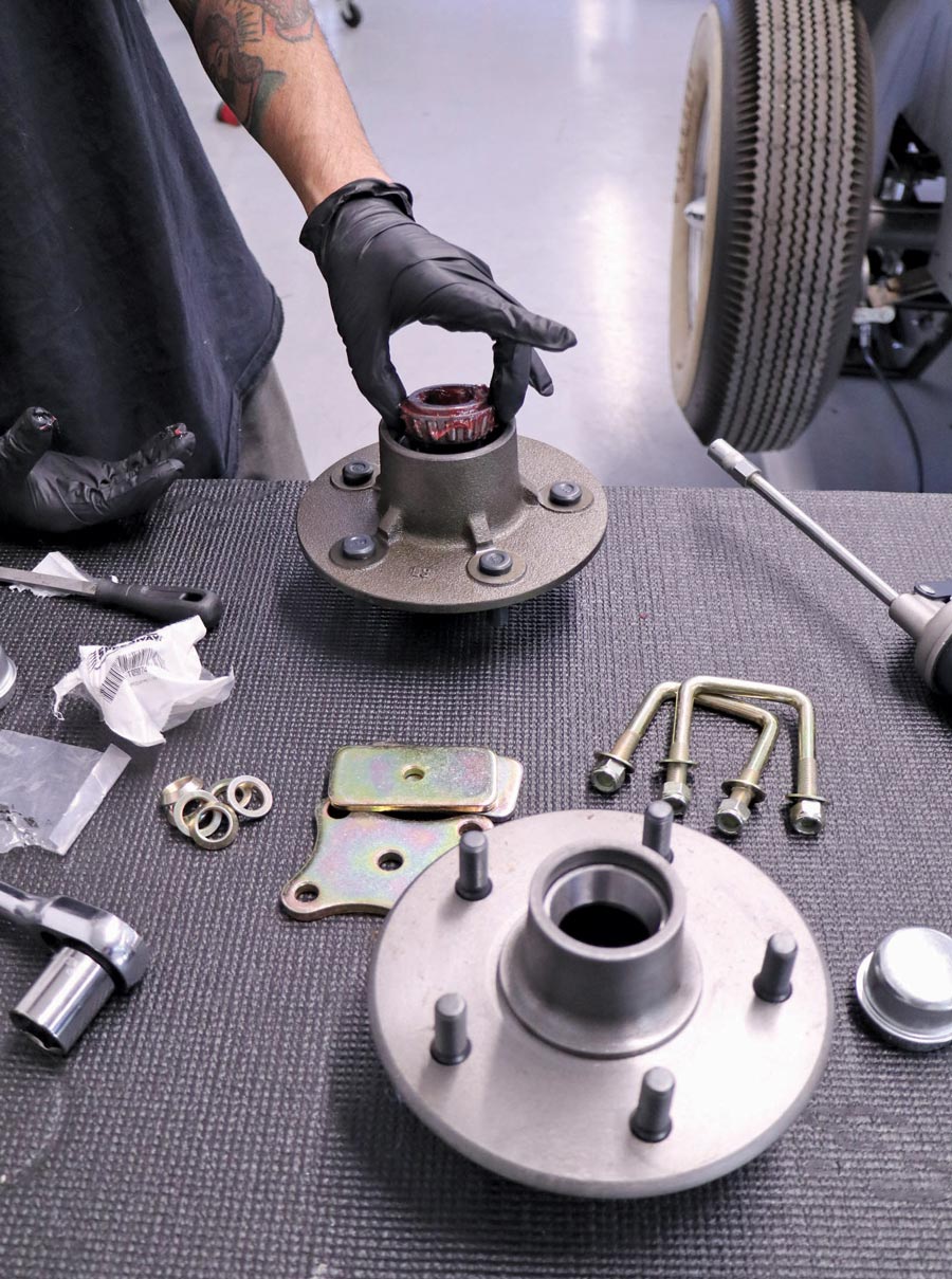
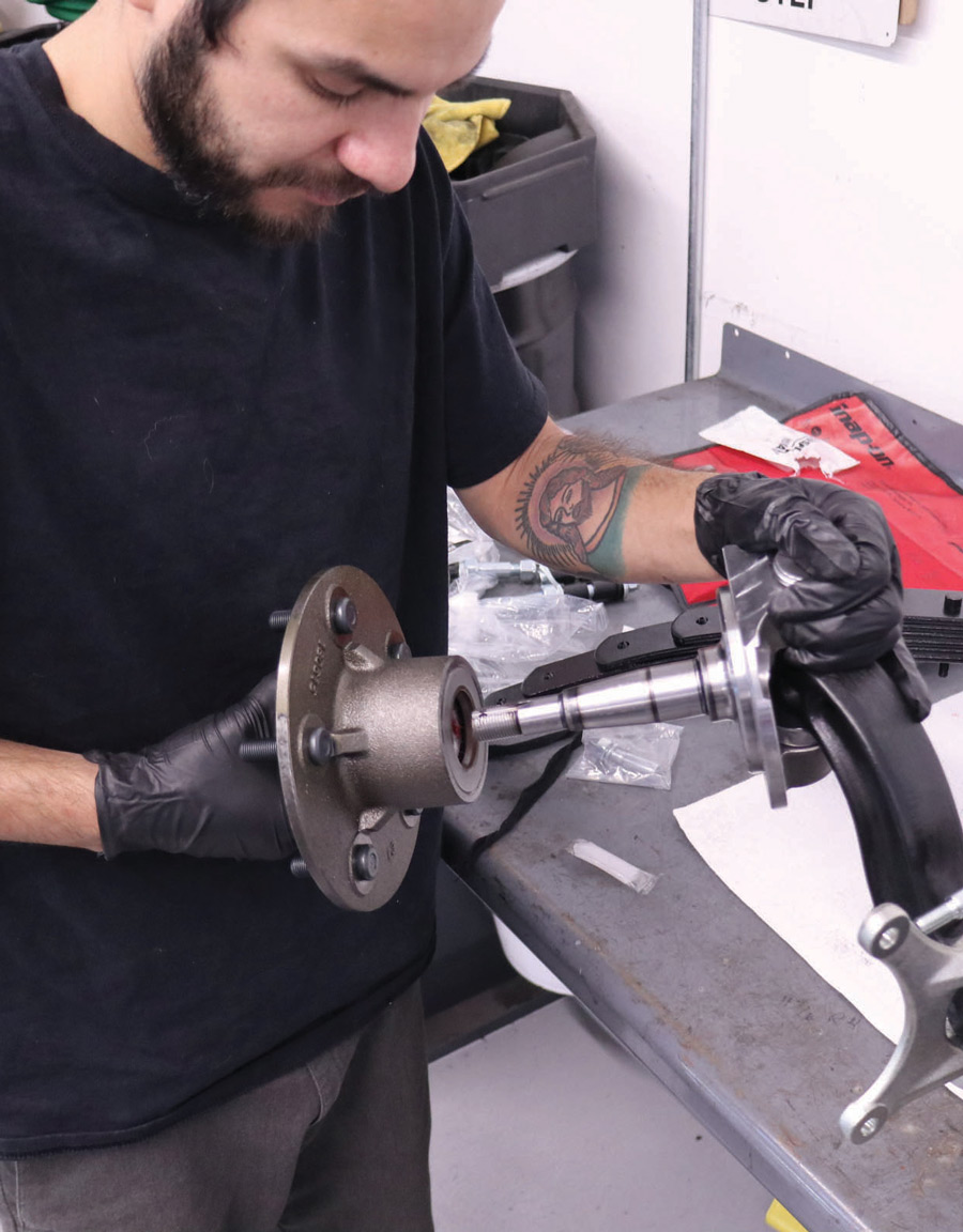
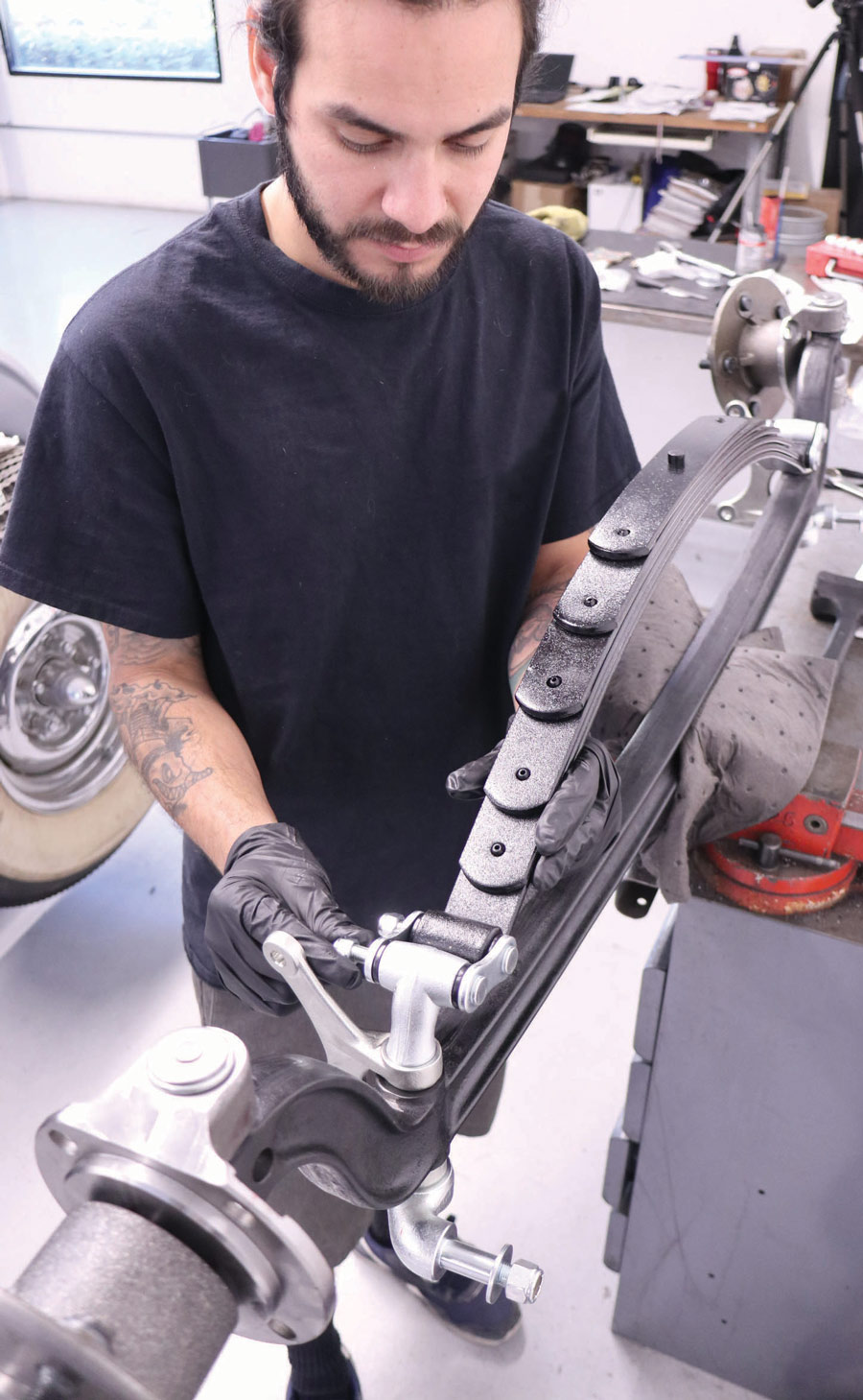
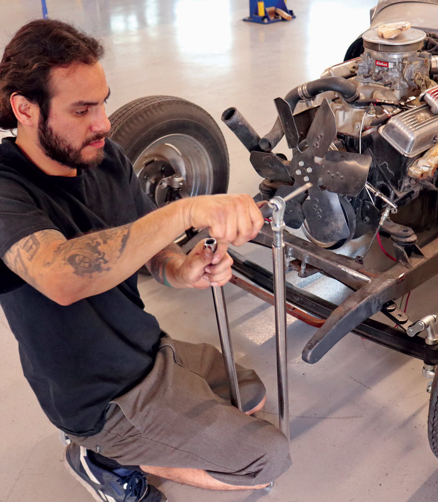
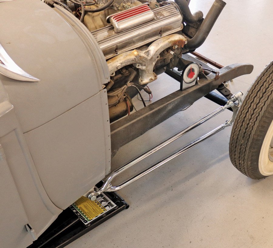
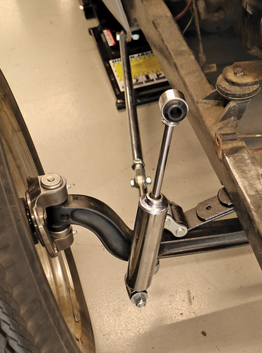
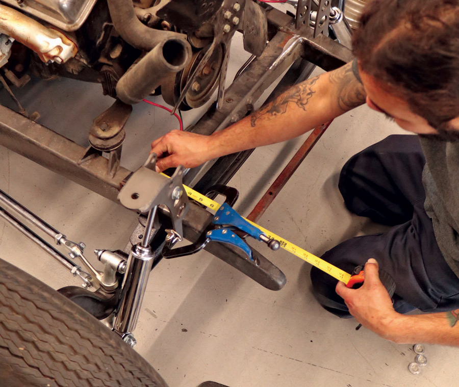
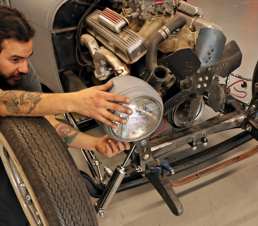
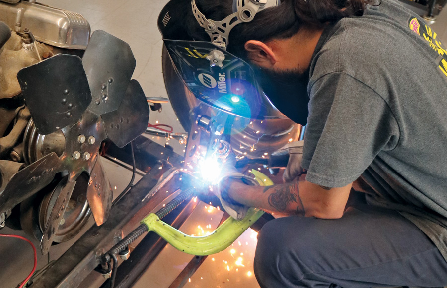
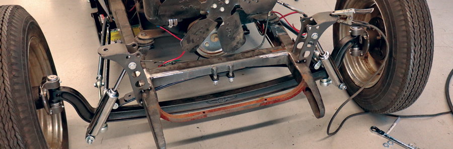
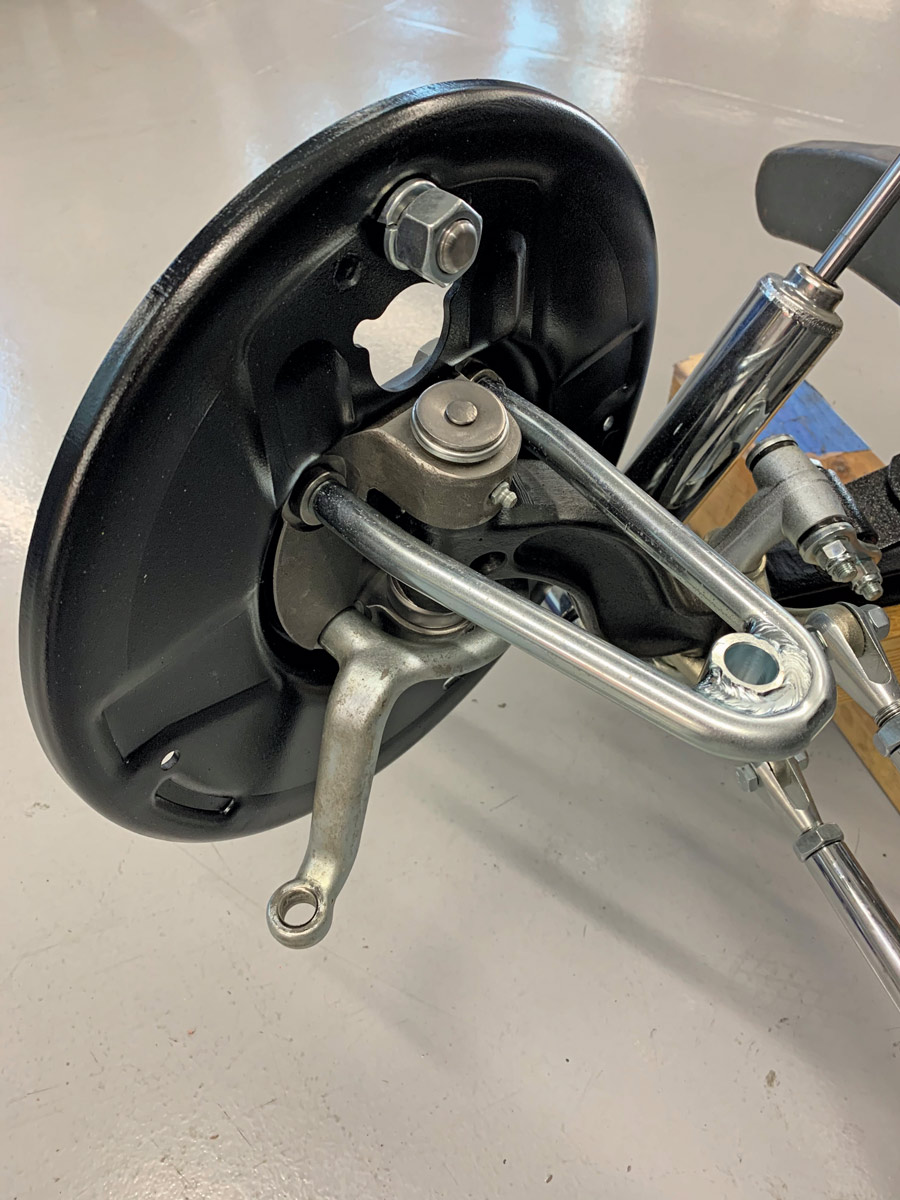
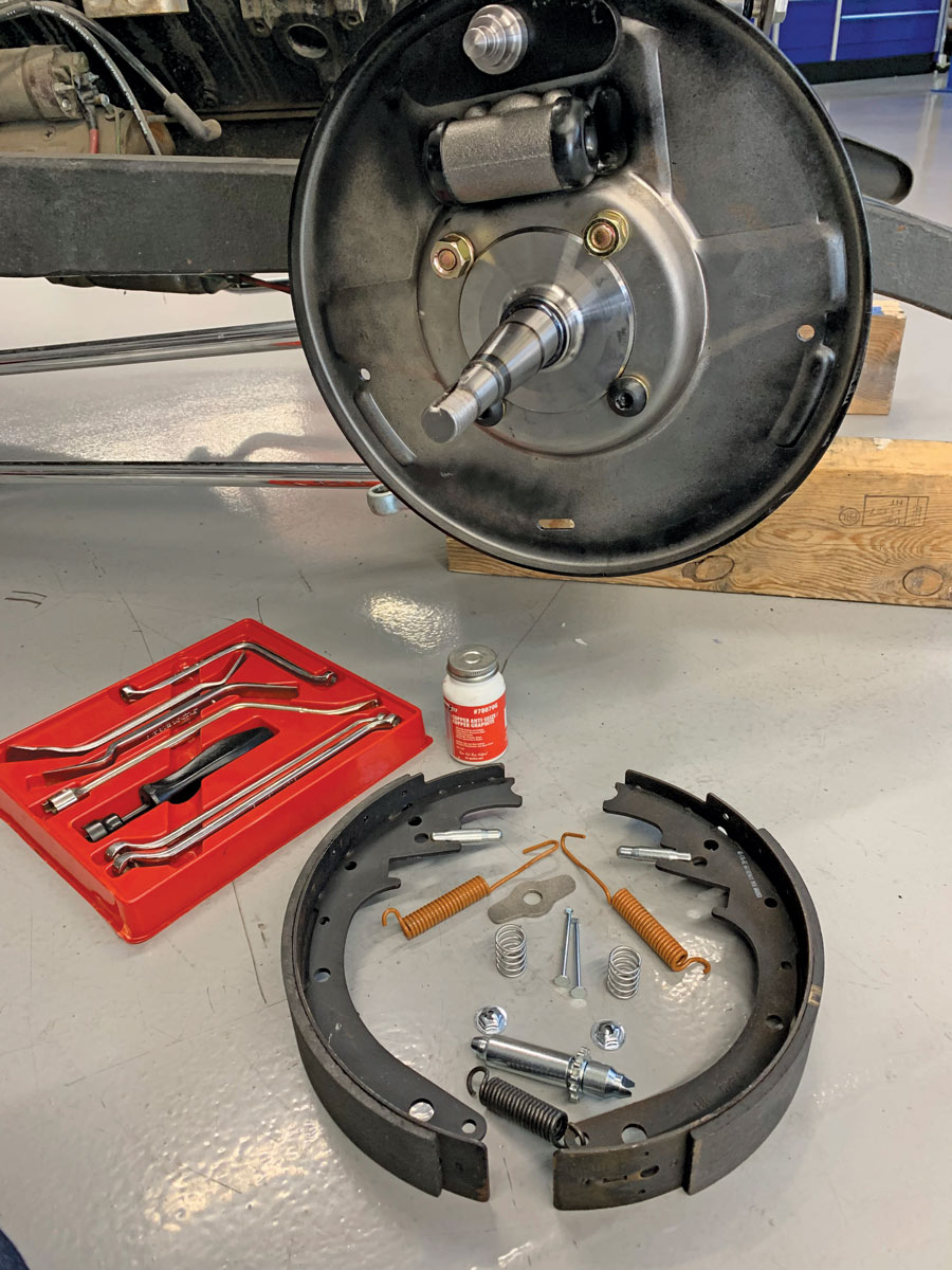
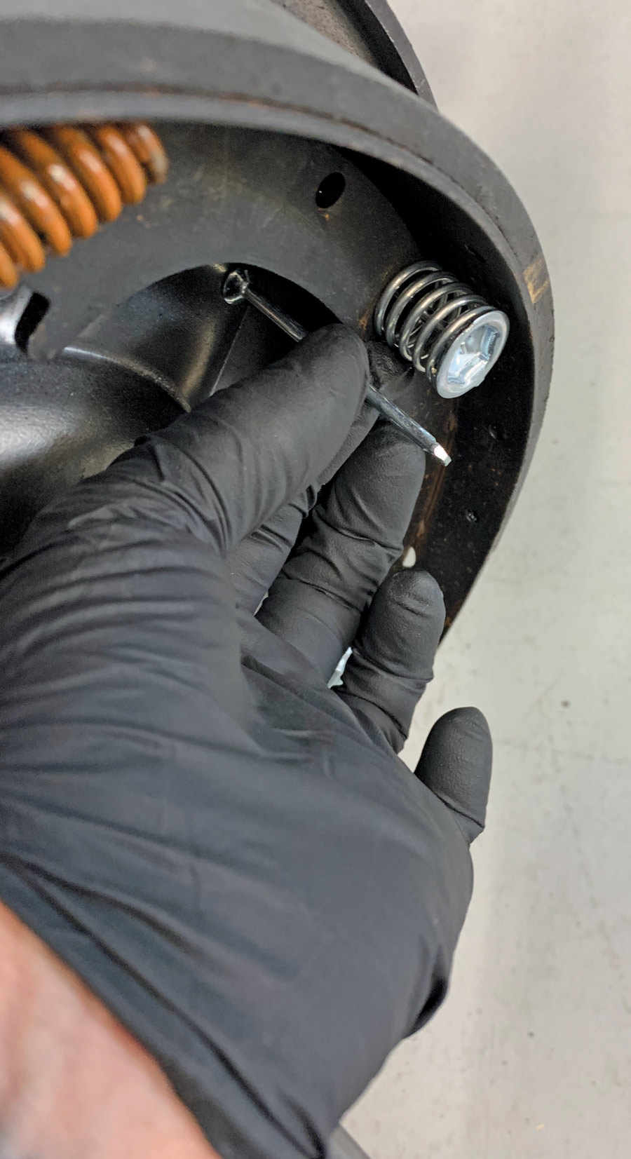
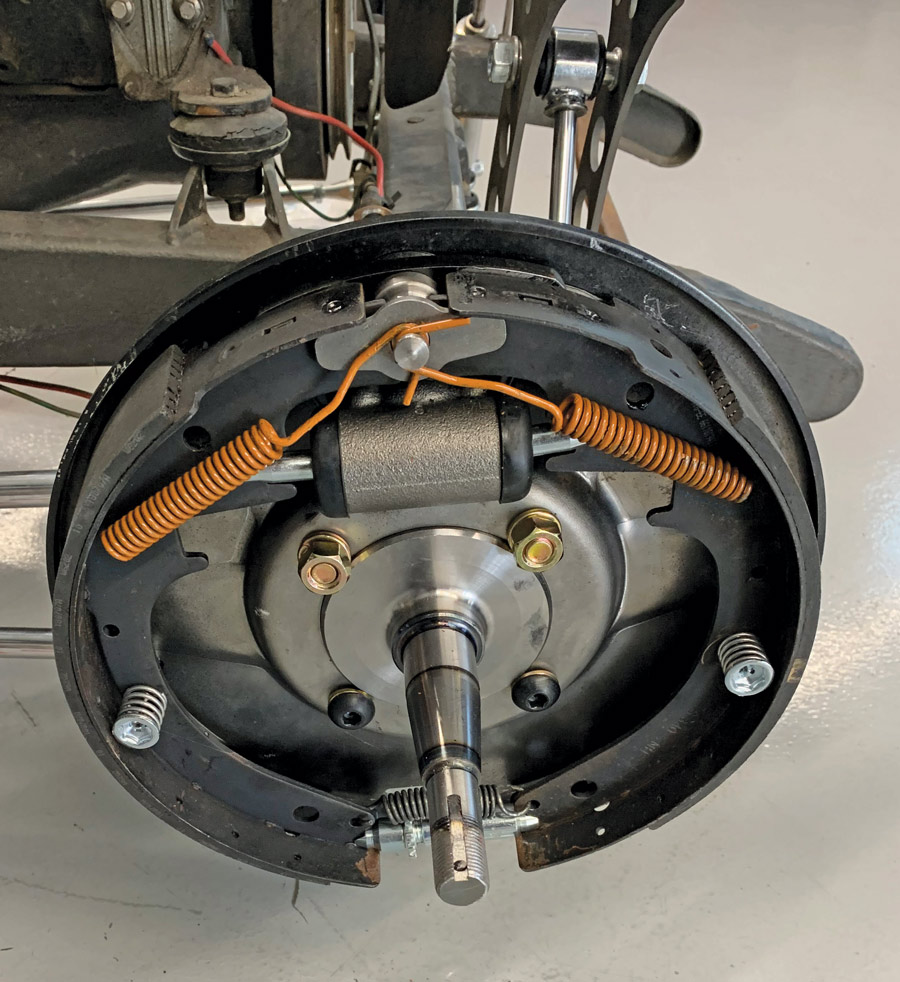
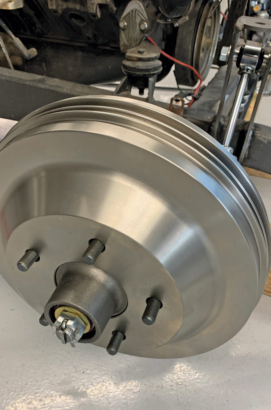
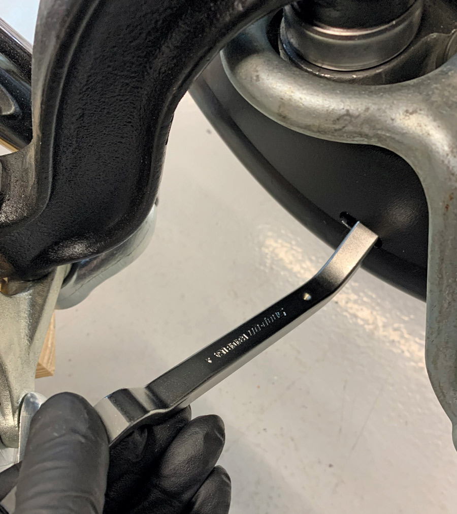
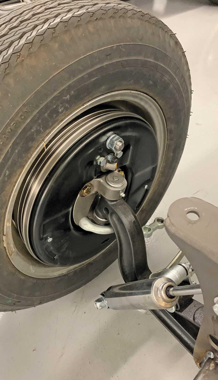
Not wanting to completely cast the A-bone aside, we decided to forge a path forward, save for some of the more questionable components. It just so happens that those components are also the parts most related to the safe operation of such a car—brakes, steering, and suspension. With that in mind, we turned to the capable crew at Speedway Motors for some much-needed guidance when it came to the direction in which we should take this roughshod roadster. We opted to tackle the most important aspects first, starting with the frontend. The guys at Speedway recommended their 4-inch dropped axle kit, a set of Bendix-style brakes, shocks and shock mounts, and a handful of other small parts to get our “A” back on the road safely.

While we found more than a handful of items left to tackle before our roadster is roadworthy, it doesn’t mean a project like this should be completely ignored. As long as there are shops like Speedway Motors around offering replacement parts for these early Fords, we can continue to upgrade and improve these old cars and keep them on the road, safely, for another hundred years!

Here’s what the project ’29 looked like when we started. It sat OK, but upon closer look it became clear that we needed to sort out a few things when it came to the brakes and suspension.
2. Here’s what the project ’29 looked like when we started. It sat OK, but upon closer look it became clear that we needed to sort out a few things when it came to the brakes and suspension.
The front end of the roadster sat on a dropped axle of questionable origin and a monoleaf spring that had either been de-arched or was plain ol’ wore out, which explains why the roadster sat so low. A homemade draglink and tie rod handled the steering duties, while a pair of “vented” Ford hydraulic drum brakes were responsible for providing stopping power.
3. The front end of the roadster sat on a dropped axle of questionable origin and a monoleaf spring that had either been de-arched or was plain ol’ wore out, which explains why the roadster sat so low. A homemade draglink and tie rod handled the steering duties, while a pair of “vented” Ford hydraulic drum brakes were responsible for providing stopping power.
The front shock mounts serve as an example of a larger looming problem that plagued the roadster: Bad welds and lack of quality build abounds.
4. The front shock mounts serve as an example of a larger looming problem that plagued the roadster: Bad welds and lack of quality build abounds.
With the original frontend removed, our righthand-shop-man Christian Arriero proceeded to axe the crooked shock mounts into oblivion.
5. With the original frontend removed, our righthand-shop-man Christian Arriero proceeded to axe the crooked shock mounts into oblivion.
To replace the original components, we opted for a Model A 46-inch Radius Rod I-Beam Axle Kit (PN 91639519) from Speedway Motors in addition to a new set of spindles (PN 91032104) and hubs (PN 91065450). The 4-inch dropped I-beam axle and super-slide reversed-eye spring will put the roadster back in the weeds but will do so with an increased measure of safety.
6. To replace the original components, we opted for a Model A 46-inch Radius Rod I-Beam Axle Kit (PN 91639519) from Speedway Motors in addition to a new set of spindles (PN 91032104) and hubs (PN 91065450). The 4-inch dropped I-beam axle and super-slide reversed-eye spring will put the roadster back in the weeds but will do so with an increased measure of safety.
In addition to the new front end, we’re going to upgrade the front brakes with Speedway’s 12-inch Bendix-Style Drum Brakes (PN 91065420), Brake Drums (PN 91065400), and a Master Cylinder/Pedal Assembly for Model T, A, and '32 Fords (PN 91631926).
7. In addition to the new front end, we’re going to upgrade the front brakes with Speedway’s 12-inch Bendix-Style Drum Brakes (PN 91065420), Brake Drums (PN 91065400), and a Master Cylinder/Pedal Assembly for Model T, A, and ’32 Fords (PN 91631926).
Arriero begins the frontend assembly by installing the new spindles and kingpins on the 4-inch dropped axle. Note the top of the spindle has been modified to fit the Bendix-Style brake backing plates.
8. Arriero begins the frontend assembly by installing the new spindles and kingpins on the 4-inch dropped axle. Note the top of the spindle has been modified to fit the Bendix-Style brake backing plates.
When it comes to installing early Ford spindles, install the bearing with the seam facing down, not up (as shown here). This prevents moisture intrusion into the bearing.
9. When it comes to installing early Ford spindles, install the bearing with the seam facing down, not up (as shown here). This prevents moisture intrusion into the bearing.
lower shock mounts install under the bat wing
installing the shock mounts
10-11. The Speedway lower shock mounts install under the bat wing on the spring perch bolt and utilize a keyway to prevent the shock mount from rotating.
Next, the wheel bearings are packed with high-temp grease ...
12. Next, the wheel bearings are packed with high-temp grease …
… and the hub assemblies installed on the spindles. Note the seal on the back of the hub to keep the grease in and the dirt and road grime out.
13. … and the hub assemblies installed on the spindles. Note the seal on the back of the hub to keep the grease in and the dirt and road grime out.
After  Arriero installs the reversed-eye super-slide spring, it’s time to slide the axle assembly under the roadster.
14. After Arriero installs the reversed-eye super-slide spring, it’s time to slide the axle assembly under the roadster.
With the axle assembly installed under the Model A’s frame,  Arriero installs the clevis ends on the chromed Speedway radius rods and adjusts them evenly.
15. With the axle assembly installed under the Model A’s frame, Arriero installs the clevis ends on the chromed Speedway radius rods and adjusts them evenly.
They are then bolted onto the Speedway bat wings and adjusted so the provided frame bracket can be welded in place.
16. They are then bolted onto the Speedway bat wings and adjusted so the provided frame bracket can be welded in place.
A pair of chromed Speedway Gas-Filled Short Tube Shocks (PN 91046222) will replace the old dampers and will mount off a pair of Speedway Weld-In Shock/Headlight Mount Brackets (PN 91036003).
17. A pair of chromed Speedway Gas-Filled Short Tube Shocks (PN 91046222) will replace the old dampers and will mount off a pair of Speedway Weld-In Shock/Headlight Mount Brackets (PN 91036003).
 Arriero attaches the shock to the mount bracket and then clamps the bracket securely to the frame. A few measurements are then made to ensure the two brackets are even and straight.
18. Arriero attaches the shock to the mount bracket and then clamps the bracket securely to the frame. A few measurements are then made to ensure the two brackets are even and straight.
 Next, a spare headlight is used to double-check the bracket’s position ...
19. Next, a spare headlight is used to double-check the bracket’s position …
Welding a bracket
Bracket in place
20-21. … before they’re tack welded in place.
The roadster was set up with a side steer box and the plan is to stick with that design. A pair of Speedway 3-3/4-inch Dropped Steering Arms (PN 7022756) will link the two front wheels while providing clearance for the tie rod, while a Hoop-Style Steering Arm (PN 7204010) will mate the driver side spindle to the draglink.
22. The roadster was set up with a side steer box and the plan is to stick with that design. A pair of Speedway 3-3/4-inch Dropped Steering Arms (PN 7022756) will link the two front wheels while providing clearance for the tie rod, while a Hoop-Style Steering Arm (PN 7204010) will mate the driver side spindle to the draglink.
The Bendix-style backing plates are installed at the same time as the steering arms, save the internal components, along with the anchor pin and wheel cylinder. At this point, the anchor pin is left slightly loose.
23. The Bendix-style backing plates are installed at the same time as the steering arms, save the internal components, along with the anchor pin and wheel cylinder. At this point, the anchor pin is left slightly loose.
Next, the 2-inch brake shoes are installed using the star wheel adjuster and spring to temporarily hold them in place.
24. Next, the 2-inch brake shoes are installed using the star wheel adjuster and spring to temporarily hold them in place.
The Bendix brakes use a leading and trailing shoe design; the shorter-lined shoe is installed toward the front.
25. The Bendix brakes use a leading and trailing shoe design; the shorter-lined shoe is installed toward the front.
 A retaining pin, washers, and spring hold each shoe in place permanently.
26. A retaining pin, washers, and spring hold each shoe in place permanently.
The shoe retaining plate is then placed over the anchor pin and the return springs installed, completing the installation of the internal components.
27. The shoe retaining plate is then placed over the anchor pin and the return springs installed, completing the installation of the internal components.
The wheelhub is reinstalled along with the brake drum so that the brakes can be adjusted and the anchor pin tightened.
28. The wheelhub is reinstalled along with the brake drum so that the brakes can be adjusted and the anchor pin tightened.
 The brakes are adjusted using a brake adjusting tool by turning the star wheel adjuster until the shoes are tight against the drum. This serves to center the anchor pin, which can then be tightened. The star wheel adjuster is then loosened until proper brake adjustment is attained.
29. The brakes are adjusted using a brake adjusting tool by turning the star wheel adjuster until the shoes are tight against the drum. This serves to center the anchor pin, which can then be tightened. The star wheel adjuster is then loosened until proper brake adjustment is attained.
 It’s recommended to install all the components as a “dry-fit” before painting to ensure everything fits together without any interference.
30. It’s recommended to install all the components as a “dry-fit” before painting to ensure everything fits together without any interference.
SPEEDWAY MOTORS
(800) 979-0122
speedwaymotors.com
Modern Rodding

VOLUME 3 • ISSUE 17 • 2022