Modern Rodding TECH
InTheGarageMedia.com

1. Nick Sinioris at Hot Rods by Dean carefully planned out his work and then worked his plan–how’s that for a novel approach!

Another Way to Skim a Cap title image
Part 1: How to Cut the Tedious Labor Associated With Chopping a Top
By Chris Shelton Photography by Brian Brennan
T

he world really doesn’t need yet another top chop story—or so I thought. Then ol’ Editor Brian Brennan visited Dean Livermore at Hot Rods by Dean and brought home these photos on the chopping of a ’33 Ford DeLuxe coupe.

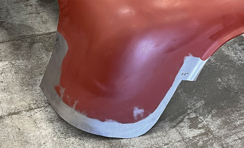
It wasn’t the chop itself that caught my attention—it’s a moderate cut (2-1/2 inches) on a somewhat common car. Rather, it was the way Nick Sinioris plotted his cut lines to minimize effort and maximize accuracy that stood out.

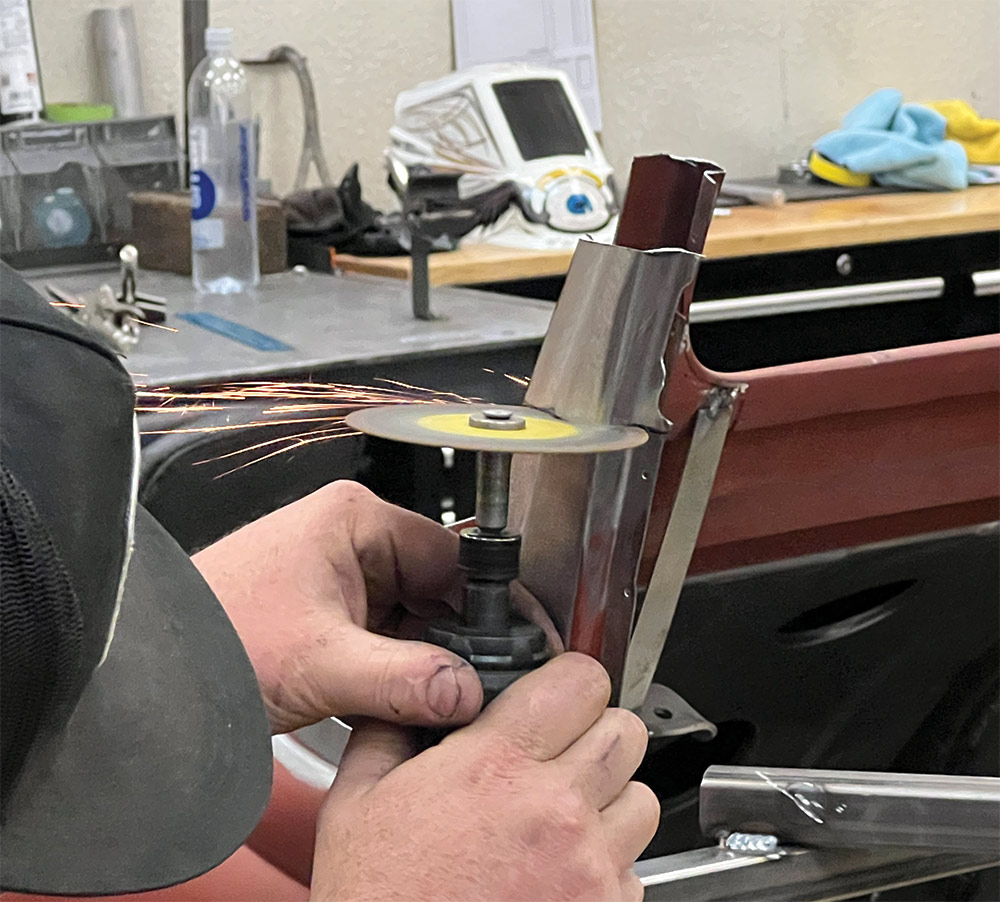
Welding—specifically the preparation for welding—really eats up time. Strong welds that don’t distort favor tight, consistent gaps. While nearly anyone can get such a gap along a short run, it takes a fair amount of skill and time to get that kind of gap over, say … a foot or 2. To get those tight, consistent gaps over that large area usually requires cutting a little wide of the scribe lines then creeping up on them with snips and files. And that kind of fit up usually requires making tabs to support the panels during the trimming process. The fit, trim, and repeat cycle takes a long time.

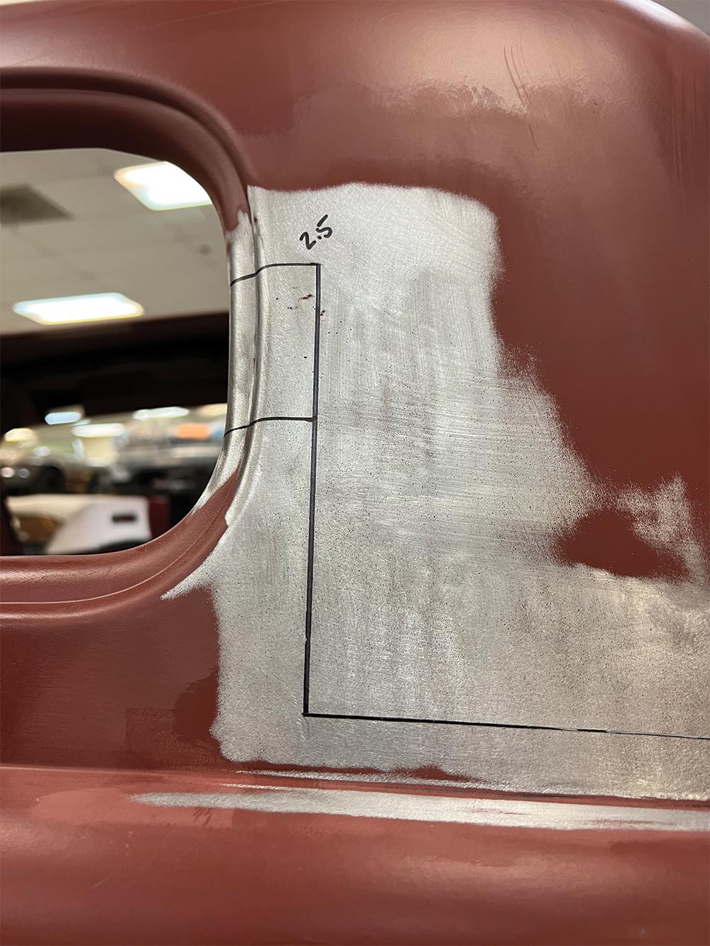
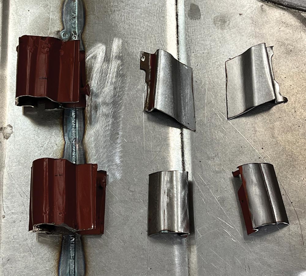
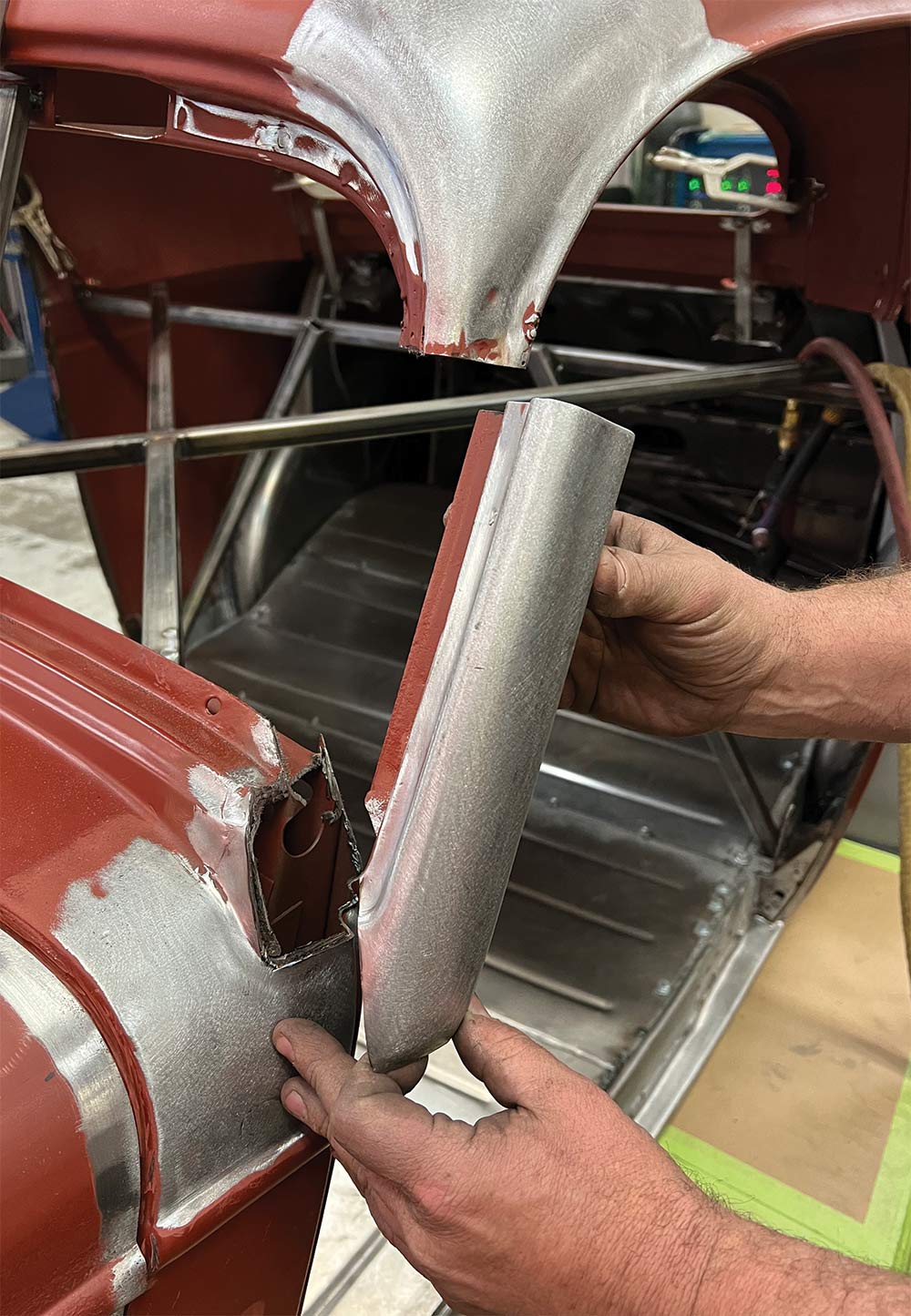
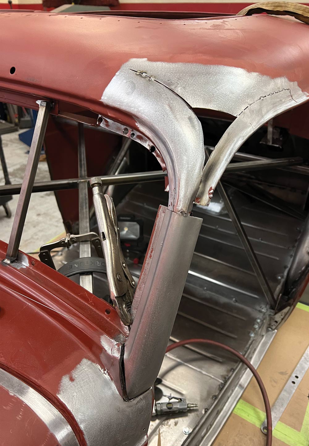
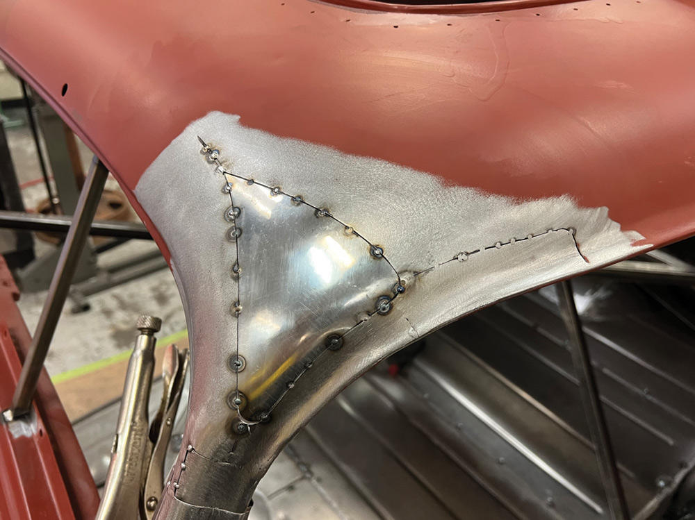
In oversimplified terms, Sinioris cut the top off, slid it down until the base overlapped the top, drilled through the overlapped area for temporary panel fasteners, then pinned everything together. That lets the lid fasten to the body without separate tabs or brackets.

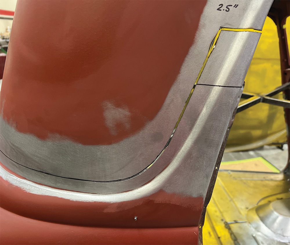
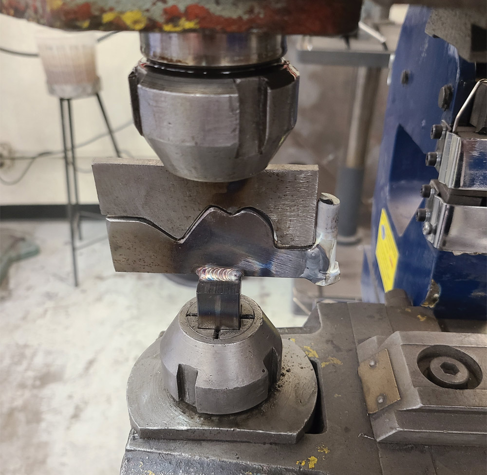
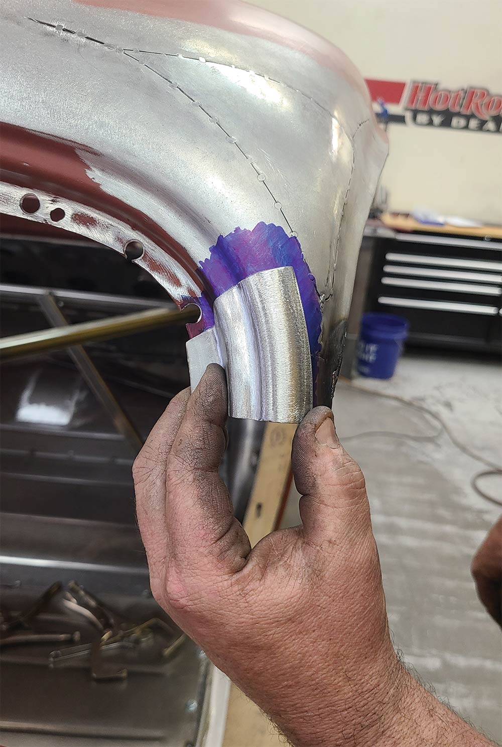
Though neat, the ability for the top to serve as its own fixture is a secondary benefit to Sinioris’ method. The cut edge of the overlapping panel doubles as a guide for scribing and/or trimming the underlying panel. Cut right on that guide or cut through both panels simultaneously and you’ll get a panel gap that measures exactly the width of the cutting blade. Close up that gap for GTAW/TIG process as Sinioris did or leave it open for GMAW/MIG.

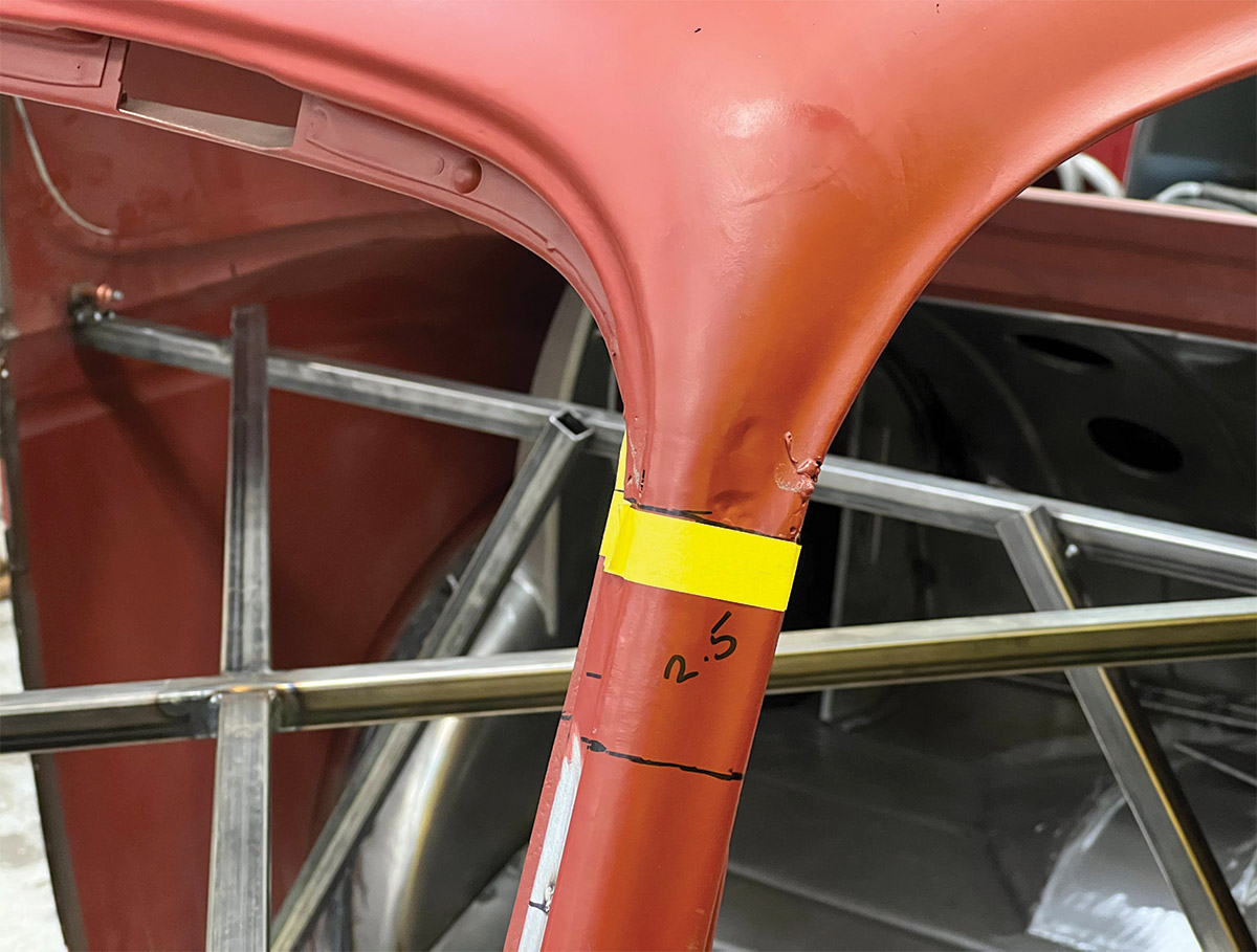
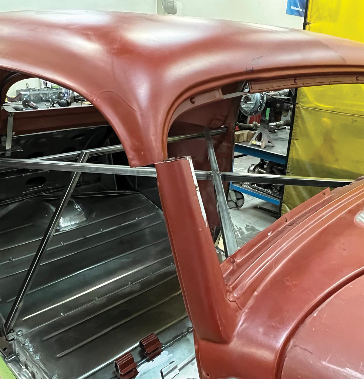
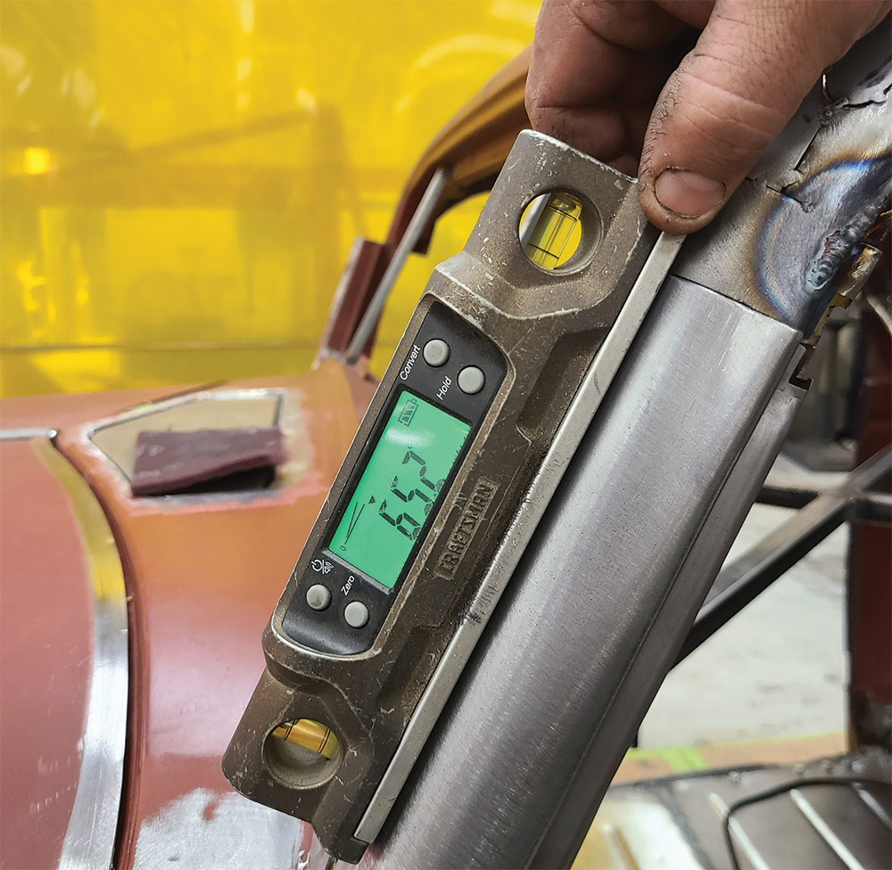
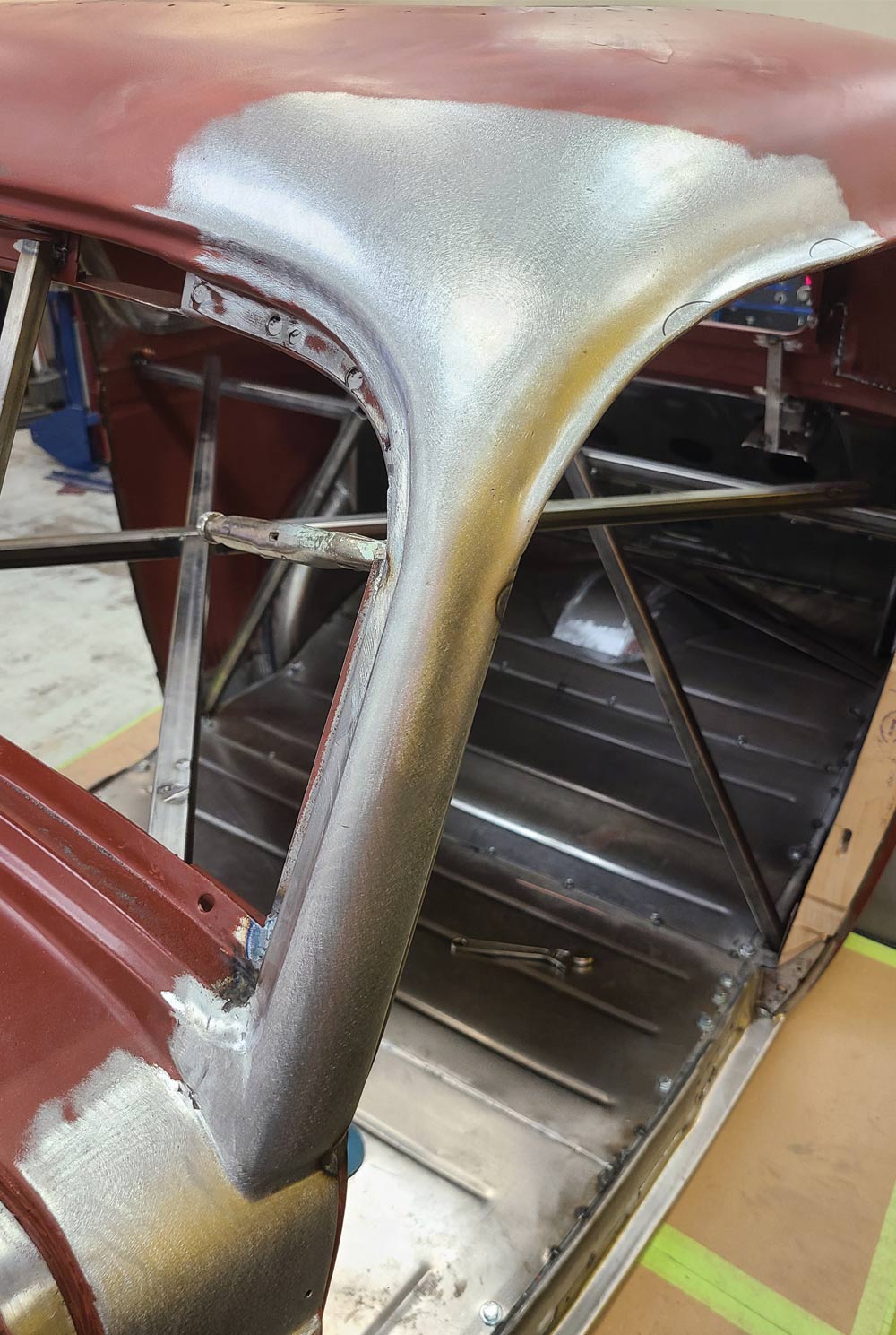
Because the top tapers toward its crown, the pillars misalign when chopped (the top emerges too short, lengthwise). One correction method extends the lid part of the top lengthwise to realign the posts. That maintains the windshield angle, which preserves the windshield’s seal.

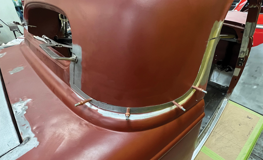
The other method leans the windshield posts back. Doing that streamlines the windshield, which made it a popular technique in landspeed racing in the middle of the last century (see the Spalding brothers’ and SO-CAL Speed Shop’s coupes for examples). You’ll sometimes hear people refer to it as a Bonneville chop, and it’s how Sinioris chopped this top.

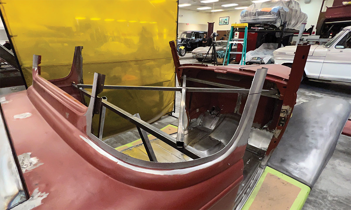
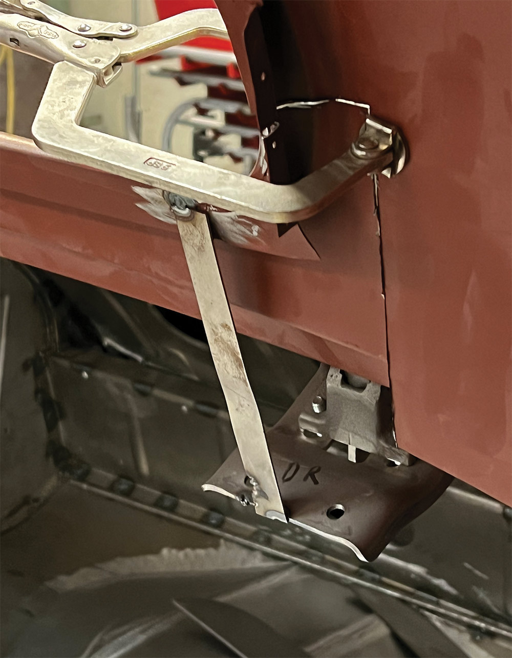
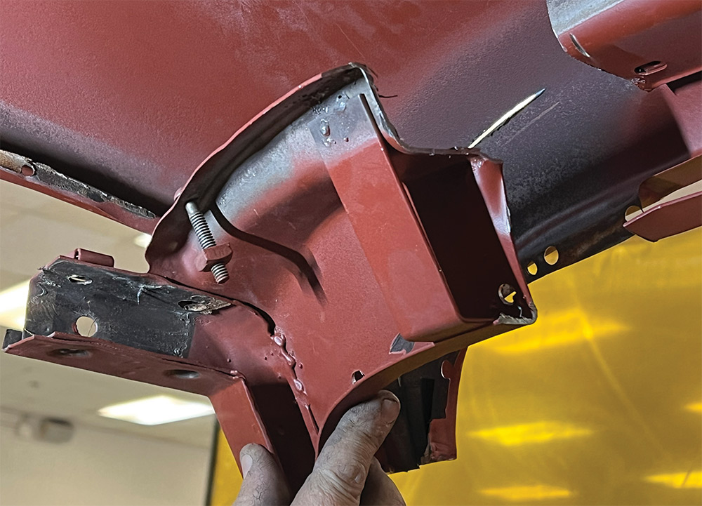
Along the way you’ll see a few other techniques that improve a chop’s integrity. For example, Sinioris uses a fixture to preserve hinge-pin alignment during reassembly, something that ensures that the doors will open and shut without binding. He also fabricated a lot of internal structural elements, like a tubular support that bridges the doorjambs and ties them into the top and inner fenderwells.

This is the first in a two-part series showing how Sinioris and the Hot Rods by Dean crew dropped a lid. Though some techniques are specific to Model 40 coupes, most of the process translates to other makes and models of the period, if only because they’re built largely the same way.

I still stand by my assertion that the world has enough top chopping stories. But as I’ve learned, for every rule there’s an exception. And so long as fabricators find those ways to improve the process and reduce the effort, we’re all eyes.

Cut lines sketched on roof
2. Sinioris plotted his cut lines at points with the least shape change. That meant horizontally through the sides of the window and just above the beltline. Connecting those two results in the vertical cut line to the right of the window.
Cut lines on rear of roof
3. The main cut line follows the bead up to the area with the least area and shape change. Note the parallel horizontal cut lines. They’re measuring 2-1/2 inches apart, the distance that the top will come down.
Cut line sketched on A-pillar
4. The smallest and simplest 2-1/2-inch section of the A-pillars hangs out just below the area where the lines straighten out. Again, note the parallel horizontal lines.
Body shell with roof removed
5. Sinioris cut along the plotted lines then removed the top. For the time being, he cut only one side of the parallel horizontal lines noted in earlier steps.
Cutting roof pillars with disc cutter
6. After removing the top, Sinioris returned to cut along the remainder of the parallel horizontal lines.
Cut pillar sections
7. These scraps represent the amount officially chopped from the rear window, side bead, and A-pillar.
Roof C-pillar after removal
8. This is how the top looked immediately after it came off the car. Note where the primer starts relative to the cut line.
Roof temporarily fastened to body
9. The crew slid the upper part of the top down into the body by 2-1/2 inches, concealing the bare area along the cut line. Then they drilled through the areas that overlapped and pinned the pieces with temporary panel fasteners. They trim the overlapped area in a later step.
Temporary roof clamp for alignment
Temporary brace for alignment
10-11. They tacked in some temporary brackets to secure the roof. They exist only for alignment.
A-pillars unaligned after chop
12. The top tapers toward its crown, and because Sinioris maintained alignment of the rear section, the A-pillars land short. Some lengthen the top to correct this.
Removing pillars entirely
13. But others change the angle of the A-pillars to realign them with the top. This is the foundation of the so-called Bonneville Chop, a design pioneered by the Spalding brothers and Alex Xydias, among others. Sinioris began by severing the pillars entirely.
Cutting inner roof structure
14. Modifying the top skin requires access to its backside. Sinioris cut away part of the inner structure at the upper corners.
Hole in roof corner to ease metal shaping
15. Sinioris then split the top skin above the windshield and above the doorjamb then pulled the top’s corners forward. He cut the pie-shaped hole to minimize interference.
Shaping piece of sheetmetal to patch roof
16. Pulling the top to meet the pillars opened gaps too wide to weld together. So, Sinioris shaped a replacement panel to fit.
Roof patch bead welded in place
17. He trimmed the panel to cover only the essential areas then used it as a template to scribe and then cut the top skin. Removing the inner structure gave Sinioris access to the panel’s back side so he could stretch the weld beads.
Pillar angle gauge showing 65.2 degrees
18. The windshield posts started life at 71.3 degrees. Now they lean back 5 more degrees to meet the top’s new location.
Press dies for power hammer
19. The windshield perimeter no longer lined up after cutting and pasting and the tight area makes it difficult to reshape. So, Sinioris made these dies to fit the power hammer.
Demonstrating retainment of original windshield radius of new roof
20. The finished product restores the gentle radius that originally made up the windshield corners.
Smoothed roof and A-pillar
21. Once welded in, the panel makes a seamless transition among the modified parts. All that remains at this point is welding the inner structure back in place.
Hot Rods by Dean
(800) 362-9709
hotrodsbydean.com
Modern Rodding

VOLUME 3 • ISSUE 27 • 2022