
Modern Rodding Tech
1957 Ford Ranchero
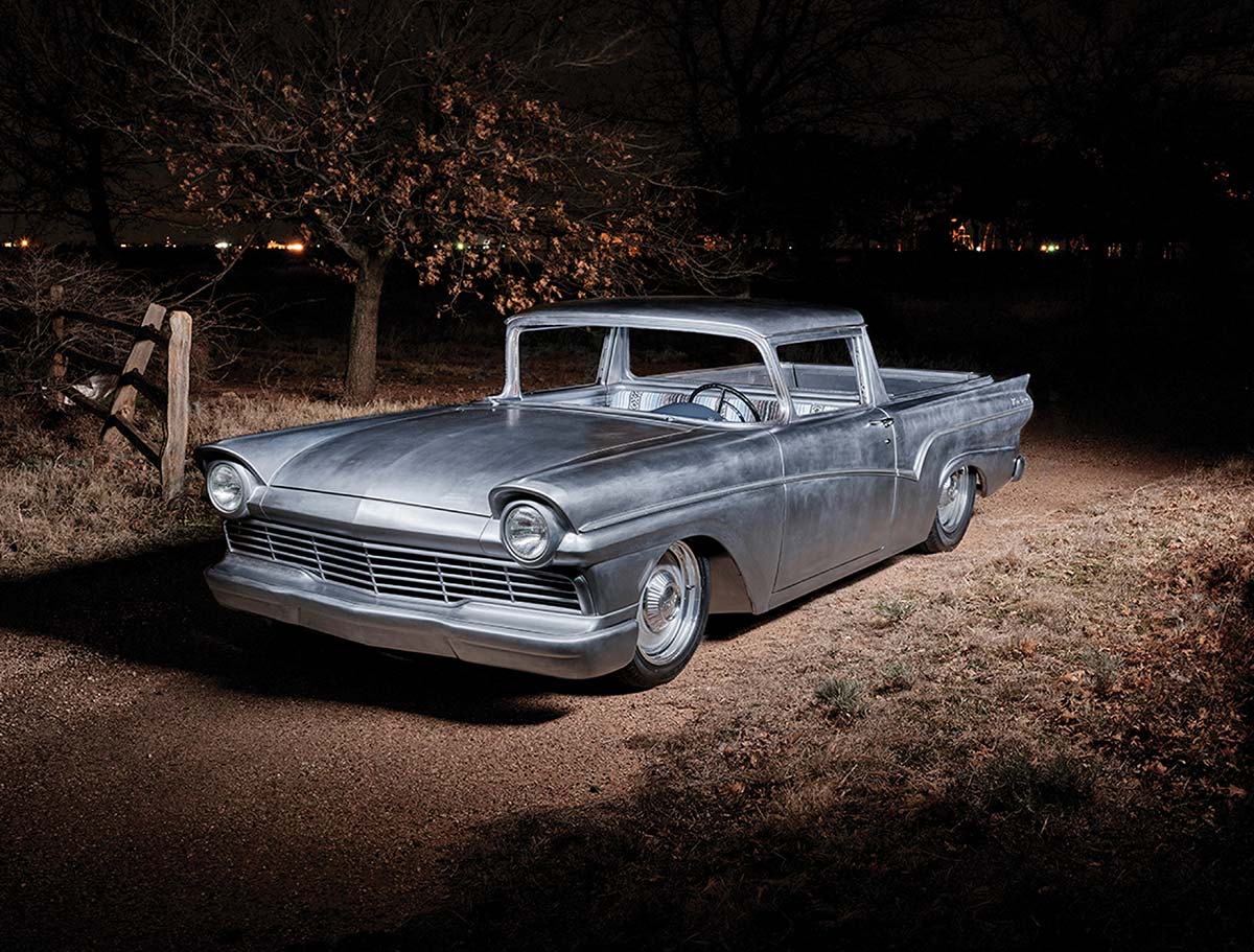
Front angle of a bare-metal 1957 Ford Ranchero project.
1. Here in part 3, we are going to learn how Brian Limberg and the crew at Tin Man’s Garage (TMG) achieved the modified stainless trim look.
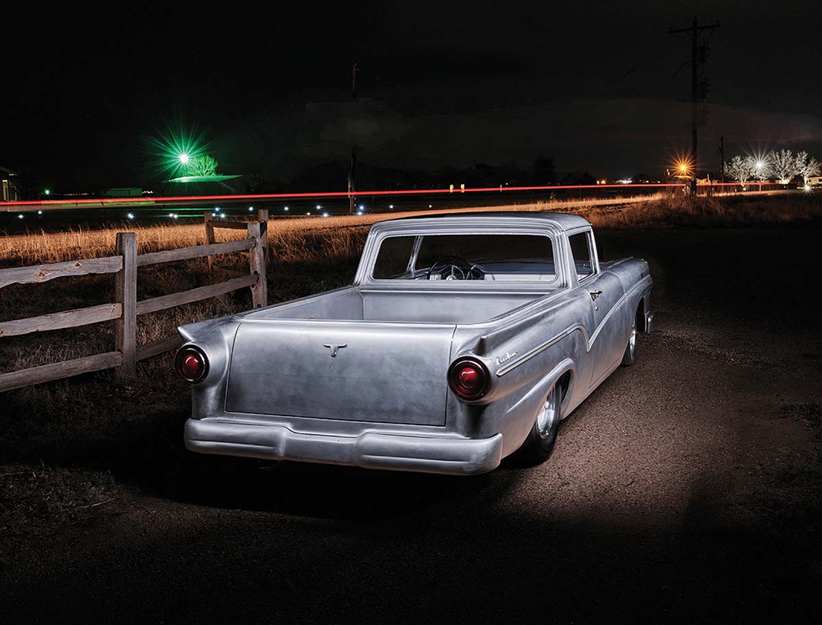
Rear quarter view of the unpainted 1957 Ford Ranchero at night.
2. It’s always very cool and informative to see a hot rod before final bodywork and paint. Here, this moody nighttime scene makes the 1957 Ford Ranchero appear ready to roll—Cool Ranch.
Part 3: How To Modify Stainless Trim
By BRIAN LIMBERG

PHOTOGRAPHY BY NOTSTOCK PHOTOGRAPHY & TIN MAN’S GARAGE

ARTWORK BY JIMMY SMITH CONCEPTS

T

he 1957 Ranchero body was derived from a basic station wagon. Specific roof sections on the quarter-panels were cut off, and other trim pieces were stamped to cap voids and conceal areas of the original body make. The modified stainless trim for this Ranchero’s bed was designed to cover the remnants of window tracks for the side windows and back glass. Most of these modifications were crude, to say the least, and the final fitment was of little concern or value.

It isn’t uncommon for major automotive manufacturers to “Frankenstein” or modify standard make-and-model vehicles to create new models. Not having to build separate stamping tooling typically saves time, which saves money.

Mike Long, the owner of this 1957 Ford Ranchero, presented the idea of making modified stainless trim to fit better rather than removing the seams and screw holes after being reminded of how poorly they fit and seeing an all-original, restored Ranchero at a car show. With numerous modifications made to this specific build to clean up the original factory design, Tin Man’s Garage dove headfirst into this project with a simple yet somehow complex process.

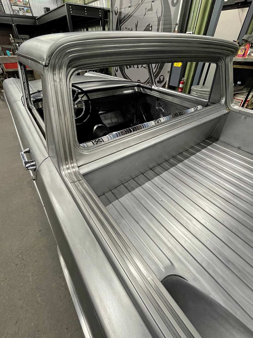
Illustration of bodywork and trim modifications for the 1957 Ford Ranchero.
3. If you have followed along, you can see what artist Jimmy Smith had in mind after listening to both Mike Long, the owner, and Limberg. And it’s coming together nicely.
Custom stainless steel bed trim fitted to the Ranchero cab.
4. Here is your goal with new, modified stainless trim in place.
Original stainless trim with holes next to new modified trim pieces.
5. The process began by filling all the screw holes in the trim, which yielded the modified stainless trim. The recessed holes were flattened, and small, stainless steel sheet metal plugs were punched. The plugs were TIG welded in place, then carefully sanded and metal finished one by one.
Clamping the stainless trim onto the body to prepare for welding.
6. The stepped flanged edges were trimmed, and the trim was clamped into its proper position on the body. Specialized dollies with caulking tools were used to make minor adjustments to prepare the fitment for tack welding.
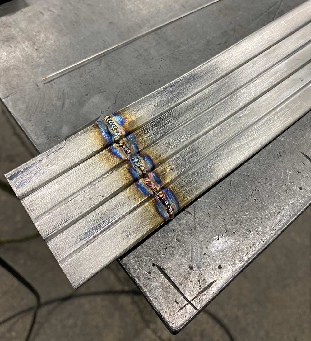
Close-up of TIG-welded seams on the custom stainless steel trim.
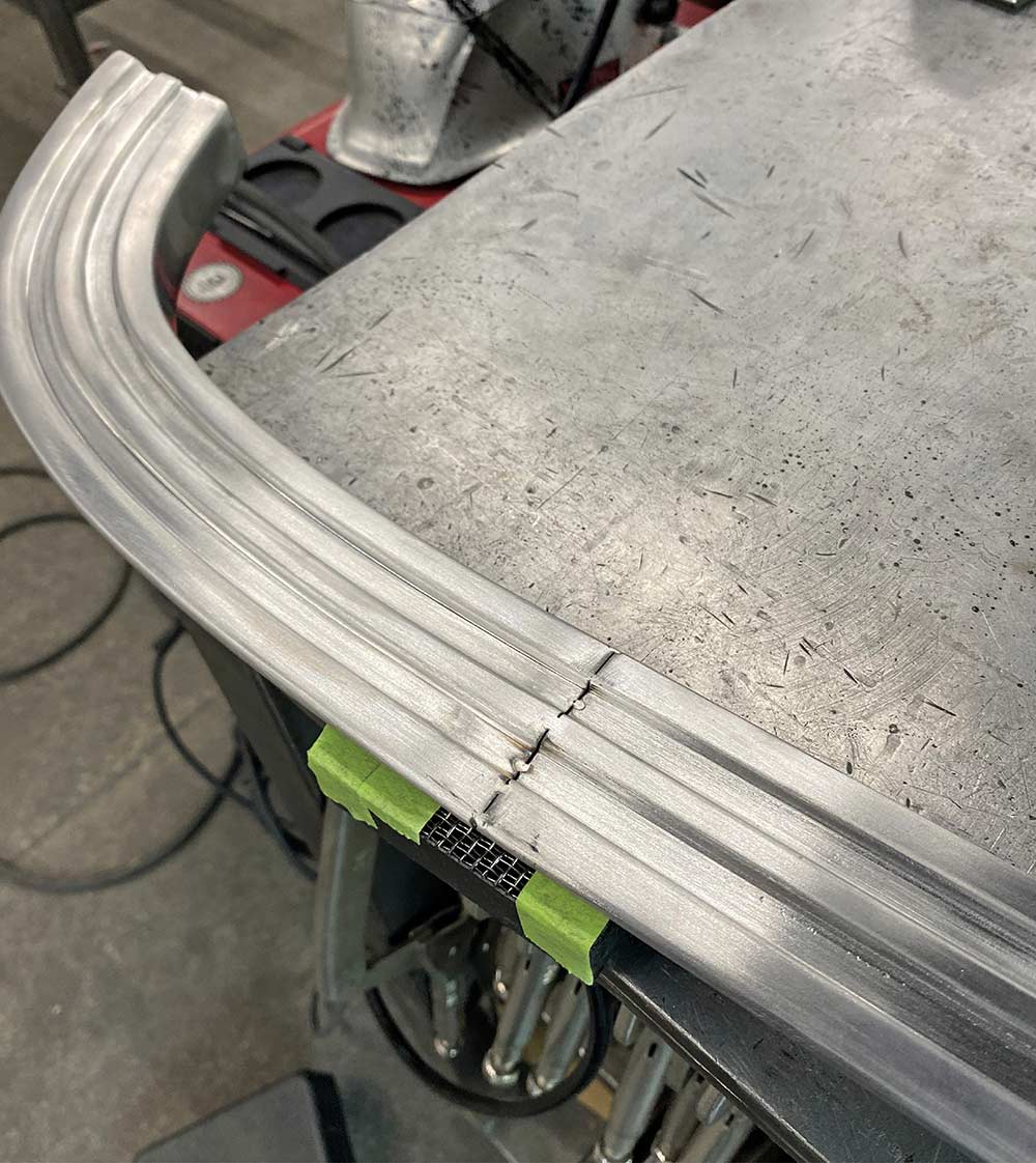
7. After the trim was tack welded, the seams were fully welded. The primary concern when welding thin modified stainless trim is to minimize heat to limit undercutting into the base metal, which makes metal finishing more difficult because it requires going back and adding weld to fill low voids.
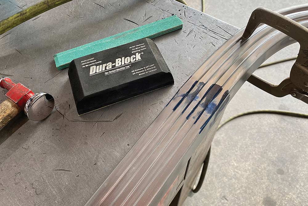
Hand-sanding the weld seams on the stainless trim with a Dura-Block.
8. Each weld seam was sanded with an 80-grit Roloc-backed disc on a 90-degree pneumatic die grinder and then blocked by hand. The lows were picked up, the highs were hammered down, and the seam was block sanded repeatedly.
Metal-finished stainless trim piece with smooth ribs and no visible holes.
9. The process continued along each of the ribs until the weld seams disappeared. This is an example of how the trim looks after the weld seams and the filled holes were metal finished.
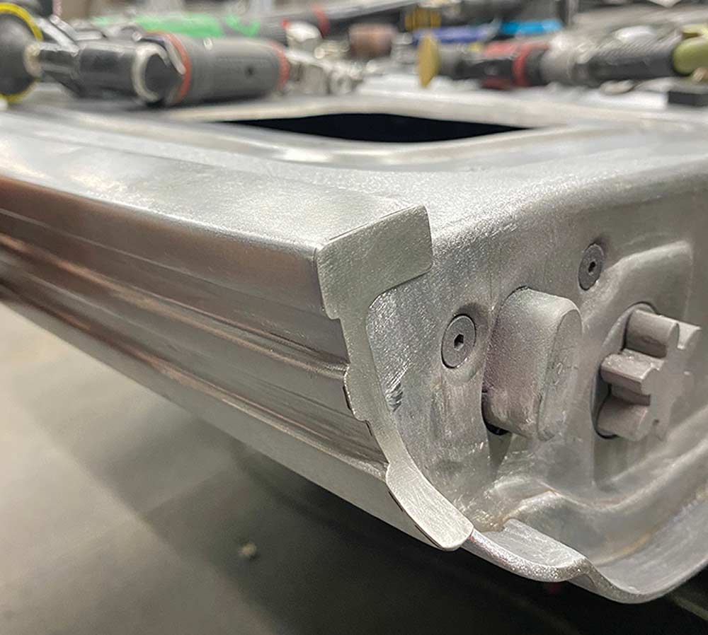
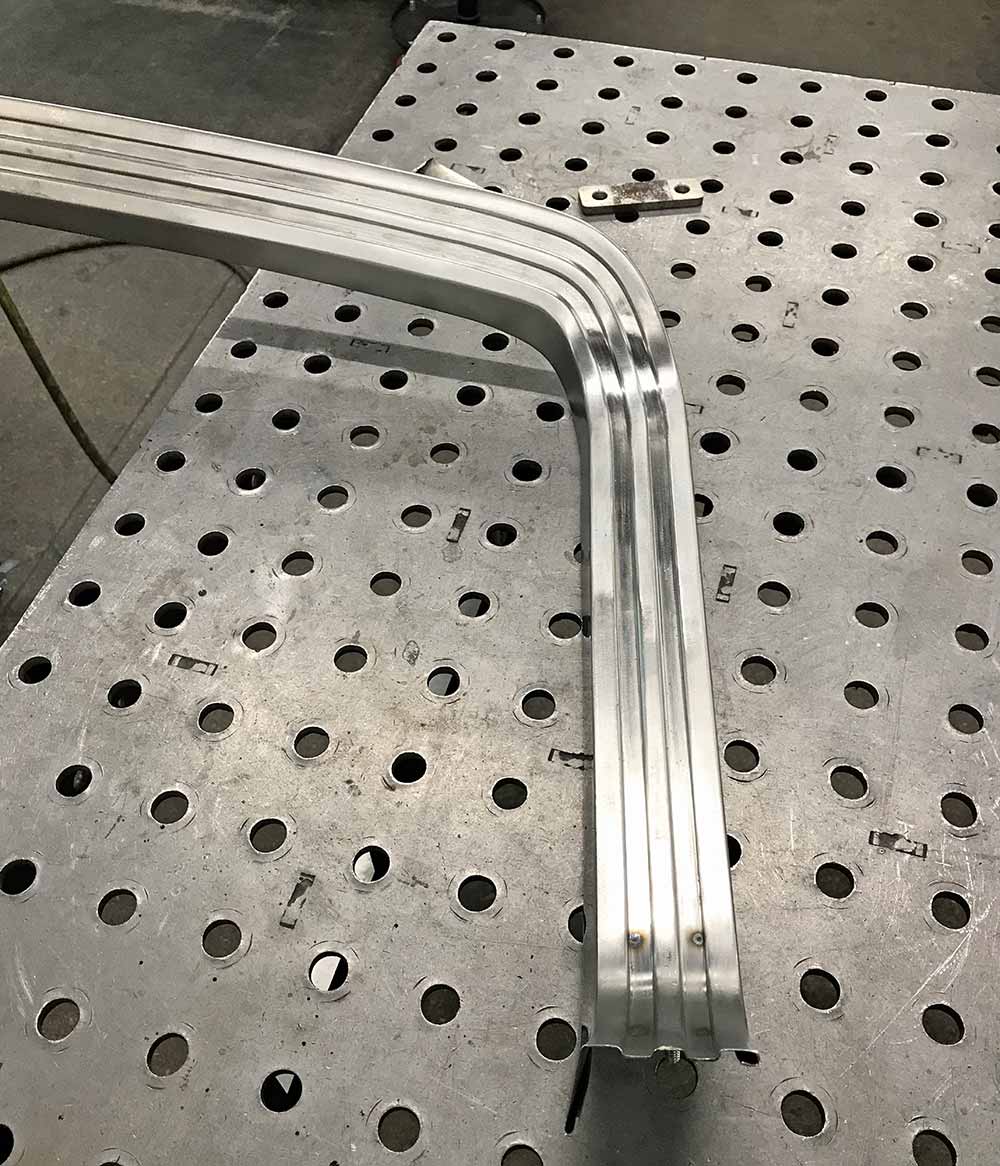
Detail of a new flanged end corner-welded onto the stainless trim.
10. The ends of the modified stainless trim were trimmed and then extended or shortened as needed. New flanged ends were cut and formed to fit. The flanges were corner welded and metal finished.
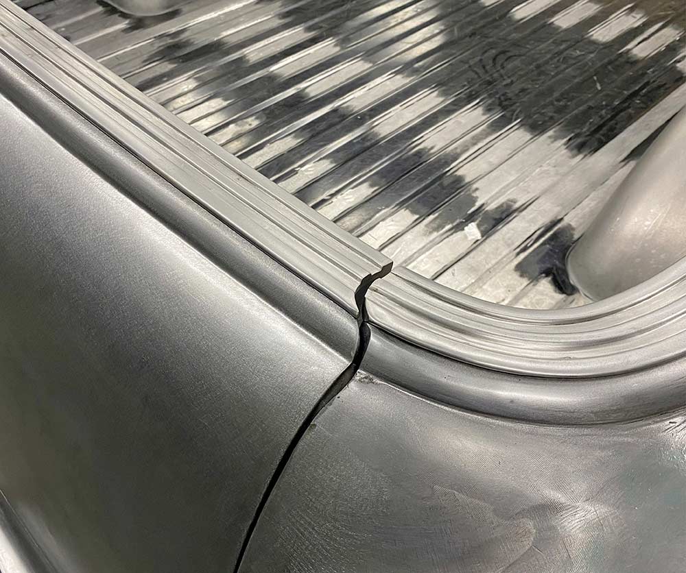
Fitment gap between the cab trim and the adjacent bed trim.
11. Replacing the flanged edges allowed the gaps to be corrected and made consistent with the adjacent trim. Additional work was previously done to rework the top of the tailgate to improve the beltline detail running under the trim, resulting in a more consistent fit.
Recessed mounting pan fabricated for hidden trim fasteners.
12. Small pans were fabricated with new mounting holes. These recessed pans were placed around the perimeter of the trim at appropriate locations with backside access to install a washer and a nylon nut.
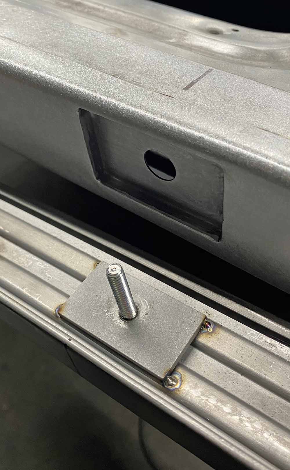
Threaded stud plate used for secure, wave-free trim installation.
13. These large threaded stud plates help distribute the drawing force when tightening the nylon nut fasteners. This design reduces the draw to prevent low spots or waves in the finished trim.
Clean, smooth look of the passenger side bed trim with hidden fasteners.
14. Completed hidden fasteners installed on the passenger’s side bed trim achieve a modern, smooth look. Removing the unnecessary seams and holes also improves the original fitment and allows the gaps to be dialed in.
Hand-formed corner trim piece being test-fitted on the body.
15. The corners were originally stamped from thin sheet metal. We initially tried to rework them, however, we reached a point where we realized it would be easier to make them from scratch. Doing so would also yield better results in terms of how they fit.
Milling a set of male and female dies from mild steel.
16. The profile was measured, and a set of male and female dies was machined from mild steel on the Bridgeport vertical mill. Proper tolerances were specified for the 18-gauge stainless steel sheet metal thickness, particularly in the vertical sections of the steps.
Machined steel die with clearance radii for turning corners.
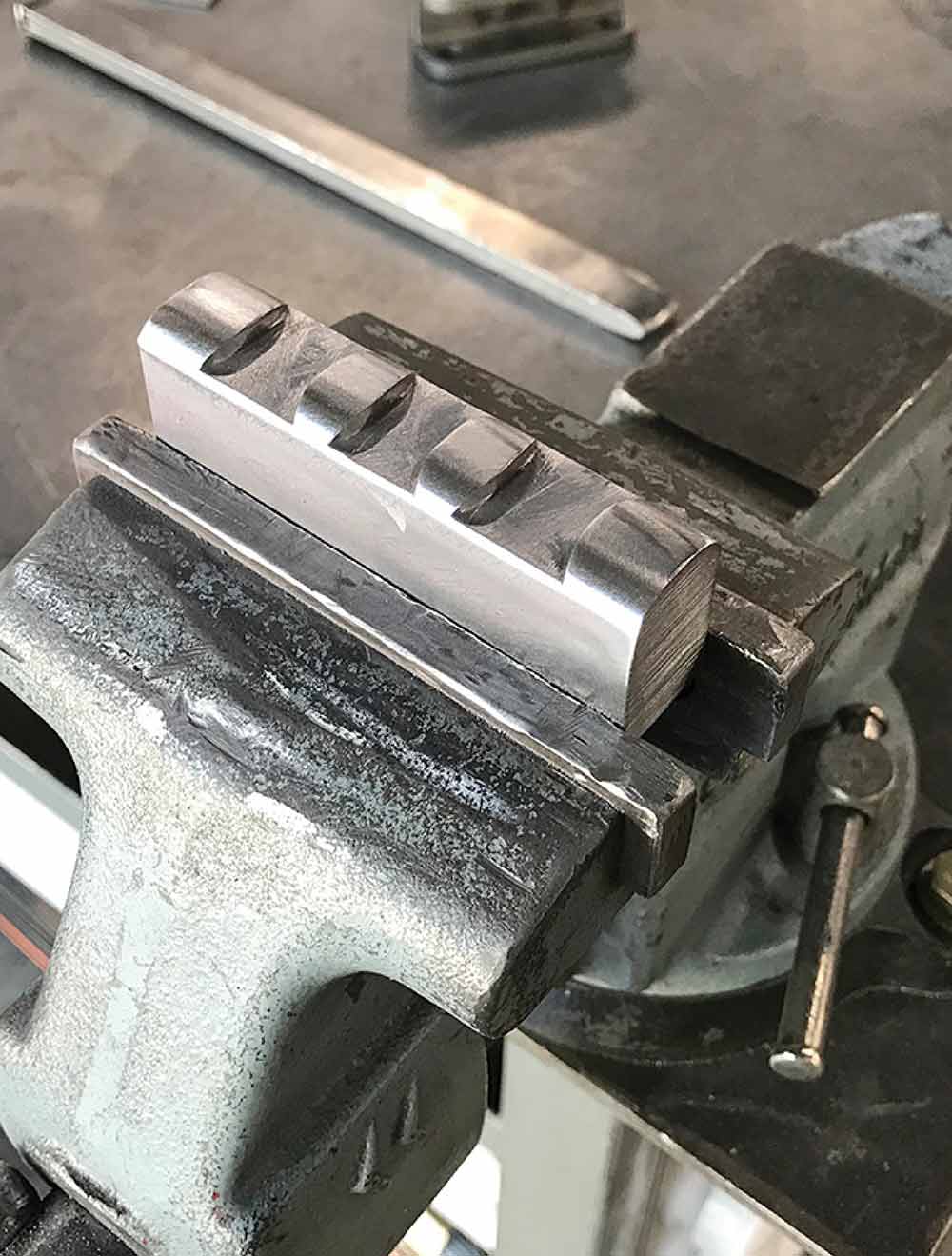
17. Clearance radii are needed on the outside corners and die face to turn corners, minimizing gouges on the sheet metal’s surface finish. Hand files were used to develop the necessary details while the die was held in a vise.
Sheet metal templates and tools used for creating the corner trim.
18. Templates were created for the contours needed at the left and right corners. Additional material was added to the edges for the flanges. The ERCO Former was used to brake 5/16-inch-tall, 90-degree flanges on the inside and outside edges of the stainless steel sheet metal blanks.
Forming bead details in the stainless trim using a Pullmax machine.
19. Two holes were drilled through the sides of the custom dies to bolt them into the universal P9 Pullmax die holders. The flanged edges served as guides to locate the trim while forming the multiple joggle (step) bead details.
Forming a 180-degree U-flange edge with a hammer and dolly.
20. A simple forming dolly was fabricated from scrap mild steel. A hammer and dolly were used to slowly form the outside edges into a 180-degree U-flange. Basic hand-forming methods are often the most efficient for small one-off parts.
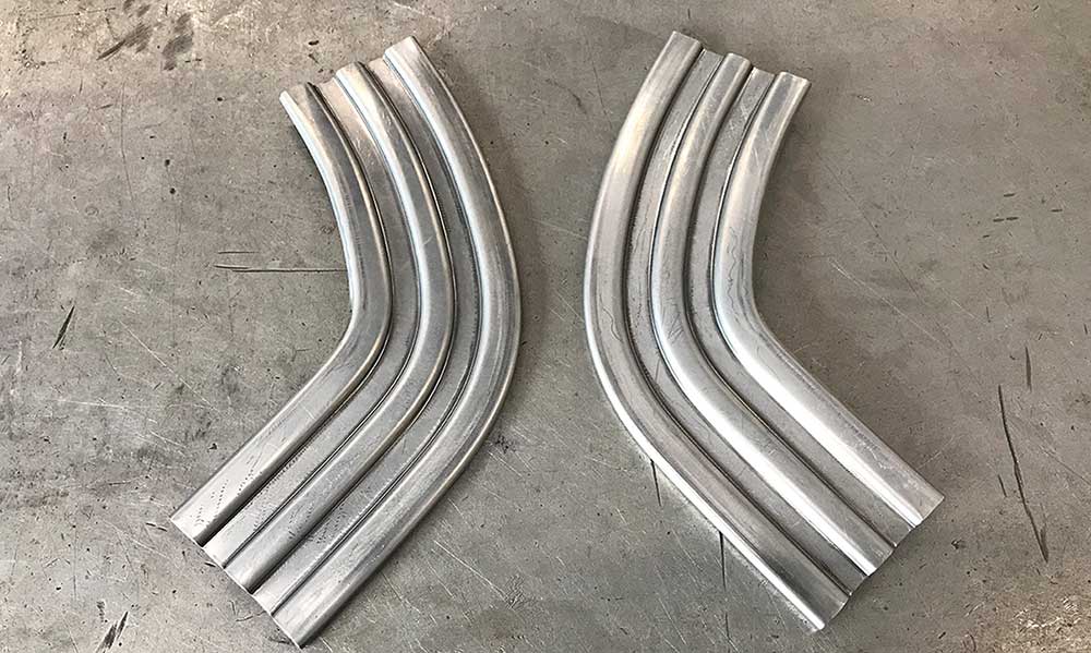
A pair of completed custom-formed stainless corner trim pieces.
21. After the forming process, the completed trim pieces are produced. Multiple passes through the Pullmax are made with a short-stroke setting to reduce die engagement per pass. This process results in smooth parts with little to no tooling marks from stamping.
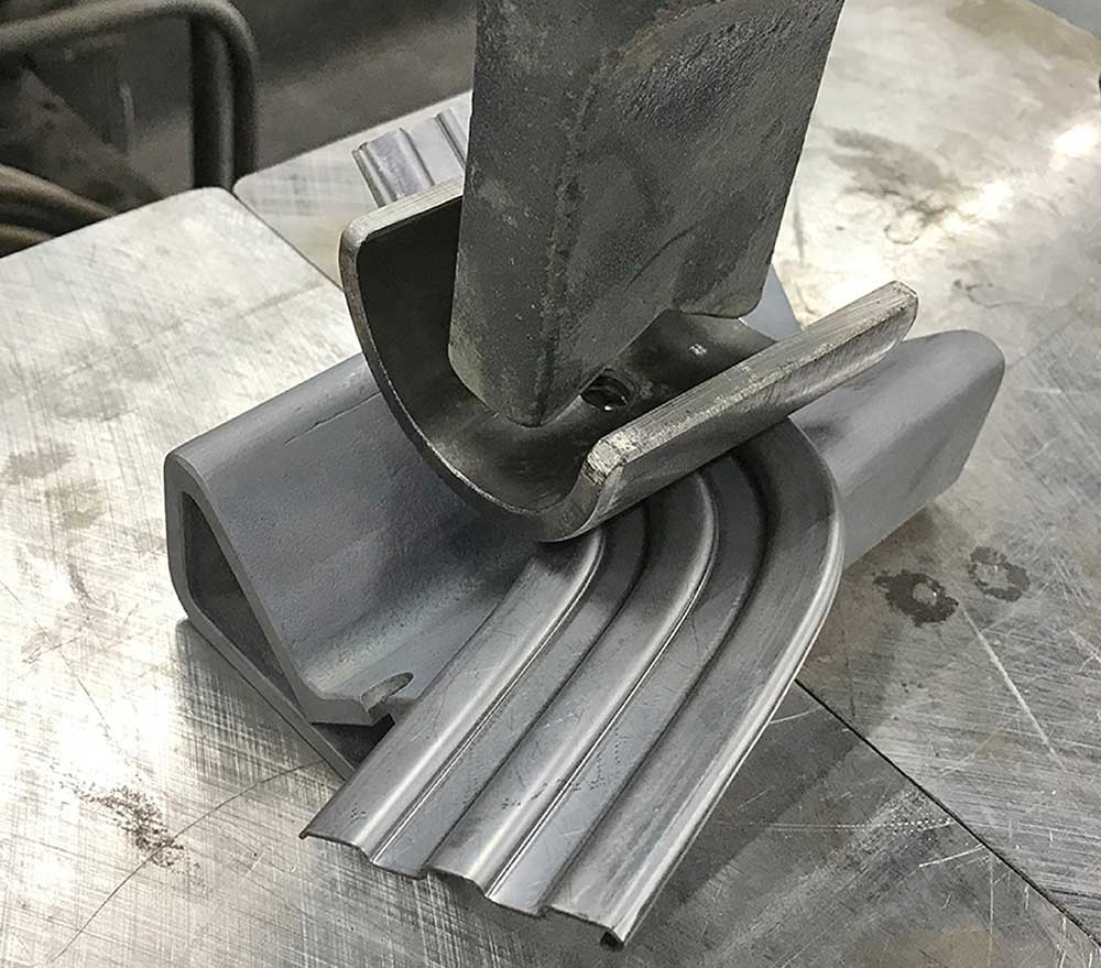
Creating the corner radius using a hydraulic shop press and forming tool.
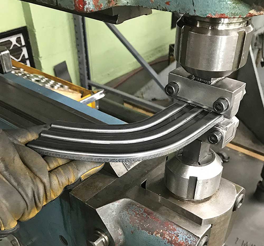
22. A simple forming tool in the hydraulic shop press was used to form the corner radius. A thick-walled piece of tubing on top and a fabricated V-block on the bottom, made from scrap angle iron, worked well for making multiple small, precise movements to avoid kinking the trim while it was being formed.
Tack-welding the formed stainless trim around the rear window frame.
23. The formed trim was cut to fit the surrounding trim pieces. It was tack welded at the corners with the TIG welder while in position. The majority of it was finally welded on the car before being removed for final finishing on the workbench.
Individually formed inside corner flanges ready for final assembly.
24. The inside corner flanges were formed separately and then welded in.
Aligning the bead details on the corner trim segments for welding.
25. Micro-adjustments were made to the edges to line up each section of the bead detail correctly before final welding.
Detail of the corner seams after picking and sanding for a seamless look.
26. The corners are painstakingly picked and sanded with small sanding blocks and files until the seams disappear. The goal was to make the modified stainless trim look as if it were stamped from a single sheet of stainless steel.
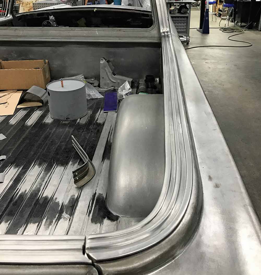
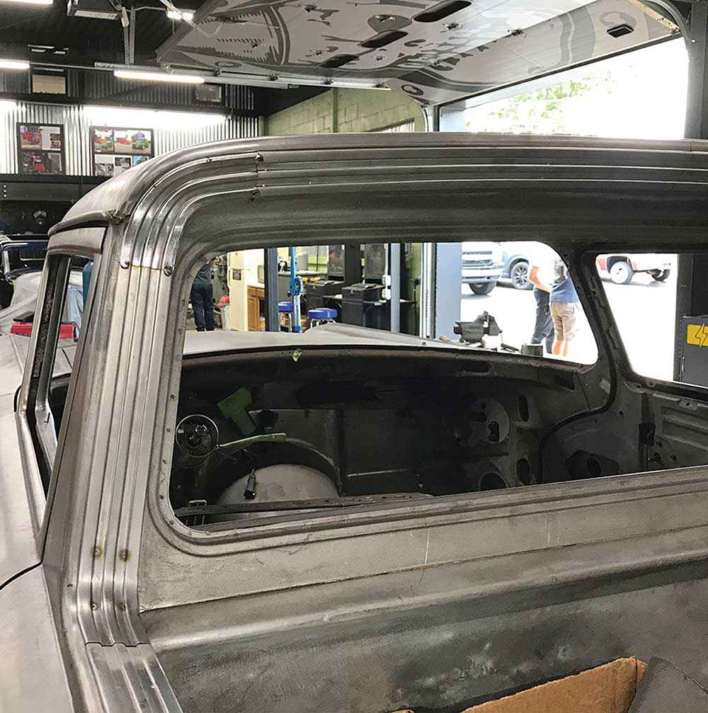
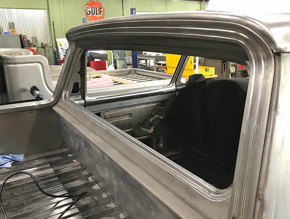
View of the finished stainless trim around the rear Ranchero window.
27. Completed trim around the back window. A total of six seams were eliminated, leaving only two necessary seams for an all-new contemporary look that preserves the original vibe.
In The Garage Media
TIN MAN’S GARAGE

Modern Rodding
VOLUME 7 • ISSUE 71 • 2026