Modern Rodding TECH

InTheGarageMedia.com

36 Ford Roadster illustration
1. The Adam Banks artwork gives a good representation of what the outcome is going to look like.
’36 Ford Roadster
Part 4: Y-Block Power, McCulloch Supercharger, and Suspension
By Ron Covell Photography by Adam Banks
A

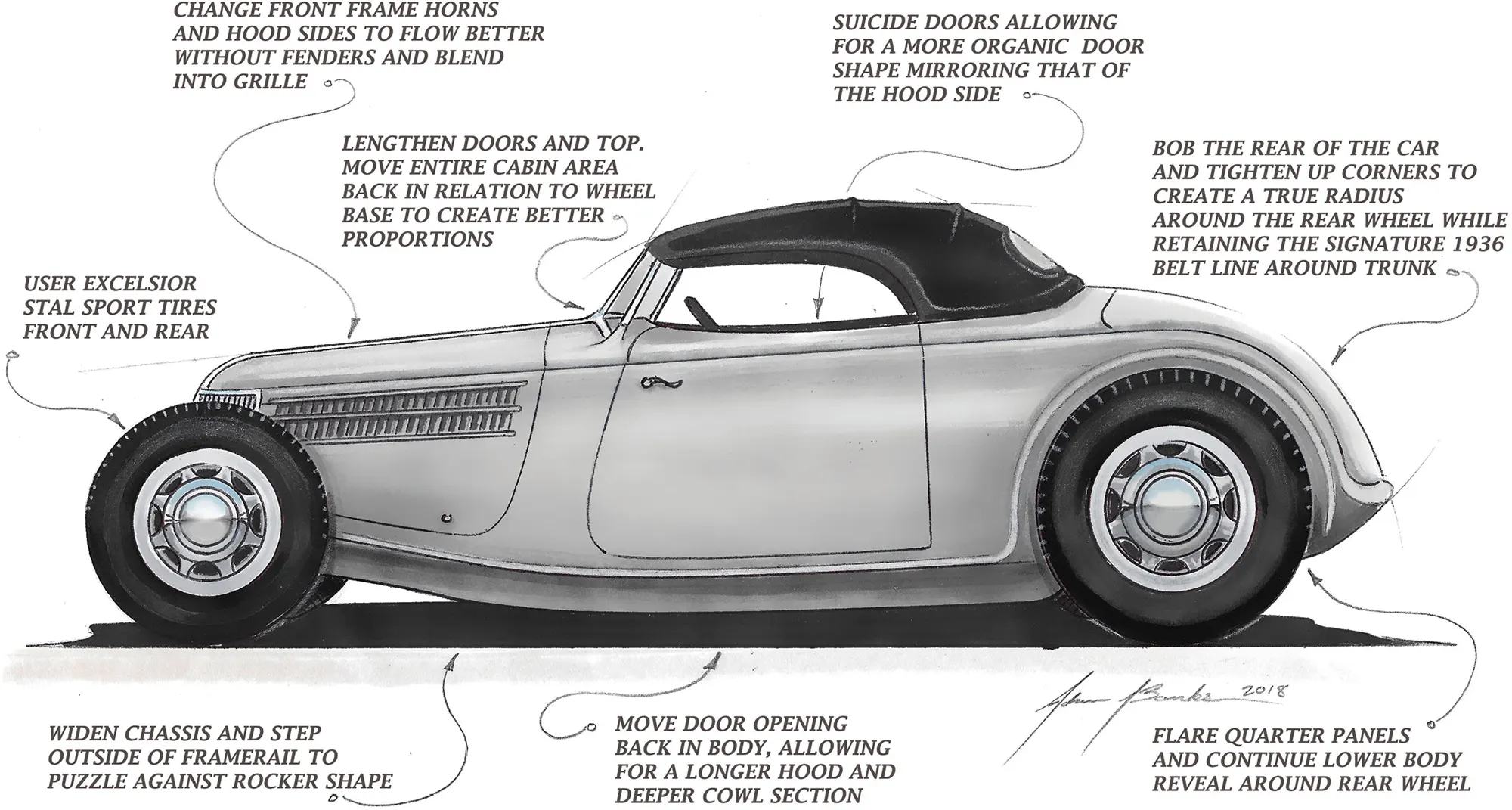
tremendous amount of work goes into building a car from the ground up. In past installments we followed the Rad Rides by Troy team through the construction of the frame and major body components for this fenderless ’36 Ford roadster being built for Ross Myers. With those components largely completed, it was time to fit the engine and drivetrain and to design and fabricate the suspension system.

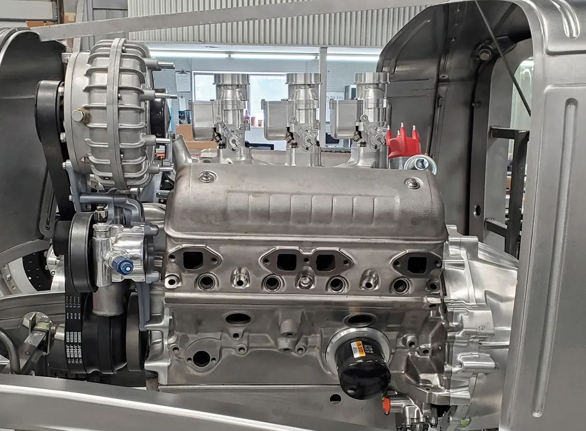
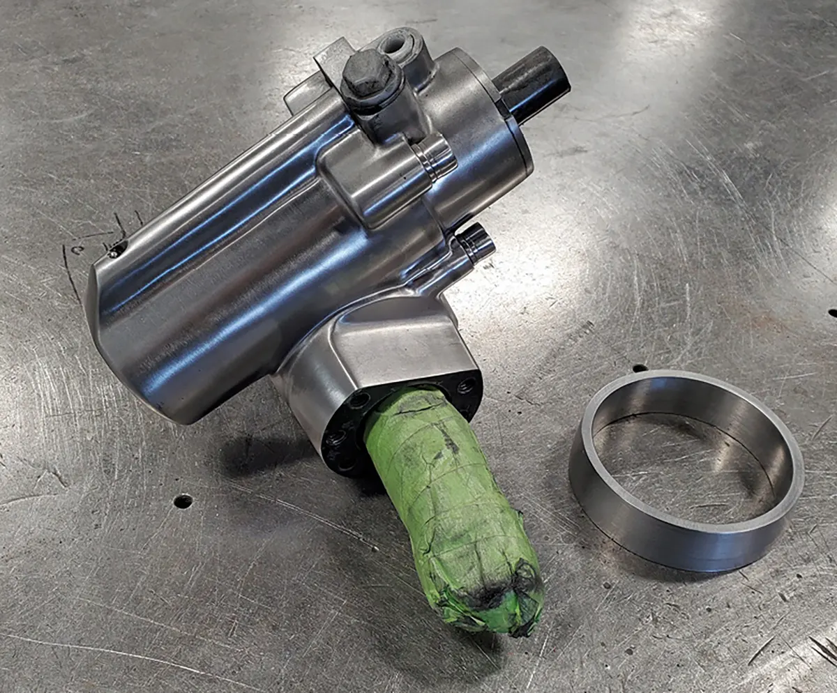
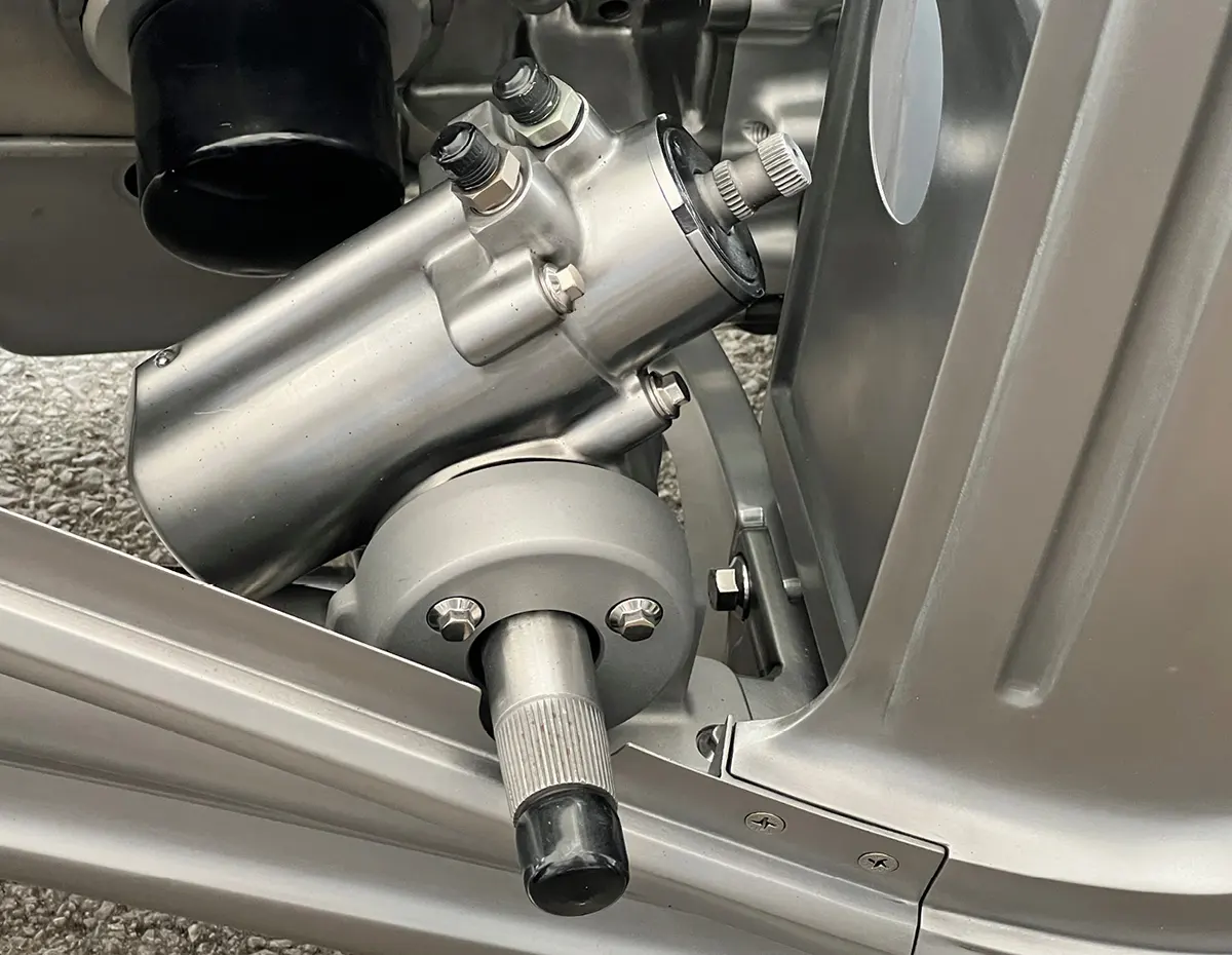
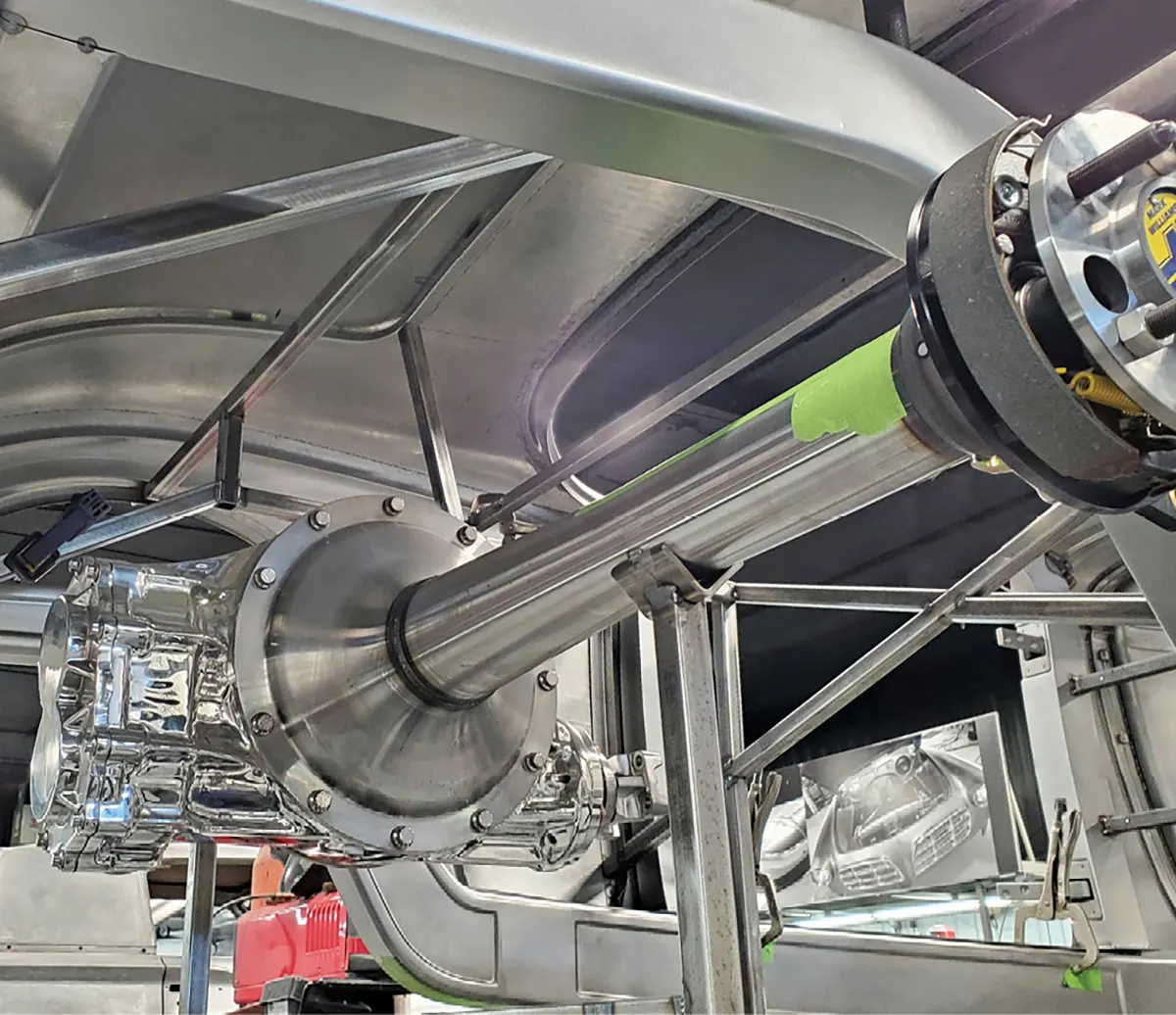
A Ford Y-block engine was selected and fitted with vintage-looking components that were cleverly updated to provide the functionality of a modern car. A McCulloch VS57 supercharger was used, but Pat Fleischman from Lubbock, Texas, was called on to equip it with the internal components from a Paxton supercharger. The engine will have fuel injection but the Autotrend EFI throttle bodies look very much like vintage Stromberg carburetors. Rad Rides has a reputation for building cars that perform at the highest level, but on a car like this, maintaining a vintage look is part of the discipline.

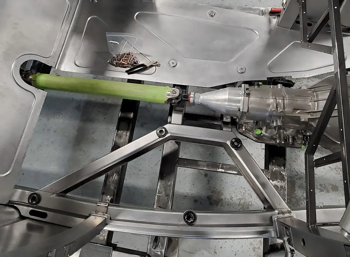
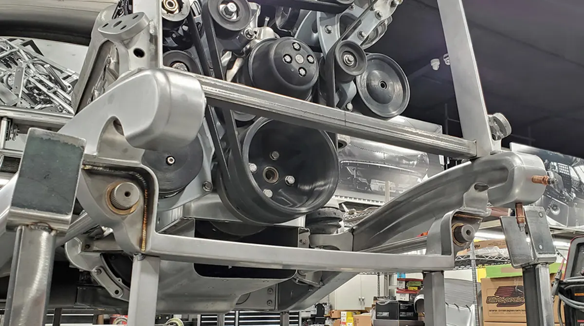
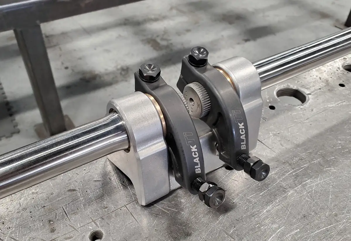
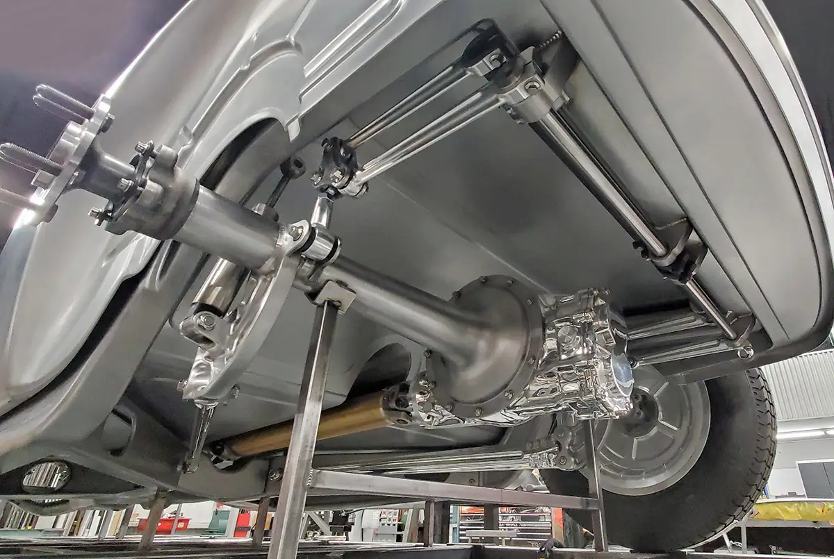
Torsion bars were used on both ends of the car, longitudinal in the front and transverse in the rear. A lot of thought went into positioning the suspension components so they tuck neatly into the chassis, providing an exceptionally clean appearance and leaving as much open space as possible. On an open-wheeled car like this, these details can make a huge difference.

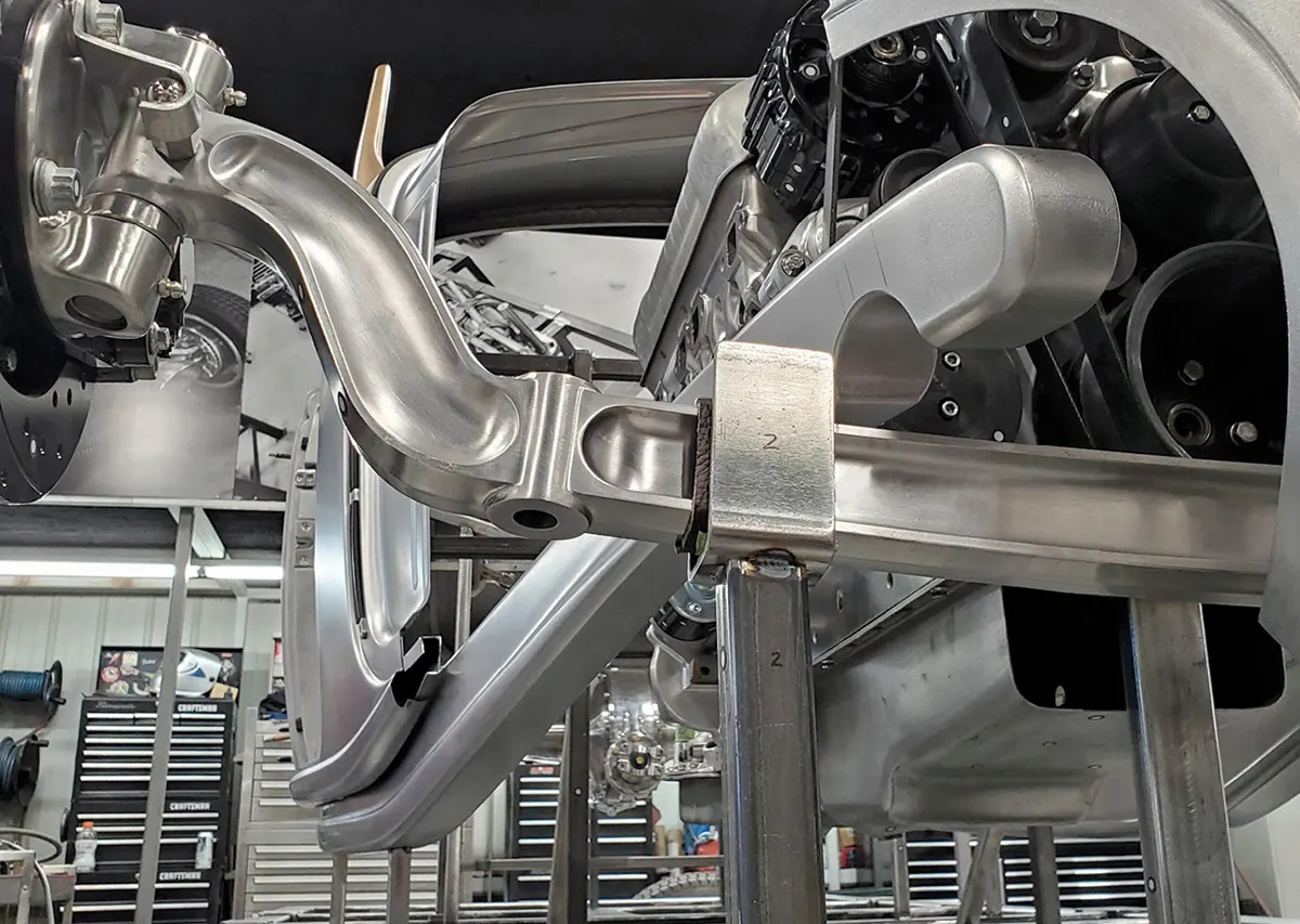
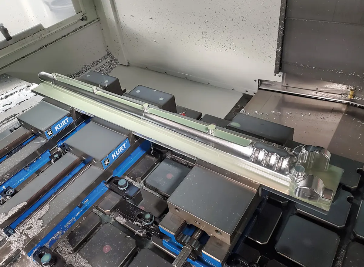
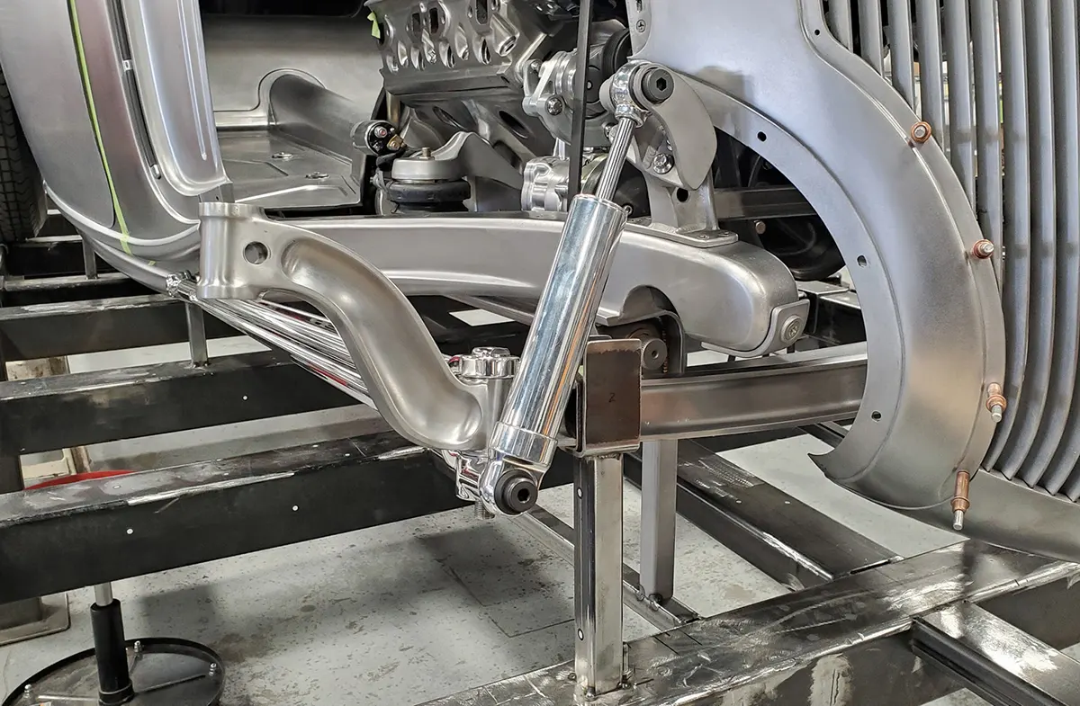
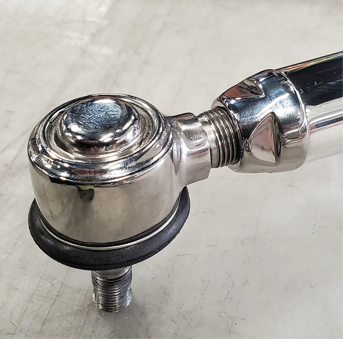
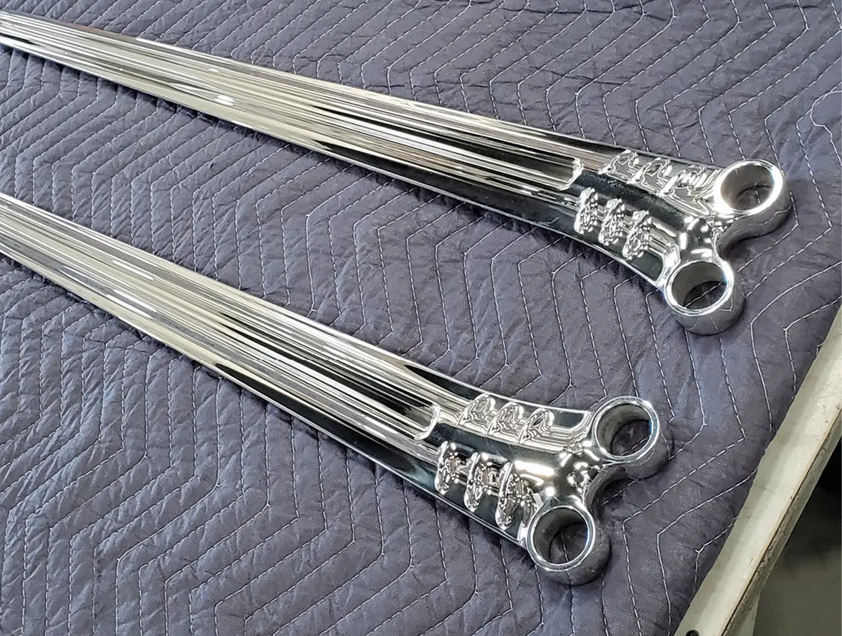
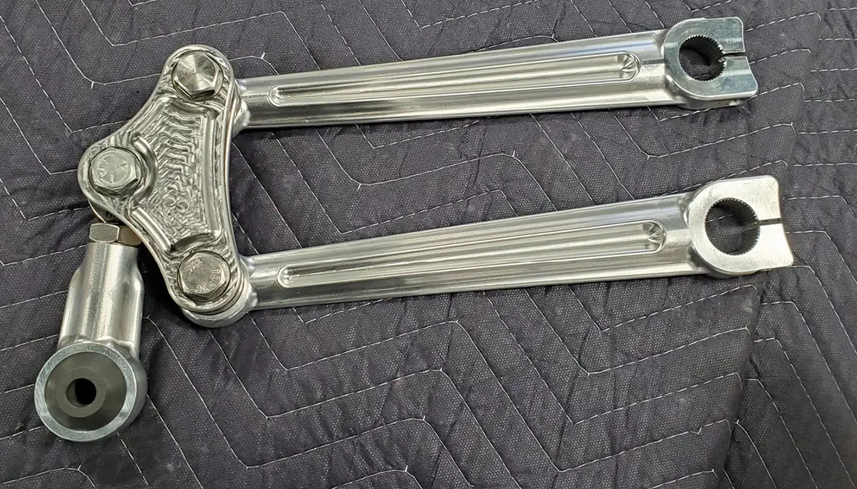
Special radius rods were machined for the front and rear axles. These are highly detailed components, incorporating a ribbed design element. A great deal of planning went into making them blend visually with the other components while retaining the vintage look of a straight-axle car.

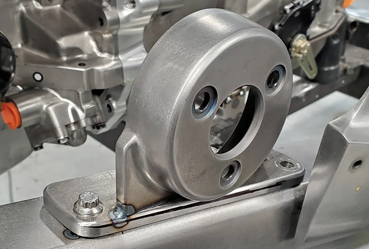
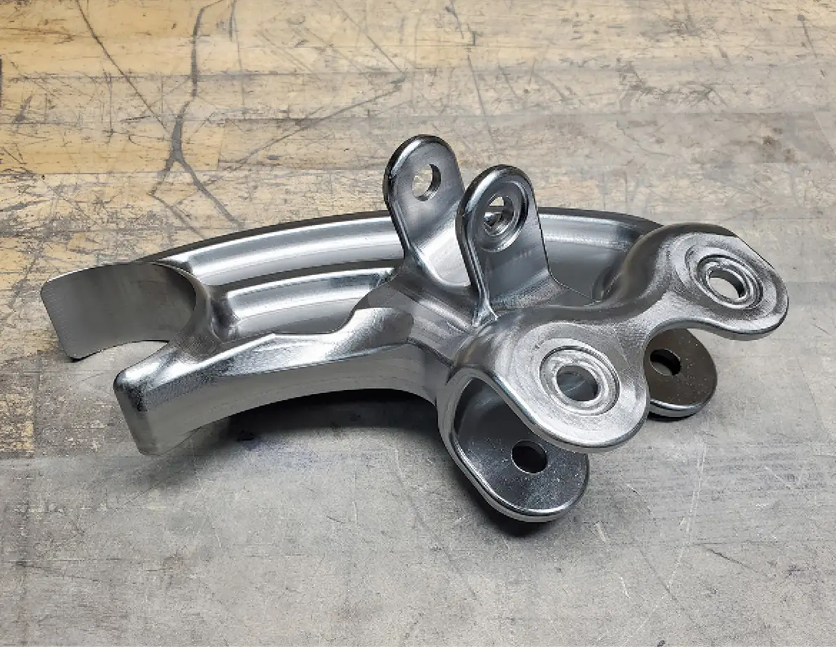
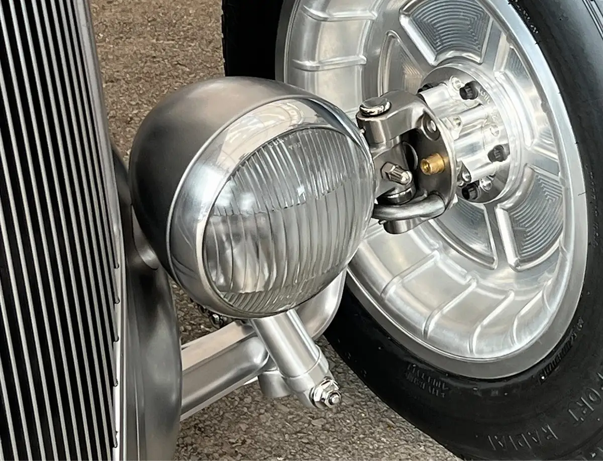
Special shock mounts were made for both axles. In front where they are more visible, the Rad Rides team found a way to hide the top half of the shock inside the headlight. This required some rather complex fabrication and machining, allowing the highly loaded components to be easily assembled and disassembled, but the results are well worth the extra effort.

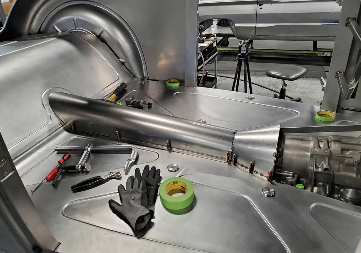
If you are enjoying this series, look for the next episode where the fabrication and fitting of some of the more complex sheetmetal components will be covered.

Banks is working on trim for the custom grille shell, which is but one of many custom, hand-fabricated pieces on this outstanding ’36 Ford roadster.
2. Banks is working on trim for the custom grille shell, which is but one of many custom, hand-fabricated pieces on this outstanding ’36 Ford roadster.
The engine for the roadster is a Ford Y-block, fitted with a rare McCulloch VS57 supercharger updated with Paxton internals and throttle bodies from Autotrend EFI.
3. The engine for the roadster is a Ford Y-block, fitted with a rare McCulloch VS57 supercharger updated with Paxton internals and throttle bodies from Autotrend EFI.
A Rad Rides–made adapter plate connects the engine to the 4R70W transmission. The power is then transferred to the Winters Champion quick-change rearend through a custom-made driveshaft.
4. A Rad Rides–made adapter plate connects the engine to the 4R70W transmission. The power is then transferred to the Winters Champion quick-change rearend through a custom-made driveshaft.
After the driveshaft was fitted, a low-profile cover was made from 18-gauge steel.
5. After the driveshaft was fitted, a low-profile cover was made from 18-gauge steel.
A Classic Performance Products power steering unit was painstakingly smoothed. The steel ring on the right will become part of the mount that holds the unit to the chassis.
6. A Classic Performance Products power steering unit was painstakingly smoothed. The steel ring on the right will become part of the mount that holds the unit to the chassis.
Here’s the steering mount under construction. All the welds are blended so the part looks like a steel forging.
7. Here’s the steering mount under construction. All the welds are blended so the part looks like a steel forging.
With the steering box attached to the chassis, the assembly looks as if it was factory designed.
8. With the steering box attached to the chassis, the assembly looks as if it was factory designed.
Torsion bars are used for the front suspension. Here you can see the mounts for the bars carefully positioned below the framerails, so they will be largely hidden when the car is on the ground.
9. Torsion bars are used for the front suspension. Here you can see the mounts for the bars carefully positioned below the framerails, so they will be largely hidden when the car is on the ground.
Here’s the front axle, positioned at normal ride height. The forged front axle has been hand-detailed to give it a crisp, smooth finish, looking like it was machined from billet.
10. Here’s the front axle, positioned at normal ride height. The forged front axle has been hand-detailed to give it a crisp, smooth finish, looking like it was machined from billet.
The front radius rods were CNC machined from aluminum billet. They feature a ribbed theme near the front attachment that will be mimicked on the rear radius rods.
11. The front radius rods were CNC machined from aluminum billet. They feature a ribbed theme near the front attachment that will be mimicked on the rear radius rods.
This is how the radius rods attach to the front axle; you can see the shackle used to connect the torsion arms.
12. This is how the radius rods attach to the front axle; you can see the shackle used to connect the torsion arms.
A special front crossmember was added just in front of the axle, with a vertical slot that engages a shaft extending through a bushing in the axle. This allows all the parts to articulate while keeping the axle centered and it eliminates the need for a Panhard bar.
13. A special front crossmember was added just in front of the axle, with a vertical slot that engages a shaft extending through a bushing in the axle. This allows all the parts to articulate while keeping the axle centered and it eliminates the need for a Panhard bar.
Special mounts were made for the front shocks, designed so the upper portion is hidden inside the headlight shell. This provides a superclean appearance at the front of the car.
14. Special mounts were made for the front shocks, designed so the upper portion is hidden inside the headlight shell. This provides a superclean appearance at the front of the car.
From the side, you can see how beautifully all the components fit together, with nothing looking tacked on or out of place.
15. From the side, you can see how beautifully all the components fit together, with nothing looking tacked on or out of place.
Special jam nuts were made to lock the rod ends into place at the ends of the radius rods. You’ll find countless little details like this throughout the build.
16. Special jam nuts were made to lock the rod ends into place at the ends of the radius rods. You’ll find countless little details like this throughout the build.
A Winters Champion quick-change rearend was selected. It is positioned here at normal ride height to start the layout of the suspension system.
17. A Winters Champion quick-change rearend was selected. It is positioned here at normal ride height to start the layout of the suspension system.
Unique radius rods were CNC machined from aluminum billet and polished to a mirror finish.
18. Unique radius rods were CNC machined from aluminum billet and polished to a mirror finish.
A very complex bracket was CAD-designed and CNC machined from steel to mount the rear radius rods and shocks to the rear axle housing.
19. A very complex bracket was CAD-designed and CNC machined from steel to mount the rear radius rods and shocks to the rear axle housing.
Here the bracket is welded to the rear axle tubes and the components are attached.
20. Here the bracket is welded to the rear axle tubes and the components are attached.
Transverse torsion bars are used at the rear. Each bar terminates at the adjusters for ride height, located at the center of the chassis.
21. Transverse torsion bars are used at the rear. Each bar terminates at the adjusters for ride height, located at the center of the chassis.
This closeup shows the details of the height adjusters and the inner torsion bar mounting block. The torsion bars rotate in bronze bushings at both ends.
22. This closeup shows the details of the height adjusters and the inner torsion bar mounting block. The torsion bars rotate in bronze bushings at both ends.
A unique, low-profile linkage system was used so the torsion bars and antiroll bar could be positioned high in the chassis, reducing visual clutter and leaving lots of room for routing the exhaust system.
23. A unique, low-profile linkage system was used so the torsion bars and antiroll bar could be positioned high in the chassis, reducing visual clutter and leaving lots of room for routing the exhaust system.
Here you can see how neatly all the suspension elements tuck up underneath the body.
24. Here you can see how neatly all the suspension elements tuck up underneath the body.
Using torsion bars instead of a leaf spring and hiding the top of the shock absorber inside the headlight gives the front of the car a very clean appearance. Custom billet wheels were specially made for this car.
25. Using torsion bars instead of a leaf spring and hiding the top of the shock absorber inside the headlight gives the front of the car a very clean appearance. Custom billet wheels were specially made for this car.
The wheels pay tribute to the wide-five pattern used on the original Ford wheels from 1936.
26. The wheels pay tribute to the wide-five pattern used on the original Ford wheels from 1936.
SOURCE
Modern Rodding
VOLUME 5 • ISSUE 43 • 2024