Modern Rodding TECH
InTheGarageMedia.com

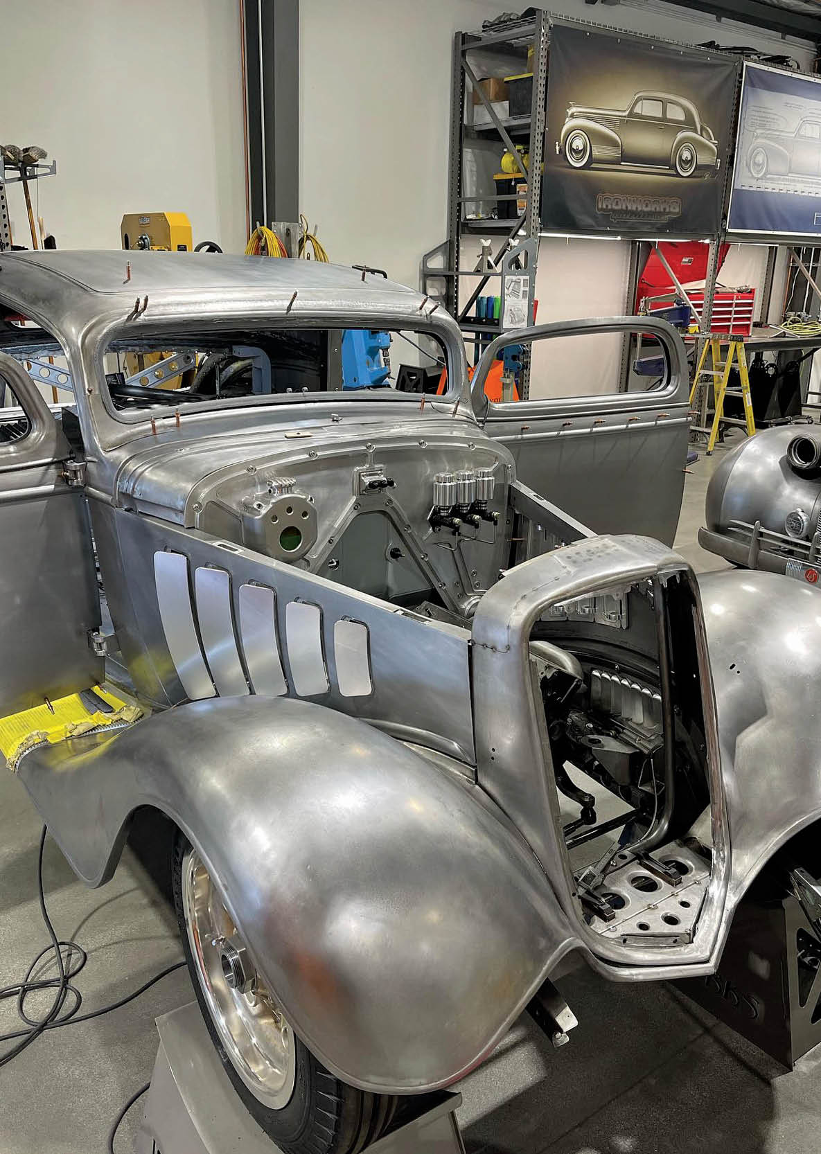
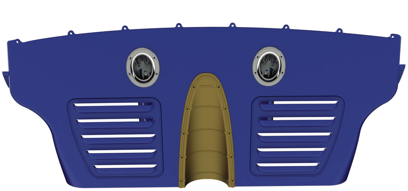
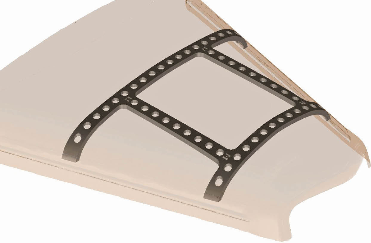
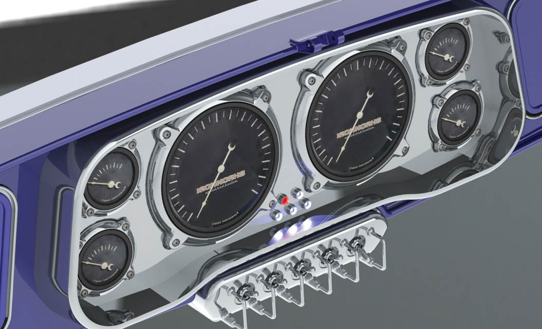
1. The finished look is getting closer to reality. Thanks to Eric Black of e. Black Design we have a good idea of what our finished goal will look like.

The Devil is in the Detail title
Part 3: The Ultimate ’35 Chevy Coupe

By Ron Covell
Photography By Ron Covell & Rodger Lee
Videography By Rodger Lee
Artwork By e.Black Design

A

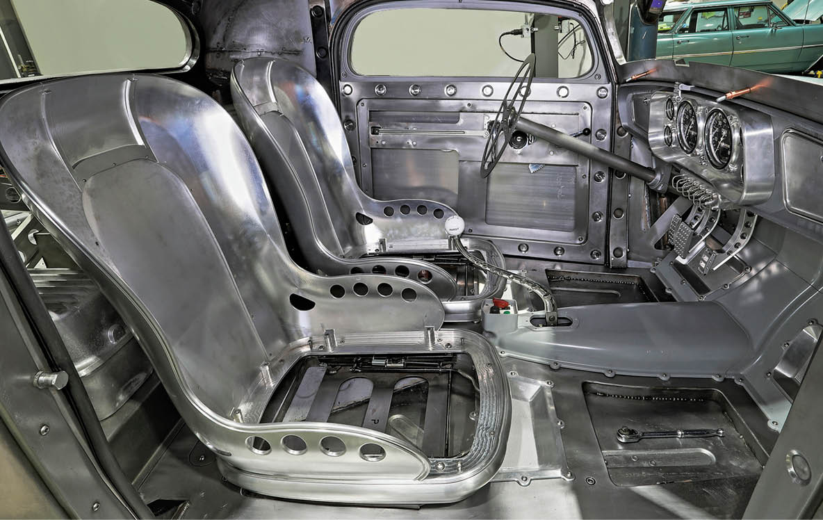
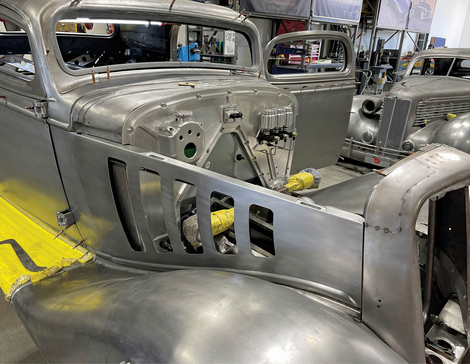
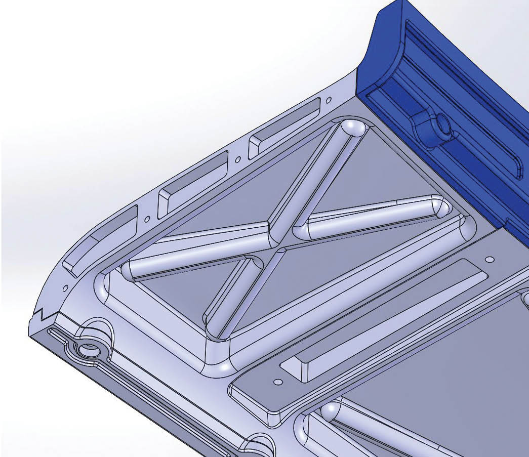
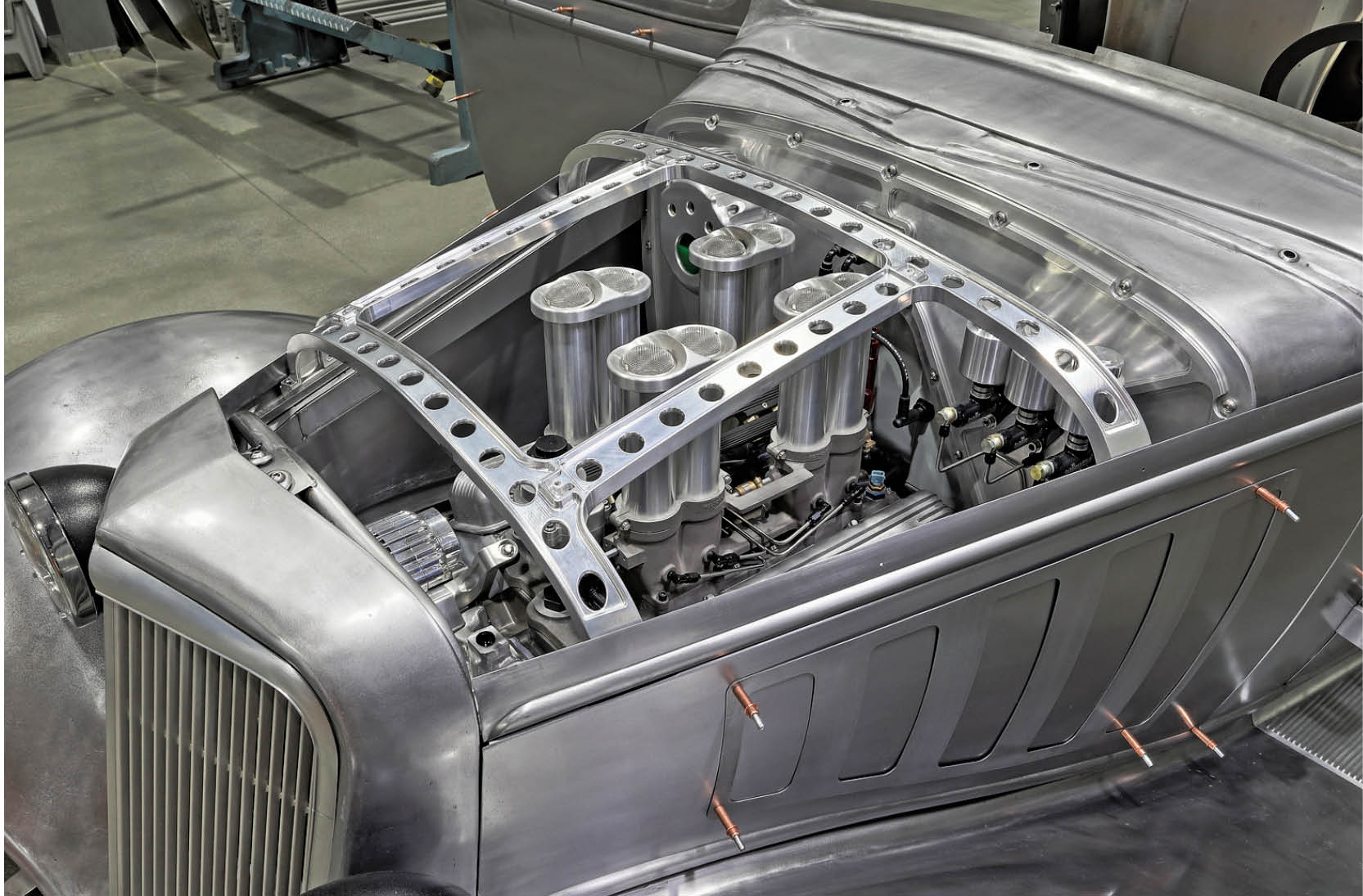
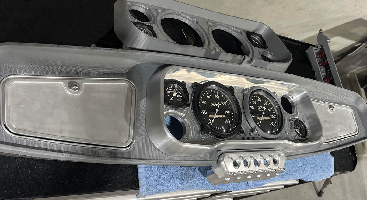
s work nears completion on Greg Heinrich’s cutting-edge ’35 Chevrolet coupe, we wanted to show how some of the outstanding details were handled. (In previous months, Modern Rodding has brought you chassis and sheetmetal work.) Ironworks Speed & Kustom has made a commitment to use the latest technology to design and build these parts. In most cases, the portion of the car where the parts will fit is scanned, so when the parts are designed in CAD they will fit precisely. Once the CAD model is completed, a plastic part is printed and then this part is checked for fit and appearance before machining the final part from billet aluminum. Opportunities for improvement often become apparent after the printed part is made, and frequently parts go through several revisions before the design is finalized.

Innumerable details were fabricated using this procedure, and the combined effect is stunning. Our photos show the bucket seats, articulated hood vent doors, running boards and their mounting brackets, the rear underbody valence panel, the hood top bracing, front inner fender panel, and the dashboard, but this is just the tip of the iceberg. Some other components made in this way are the firewall, transmission tunnel, bellhousing cover and toeboards, the pedal assembly, the hinged windshield frame, and the inner bezels for all the windows. We could go on, but you get the idea that no expense was spared to bring the styling, fit, and finish on this car to an extreme level.

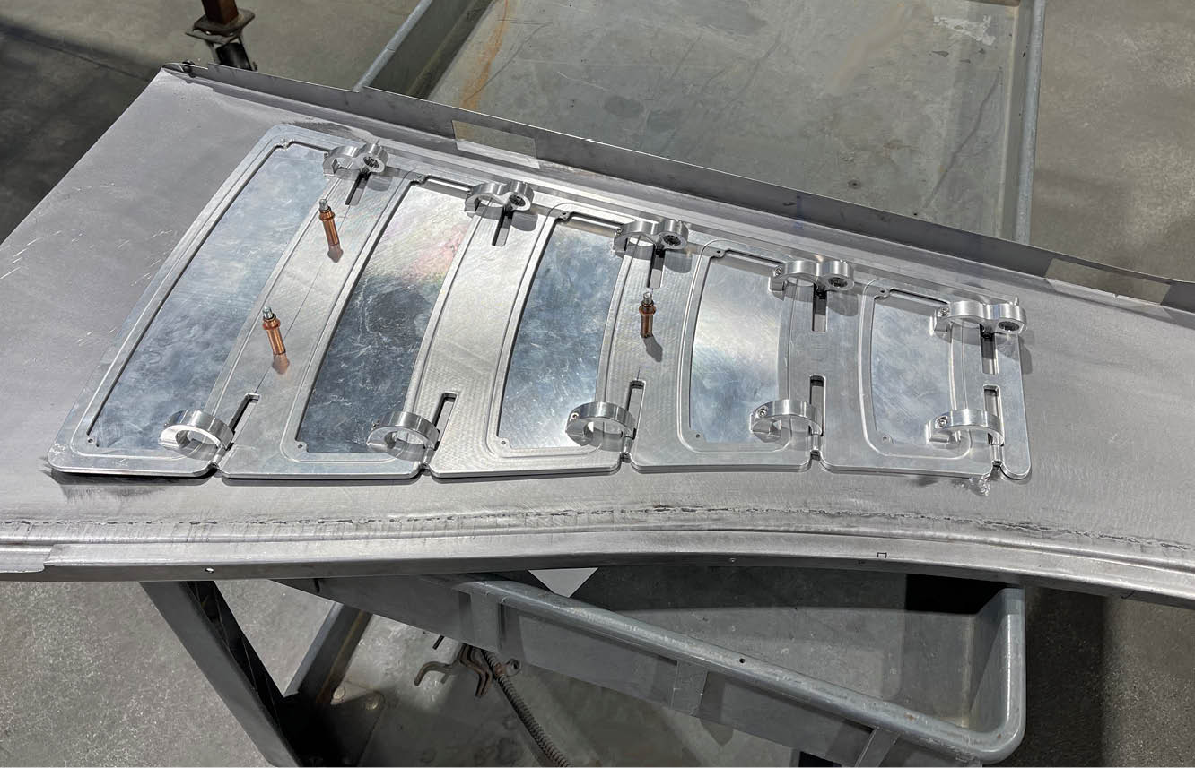
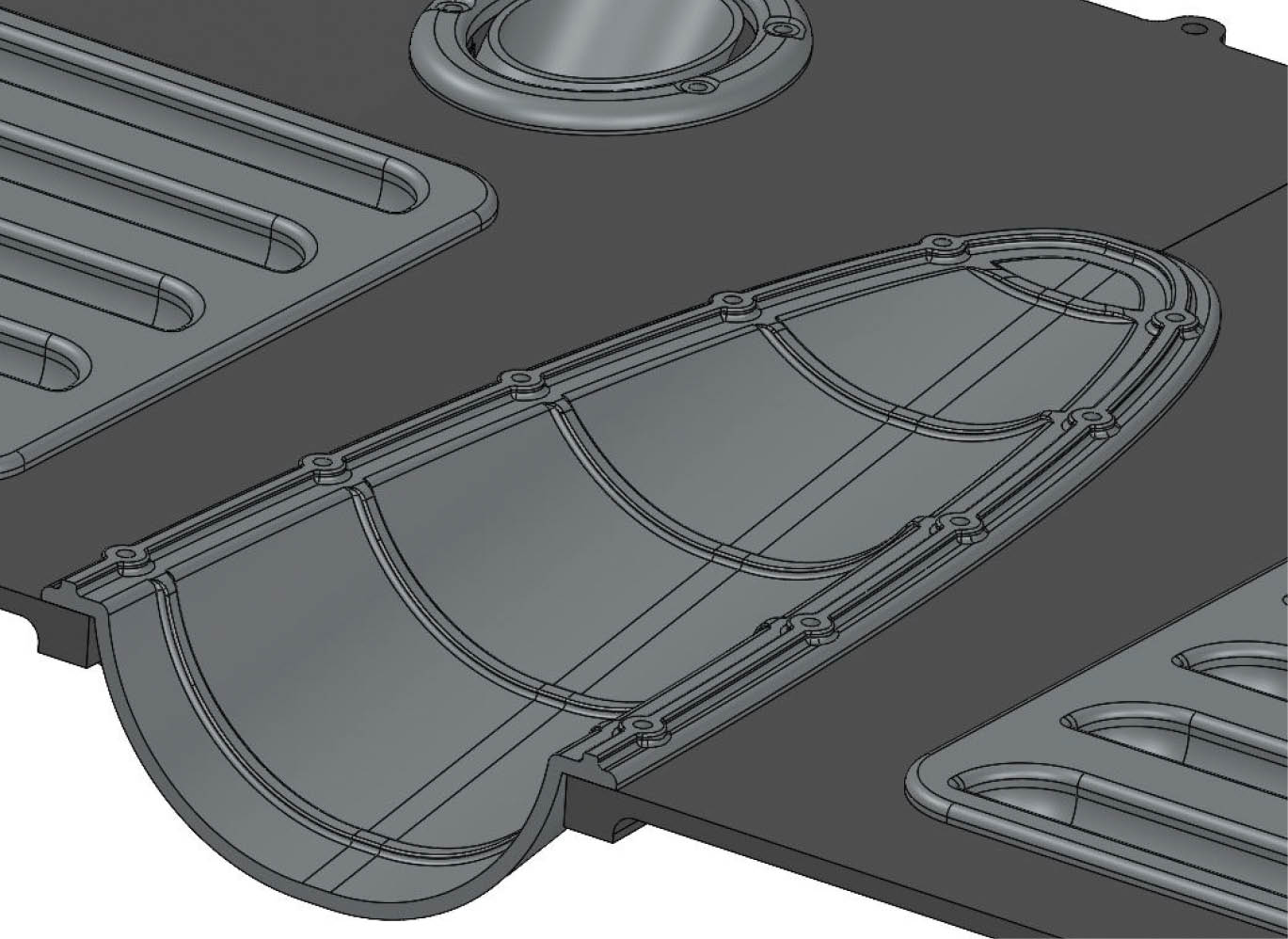
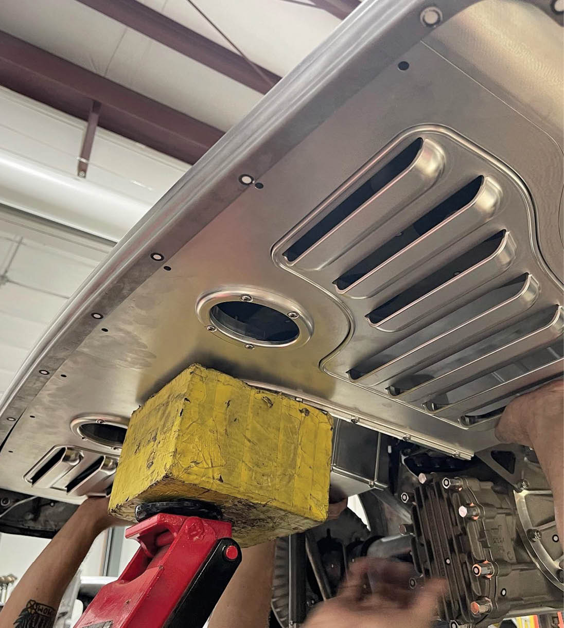
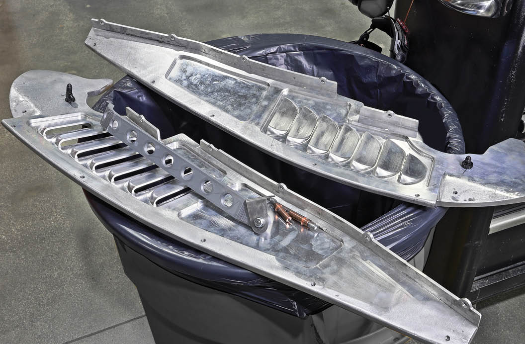
Manufacturing parts in this way brings a new level of precision to the building process, and when you look at the deeply sculped louvers on the front inner fender panels and the rear valence panel you can imagine how challenging it would be to fabricate these parts from sheetmetal. The process worked so well that many of the original Chevrolet parts were replaced by parts machined from billet, too.

Most of what you see in this photo was designed in CAD, checked by printing a plastic part, tweaked as needed, and then CNC machined from billet aluminum.
2. Most of what you see in this photo was designed in CAD, checked by printing a plastic part, tweaked as needed, and then CNC machined from billet aluminum.
In this close-up shot of the seat frame you can see the superb quality of finish achieved by precision machining.

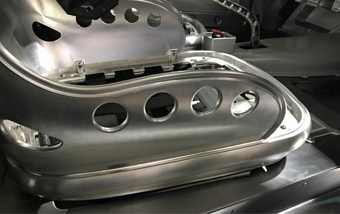
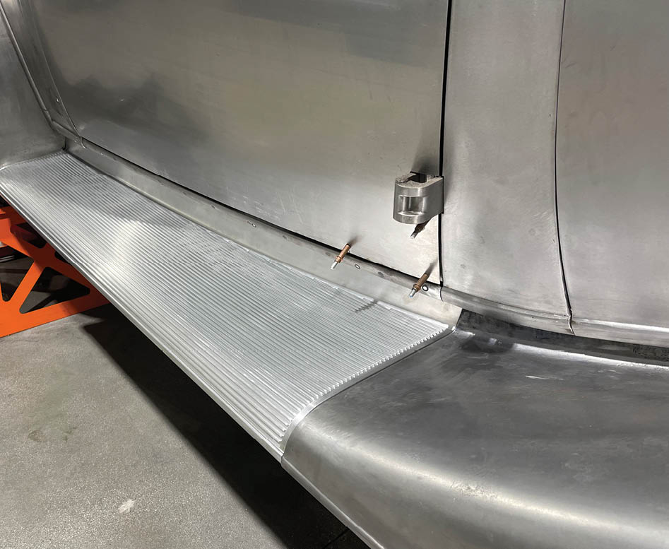
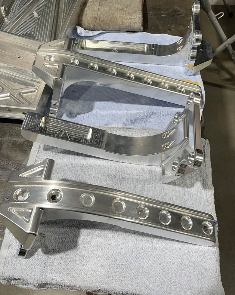
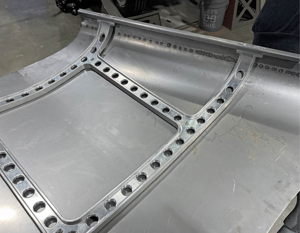
3. In this close-up shot of the seat frame you can see the superb quality of finish achieved by precision machining.

The inner portions of the seat frames will be covered with foam and upholstery, but even these hidden areas are beautifully finished.
4. The inner portions of the seat frames will be covered with foam and upholstery, but even these hidden areas are beautifully finished.
Webbing is placed under the foam cushion in the seat bottom for OEM-style comfort.
5. Webbing is placed under the foam cushion in the seat bottom for OEM-style comfort.
entire firewall machined from billet
6. The entire firewall is machined from billet. Notice the openings cut in the hood side, in preparation for fitting the precisely contoured vent doors.
hood vent door
7. The hood vent door assembly is shown here in preparation for being bonded to the steel hood side.
machined aluminum components following the contours of the hood side
8. Here you can see how perfectly the machined aluminum components follow the contours of the hood side and the intricacy of the hinges and brackets for the linkage that moves all the doors in unison.
completed hood side
9. Here’s the completed hood side with the vent doors in place.
beautiful running boards machined from billet aluminum
10. The beautiful running boards are machined from billet aluminum, too. Note how perfectly they follow the shape of the body and the fenders.
CAD drawing showing the individual components
11. This CAD drawing shows the individual components the running boards are constructed from.
underside of the running boards
12. The underside of the running boards is finished just as beautifully as the top.
brackets for the running boards
13. These are the brackets for the running boards, which mount them securely to the chassis.
a preliminary CAD drawing for the valance panel that fits under the tail of the body
14. This is a preliminary CAD drawing for the valance panel that fits under the tail of the body.
individual components of the valance panel fitted together
15. You can see here how the individual components of the valance panel are fitted together.
completed rear valence panel
16. This is the completed rear valence panel, resting upside down on a bench. Shapes this intricate would be extremely challenging to make from sheetmetal.
valence panel being fitted into place
17. The valence panel is being fitted into place here. As you can see, it will fit like a glove since the body was precisely scanned before the part was designed.
rough layout of the robust bracing for the hood top
18. This is the rough layout of the robust bracing for the hood top.
simplified rectangular cross sections of the brace
19. Here you can see how the simplified rectangular cross sections of the brace have been relieved, creating an elegant I-beam shape. This reduces the weight and gives it an outstanding appearance.
uniform gap between the brace and the hood top
20. Note the uniform gap between the brace and the hood top. The hood latches are integrated into the design, too.
printed plastic inner fender panel
21. A printed plastic inner fender panel is being checked for size and fitment. It’s always a good idea to do these checks before committing to machining a part from billet.
billet aluminum inner fender panels
22. These are the billet aluminum inner fender panels in preparation for being fitted to the car.
CAD rendering of the dash instrument cluster
23. Here’s a CAD rendering of the dash instrument cluster. Many versions of this were modeled before making the final decision.
checking the fit of all the components before it is machined
24. The instrument cluster, glovebox doors, and the switch panel are machined from billet aluminum, and the larger dash panel is a printed part used for checking the fit of all the components before it is machined.
SOURCE
Ironworks Speed & Kustom
(661) 399-8999
ironworksspeedandkustom.com
Modern Rodding

VOLUME 4 • ISSUE 31 • 2023