Modern Rodding TECH

InTheGarageMedia.com

1. Geoff Jones of Hot Rods by Dean is reading the installation instructions of the Vintage Air Streamline Heater (PN 660066) in a Model A on Deuce ’rails. If you can fit it under the dash of a Model A body then you can fit it just about anywhere.
THE HEAT IS ON … OR OFF
There is no Need to be Cold on a Long or Short Drive

By Brian Brennan Photography by THE AUTHOR

I

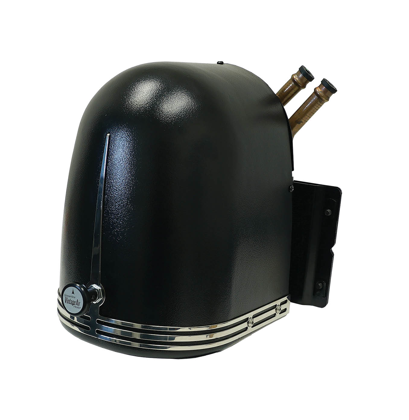
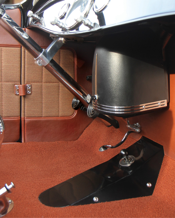
n our world of hot rods, especially early cars, the lack of a heater and/or A/C used to be the norm. Nowadays there’s a simple solution to solving heating and A/C needs. Well, it’s much easier for the closed cars, but for open roadsters (and the like) the use of A/C, while occurring more frequently, the real need is for heat. A small heater only is more affordable than an entire A/C system, and sometimes more practical. So, with this in mind, we came up with the Vintage Air (VA) Streamline Heater (PN 660066) ideally suited for open hot rods. It is designed to sit separately below the dash.

Next stop was at Hot Rods by Dean in Phoenix to check out the installation of one of the VA Streamline Heaters in (what else?) an open Model A roadster. While this is the starting point for our story, the fact is you can use this in any hot rod project where you have a front-area-only to maintain warmth.

The Streamline Heater is a powerful heating system designed with classic styling to match the Art Deco designs of the ’30s. In 1929, Ford’s Model A introduced the first of the car heaters. Based on engine heat you had to wait for the heat to be generated, which in the wintertime may be a longtime coming. The ’33 Ford was the first to use an in-dash heater with a miniature gasoline boiler. Next up in 1930, General Motors came up with the standard heater core using the car’s engine coolant and fans to heat the interior of the car. This became the industry standard. Then in 1937 Nash Motors introduced the use of climate controls, air filters, and the heater core. The first well-known passenger car/truck heater was the South Wind heater. Harry J. McCollum invented the early versions in the ’30s, offering a gas-powered heater. He sold over 3 million units by 1948.

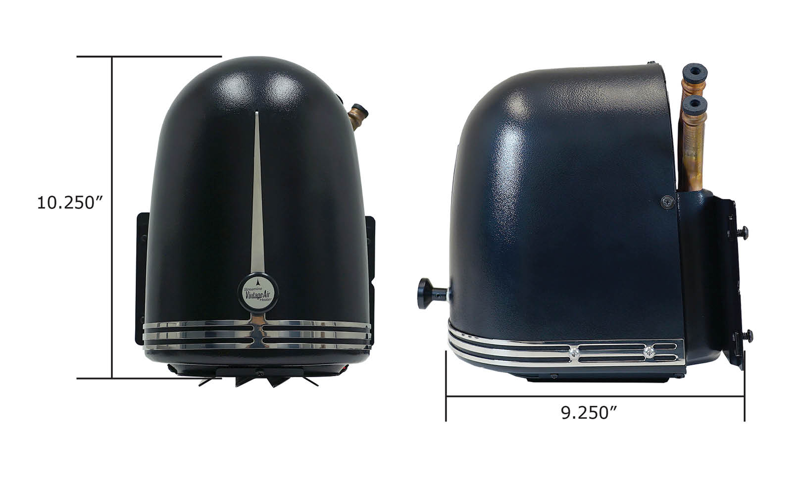
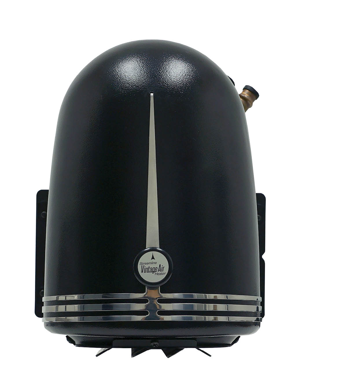
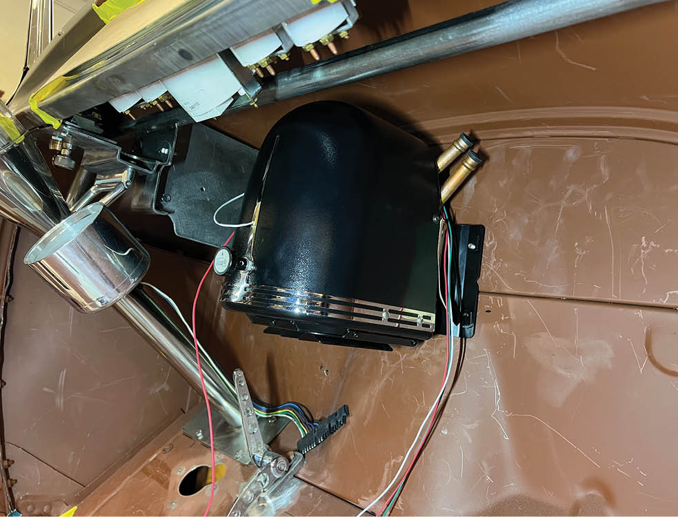
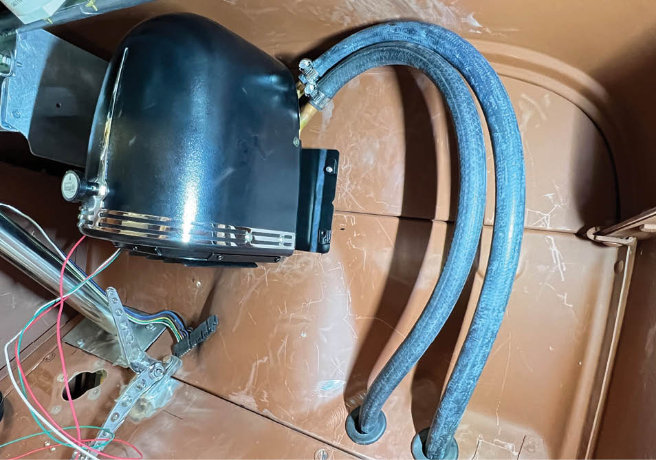
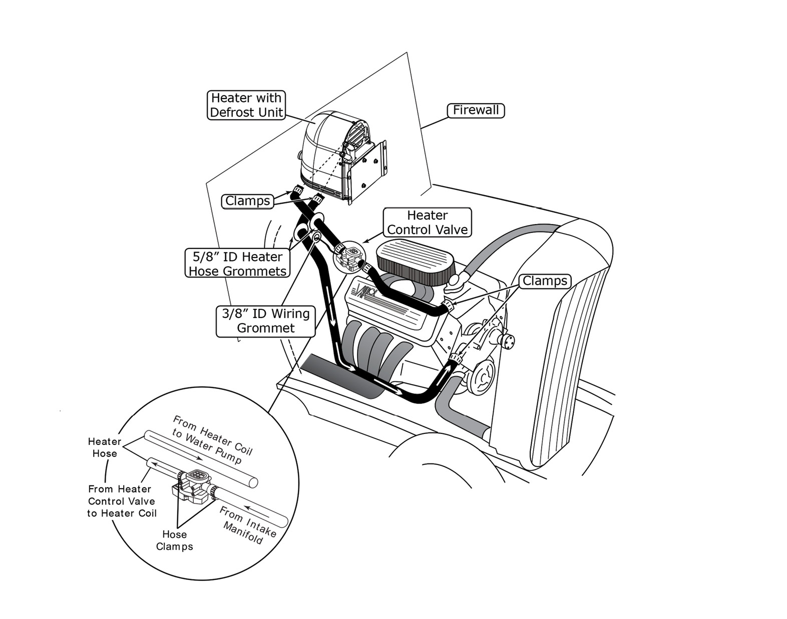
The VA Streamline Heater utilizes a molded plastic cover to portray the Art Deco–style, polished stainless steel trim, and single-knob operation for ease of use and to ensure safety. The heater louvers are used for directing air  ow out of the bottom of the unit and they are powdercoated and separate air between the driver and passenger footwell areas. There is a single control knob that regulates the three-speed blower fan and the electronically controlled heater control valve while the high efficiency copper and brass CuproBraze heater core ensures consistent, reliable heat on cold days.

Geoff Jones of Hot Rods by Dean was our go-to guy for the installation. He’s in the midst of a Model A on Deuce ’rails … the old reliable highboy roadster. While the build has plenty of cool stuff, it’s the cool air that needs a little warming up for those early morning Arizona drives. Follow along as the install is basic but the results are amazing and will add an entirely different level of comfort to driving your roadster … or any other early hot rod that could use a bit of warming up.

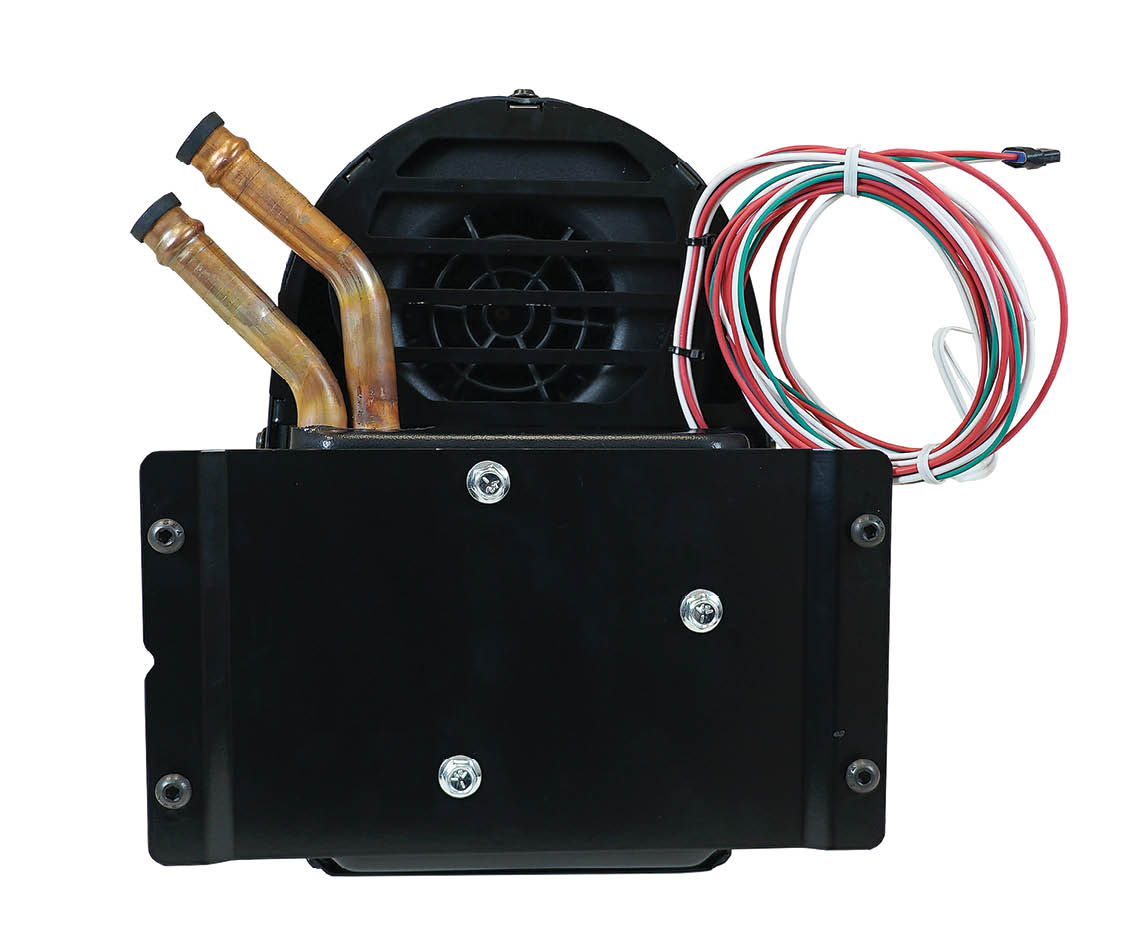
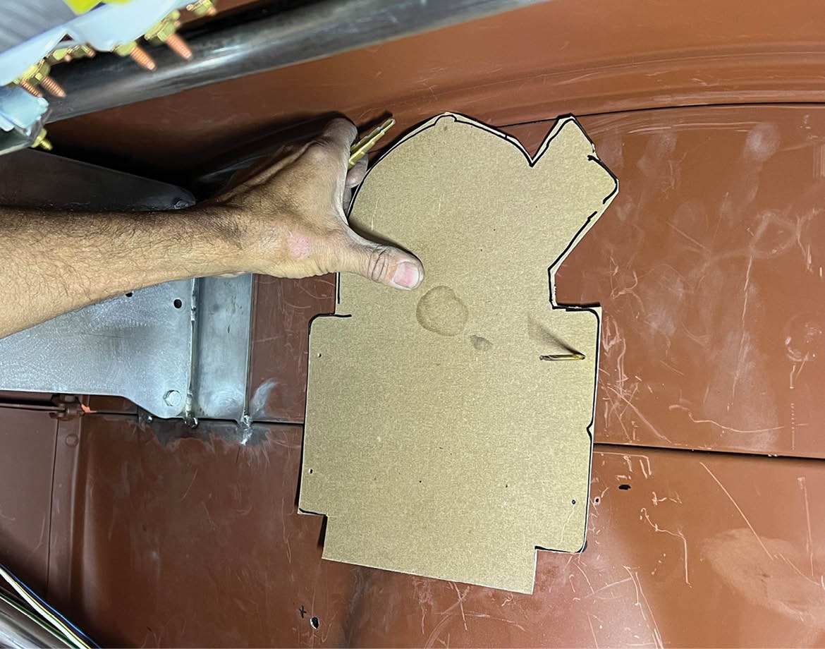
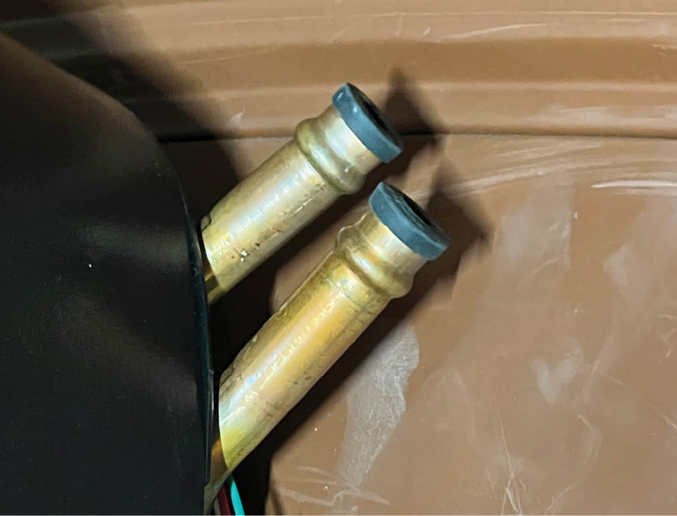
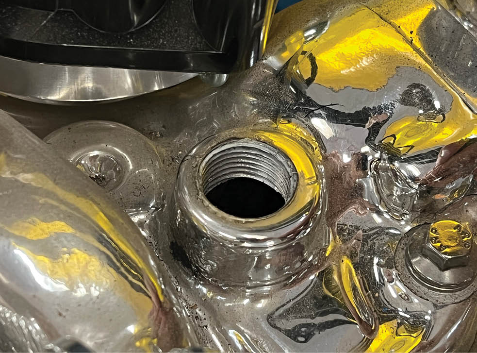
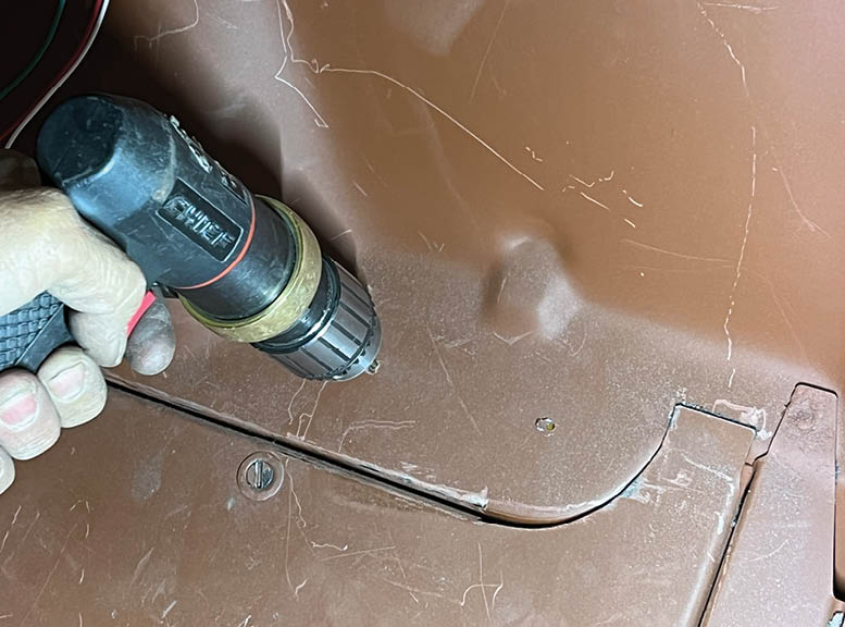
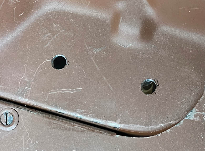
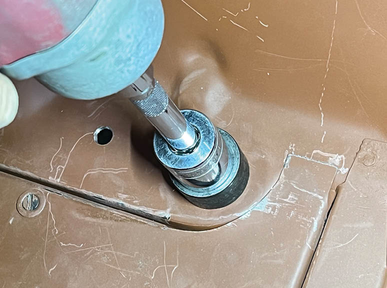
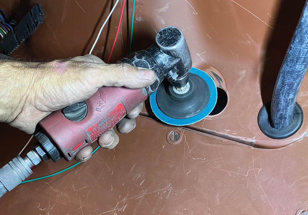
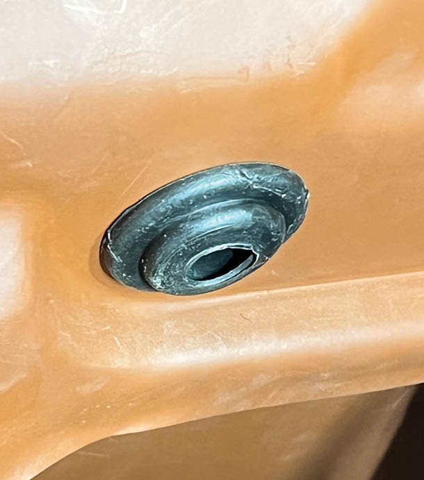
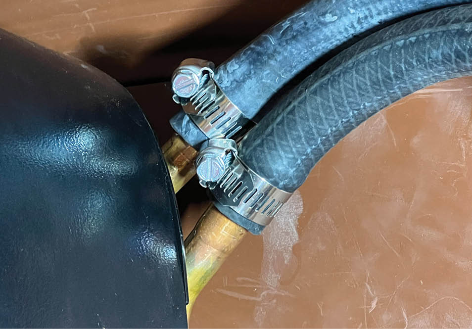
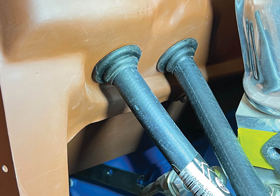
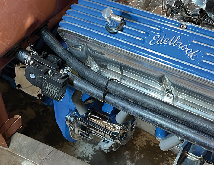
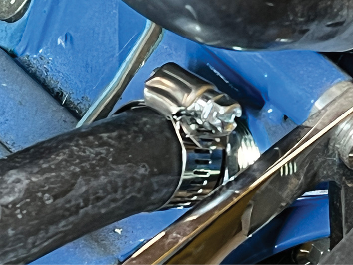
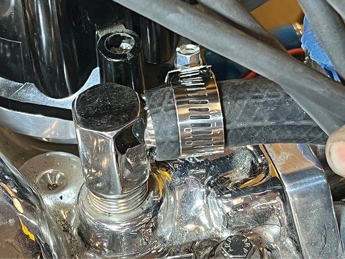
Mounting is pretty basic, requiring a few holes to be drilled and then attached to the firewall. From here there are only two fittings that run to and from the engine to deliver and return the heated water. Lastly, the electrical portion is another pretty simple project. There are two groupings of wire: One grouping comes from the heater control valve (black, yellow, red) and a second grouping that comes from the heater control (brown, white, green, red/orange).

Having been a roadster driver all of my hot rodding life, I can tell you there are a couple of other tricks that will go a long way to making your heater perform to the best of its abilities. I for one always carry a passenger blanket to throw over our legs and laps to keep the hot air in. I also have seat heaters (hey, I’m a lover of creature comforts). And the biggie, when driving along my roadster has a tonneau cover that can be placed over the passenger seat area that really helps to keep the hot air generated by the heater circulating around me. Nothing like being comfortable on a cold drive.

The Vintage Air Streamline Heater is modeled after the Art Deco–style of the ’30s. Made with a molded plastic cover it has three speeds. The standard black ABS cover can be painted to match your interior colors.
2. The Vintage Air Streamline Heater is modeled after the Art Deco–style of the ’30s. Made with a molded plastic cover it has three speeds. The standard black ABS cover can be painted to match your interior colors.
Compact in design, measuring 10.250 inches tall and 9.250 inches deep, it is ideally suited for early hot rods and any of those hard-to-get-to places where space is at a premium.
3. Compact in design, measuring 10.250 inches tall and 9.250 inches deep, it is ideally suited for early hot rods and any of those hard-to-get-to places where space is at a premium.
The mounting plate has three 1/4x1/2-inch button head screws that hold the furnished bracket to the heater. From here there are four 1/4x1/2-inch button head screws that hold the bracket to the firewall.
4. The mounting plate has three 1/4×1/2-inch button head screws that hold the furnished bracket to the heater. From here there are four 1/4×1/2-inch button head screws that hold the bracket to the firewall.
Top view of the Streamline Heater shows off the early ’30s Art Deco styling as well as the three-position switch with VA logo on top and the stainless steel trim.
5. Top view of the Streamline Heater shows off the early ’30s Art Deco styling as well as the three-position switch with VA logo on top and the stainless steel trim.
In the VA instruction manual you will find clear and concise drawings that show how the mounting bracket is affixed to the heater as well as to the firewall.
6. In the VA instruction manual you will find clear and concise drawings that show how the mounting bracket is affixed to the heater as well as to the firewall.
In our installation Jones opted to make a pattern of the rear of the heater so he knows exactly where he can fit the heater beneath the dashboard without hitting any of the dash-mounted gauges.
7. In our installation Jones opted to make a pattern of the rear of the heater so he knows exactly where he can fit the heater beneath the dashboard without hitting any of the dash-mounted gauges.
Jones used a step-drill bit to make the firewall holes for the mounting bracket.

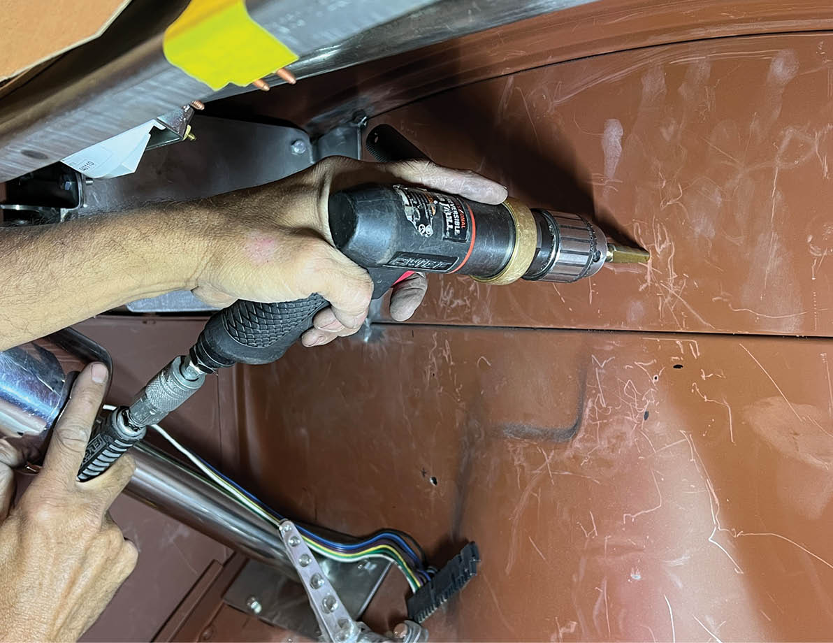
8. Jones used a step-drill bit to make the firewall holes for the mounting bracket.

Next up is the test-fit to make sure the heater doesn’t interfere with anything.
9. Next up is the test-fit to make sure the heater doesn’t interfere with anything.
The two 5/8-inch heater connections rise out of the Streamline Heater. If your engine is equipped with 3/4-inch hose, you will need to remove these and replace with two 5/8-inch heater connections as these aren’t provided.
10. The two 5/8-inch heater connections rise out of the Streamline Heater. If your engine is equipped with 3/4-inch hose, you will need to remove these and replace with two 5/8-inch heater connections as these aren’t provided.
This is the water pump fitting point on our smallblock Ford V-8. This is a low pressure suction port where the water from the heater goes back to the engine.
11. This is the water pump fitting point on our smallblock Ford V-8. This is a low pressure suction port where the water from the heater goes back to the engine.
This is the pressure side fitting point on the intake manifold near the thermostat where the water leaves the engine and heads to the heater itself.
12. This is the pressure side fitting point on the intake manifold near the thermostat where the water leaves the engine and heads to the heater itself.
In our installation two 1-1/4-inch holes were drilled in the lower portion of the firewall just above the toeboard. It is here the coming and going water hoses will be run.
two 1-1/4-inch holes were drilled in the lower portion of the firewall just above the toeboard
It is here the coming and going water hoses will be run.
13-15. In our installation two 1-1/4-inch holes were drilled in the lower portion of the firewall just above the toeboard. It is here the coming and going water hoses will be run.
Once the holes are drilled it’s a good idea to go over the raw metal edges and knock off any sharp edges before installing the grommets.
16. Once the holes are drilled it’s a good idea to go over the raw metal edges and knock off any sharp edges before installing the grommets.
A pair of propersized rubber grommets (one for each heater hose) are provided along with a smaller grommet (requires a 5/8-inch hole) for the wiring to pass between the engine and passenger compartments.
17-18. A pair of propersized rubber grommets (one for each heater hose) are provided along with a smaller grommet (requires a 5/8-inch hole) for the wiring to pass between the engine and passenger compartments.
two heater hoses clamped to the heater
two heater hoses clamped to the heater and passing through the grommet filled holes
two heater hoses clamped to the heater and passing through the grommet filled holes in the lower portion of the firewall.
19-21. Here we have our two heater hoses clamped to the heater and passing through the grommet filled holes in the lower portion of the firewall.
The heater control valve (supplied) needs to be installed in the intake heater hose (pressure side) approximately 5 inches from the firewall. Note the valve has a flow direction; make sure to get that right.
22-23. The heater control valve (supplied) needs to be installed in the intake heater hose (pressure side) approximately 5 inches from the firewall. Note the valve has a flow direction; make sure to get that right.
The heater hoses will attach to the water pump outlet as well as the intake manifold fitting outlet.
24-25. The heater hoses will attach to the water pump outlet as well as the intake manifold fitting outlet.
The smaller (single) grommet is used to pass the wires from the heater, through the firewall, and then onto the heater control valve.
26. The smaller (single) grommet is used to pass the wires from the heater, through the firewall, and then onto the heater control valve.
Here is an example of the VA Streamline Heater installed under the dash of a roadster. Provides good looks and plenty of heat to keep you warm on those cold days.
27. Here is an example of the VA Streamline Heater installed under the dash of a roadster. Provides good looks and plenty of heat to keep you warm on those cold days.
HOT RODS BY DEAN
(623) 581-1932
hotrodsbydean.com
VINTAGE AIR
(800) 862-6658
vintageair.com
Modern Rodding

VOLUME 4 • ISSUE 31 • 2023